patent · US4638200
High speed permanent magnet rotor
20 January 1987
Page 1 — bibliographic record
United States Patent (19) 11 Patent Number: 4,638,200 Le Corre et al. (45) Date of Patent: Jan. 20, 1987 (54) HIGH SPEED PERMANENT MAGNET 56) References Cited ROTOR U.S. PATENT DOCUMENTS 3,077,026 2/1963 Blackburn ........................ 29/155.53 75 Inventors: Loic Le Corre, Colombes; Albert L. 3,531,670 9/1970 Loudon ... ... 310/156 Rolland, Paris, both of France 3,956,650 5/1976 Field, II ...... ... 310/156 4,117,360 9/1978 Richter ................ ... 310/156 73 Assignee: Precision Mecanique Labinal, Bois 4,339,874 7/1982 McCarty et al... ... 310/156 d'Arcy, France 4,469,970 9/1984 Neumann ................ ... 310/26
21 Appl. No.: 822,405 FOREIGN PATENT DOCUMENTS
22 PCT Filed: May 21, 1985 195460 1 1/1983 Japan ................................... 310/156
OTHER PUBLICATIONS
S 102(e) Date: Dec. 23, 1985 "Sandwiched Magnetic Wafers", Machine Design,
87, PCT Pub. No.: WO85/05506 Primary Examiner-Patrick R. Salce Assistant Examiner-D. L. Rebsch
PCT Pub. Date: Dec. 5, 1985 Attorney, Agent, or Firm-Larson and Taylor
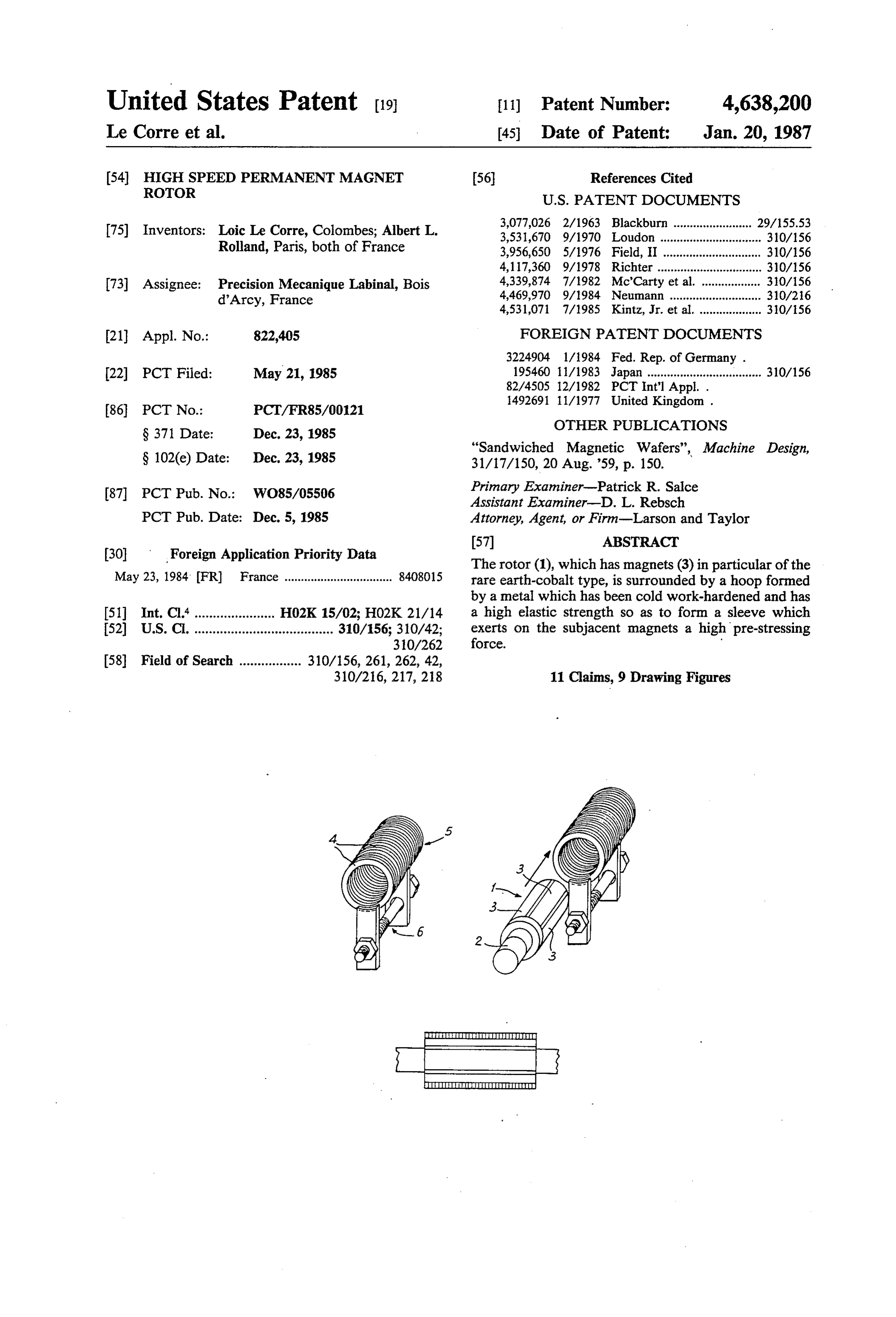
(30 Foreign Application Priority Data The rotor (1), which has magnets (3) in particular of the May 23, 1984 FR France ................................. 8408O15 rare earth-cobalt type, is surrounded by a hoop formed by a metal which has been cold work-hardened and has 51 Int. Cl....................... H02K 15/02; HO2K 21/14 a high elastic strength so as to form a sleeve which 52) U.S. C. ...................................... 310/156; 310/42; exerts on the subjacent magnets a high pre-stressing
310/216, 217, 218 11 Claims, 9 Drawing Figures
Page 2
Drawing sheet — no readable text.
Page 3
Drawing sheet — no readable text.
Page 4
those required of modern permanent magnet electric
HIGH SPEED PERMANENT MAGNET ROTOR machines.
The mounting of such a hoop formed by a sleeve in
The present invention relates to an improvement in moreover a very delicate operation.
rotating machines having magnets on the rotor and in The Japanese patent application No. 57-78,540 de particular to high-performance machines such as gener scribes a hoop formed by a winding of a very thick ators having a very high speed of rotation. ferro-magnetic metal wire and only permits a low speed The development of the technology of high-perfor of rotation if it is compared with that of the aforemen mance current generators led to the construction of tioned German patent aplication.
generators having magnets on the rotor in which the 10 U.S. Pat. No. 4,117,360 describes a very thick and rotors are made to rotate at very high speeds, as they complex hoop for a low-speed rotor. are, for example, directly driven by a turbine. U.S. Pat. No. 3,077,026 describes a rotor having a low Owing to overall size and performance, arrangements speed for ensuring a mechanical fastening of the magnets are tuted, of rotation surrounded by a complex hoop consti obsolete and there is therefore a tendency to employ 15 by spacerthe at two ends, by annular parts interconnected members carrying discontinuous strips. Such generators having magnets which are adhered or, better an arrangement allows only very low speeds of rotation still, brazed to the rotor, as described, for example, in and presents great complexity for a very thick periph Pat. No. 83 11,325 filed on July 7, 1983 in the name of eral hoop.
the applicant. However, when speeds of rotation result U.S. Pat. No. 2,735,952 describes a permanent magnet ing in tangential velocities of more than 100 meters per rotor surrounded by a very thick hoop constituted by a second, for example 200 meters per second, are ex stack of washers adapted to receive squirrel-cage bars ceeded, the safety of the fastening of the magnets is no for starting up in the manner of an induction motor. longer ensured so that such speeds cannot be reached in Such an arrangement is incapable of being used in high practice.
This is also the case of machines having magnets fixed 25 performance electric machines rotating at very high speeds of rotation.
in the conventional manner to the rotor and maintained in position by a sleeve performing the function of a The object of the present invention is to overcome hoop, the presence of which one attempts to avoid, these drawbacks backs and to provide an improvement owing to the resulting large increase in the air gap and in rotating machines having magnets on the rotor, such the behavior which at high speeds of rotation does not 30 as, for example, generators adapted to rotate at very contribute to the strength and behavior of the rotor. high speeds of rotation and permitting the maintenance The German publication DOS No. 32 24904 states of the cohesion of the rotor even at these very high speeds.
that it is known to surround magnet rotors with a non magnetic hoop composed of a material such as titanium, Another object of the invention is to provide such an which, however, does not permit attaining extremely 35 improvement which is easy to employ and effective. high speeds of rotation and moreover leads to the use of Another object of the invention is to provide such an improvement which affords a very high degree of reli thick and heavy hoops which are of little benefit from ability.
the point of view of the magnetic behavior of the assen bly. This is why this publication prescribes the con Another object of the invention is to provide such an struction of high-strength steel hoops constituted by a 40 improvement which enables the rotor to operate over a cylindrical sleeve which is pre-stressed by driving in wide range of temperatures, for example ranging from wedges. -40 to +200° C.
However, this solution presents drawbacks since the Yet another object of the invention is to provide such wedges are part of the mass and the thickness of the an improvement which is easy and cheap to carry out. hoop is locally increased. The mass of the hoop is not 45 The invention provides an improvement in rotating constant over its length and the stressing requires enor machines having magnets on the rotor adapted to rotate mous radial forces which often result in seizure. Fur at very high speeds, such as tangential velocities of 100 ther, this solution requires the insertion of supplemen m/s and more, for example 200 m/s, whose magnets are tary magnetic materials for partly saturating the inter fixed to the rotor, preferably by brazing, or optionally polar zones of the hoop so as to avoid a magnetic short 50 by other means such as adhesion, characterized in that circuit on the rotor, and this constitutes a great compli the peripheral magnets of the rotor are surrounded by a cation. thin cylindrical hoop forming a sleeve and exerting a Another solution resides in forming a hoop consti pre-stressing force on the subjacent magnets, said hoop tuted by a sleeve of synthetic resin reinforced with being made from a non-magnetic work-hardened metal carbon fibers and in pre-stressing the sleeve also by the 55 material having a high elastic limit and a small thick insertion of wedges. However, this solution excludes eSS.
any use of the device in wide temperature ranges, not The metal material is preferably a material having an only owing to the bad behavior of the hoop when there elastic strength higher than 100 daN/mm2 and prefera are large temperature variations but also owing to dif bly having a strength equal to at least 140 to 200 ferential expansion coefficients which result in a large 60 daN/mm2.
variation of the hoop pre-stressing, depending on the Preferably, the thickness of the hoop does not exceed temperatures. 7 mm and it may be advantageously on the order of 3 Various other documents describe a peripheral hoop 1.
ing of rotors provided with permanent magnets but do The thickness of the material upon work-hardening is not permit the attainment of high speeds of rotation. 65 preferably less than or equal to 1 mm. Thus, U.S. Pat. No. 3,531,670 desribes a hoop of A particularly suitable material may be a metal mate non-magnetic metal such as Inconel hot shrunk onto the rial named Phynox sold by the French firm Metal rotor. The allowed speeds of rotation are low relative to Imphy and consisting of an alloy having on the order of
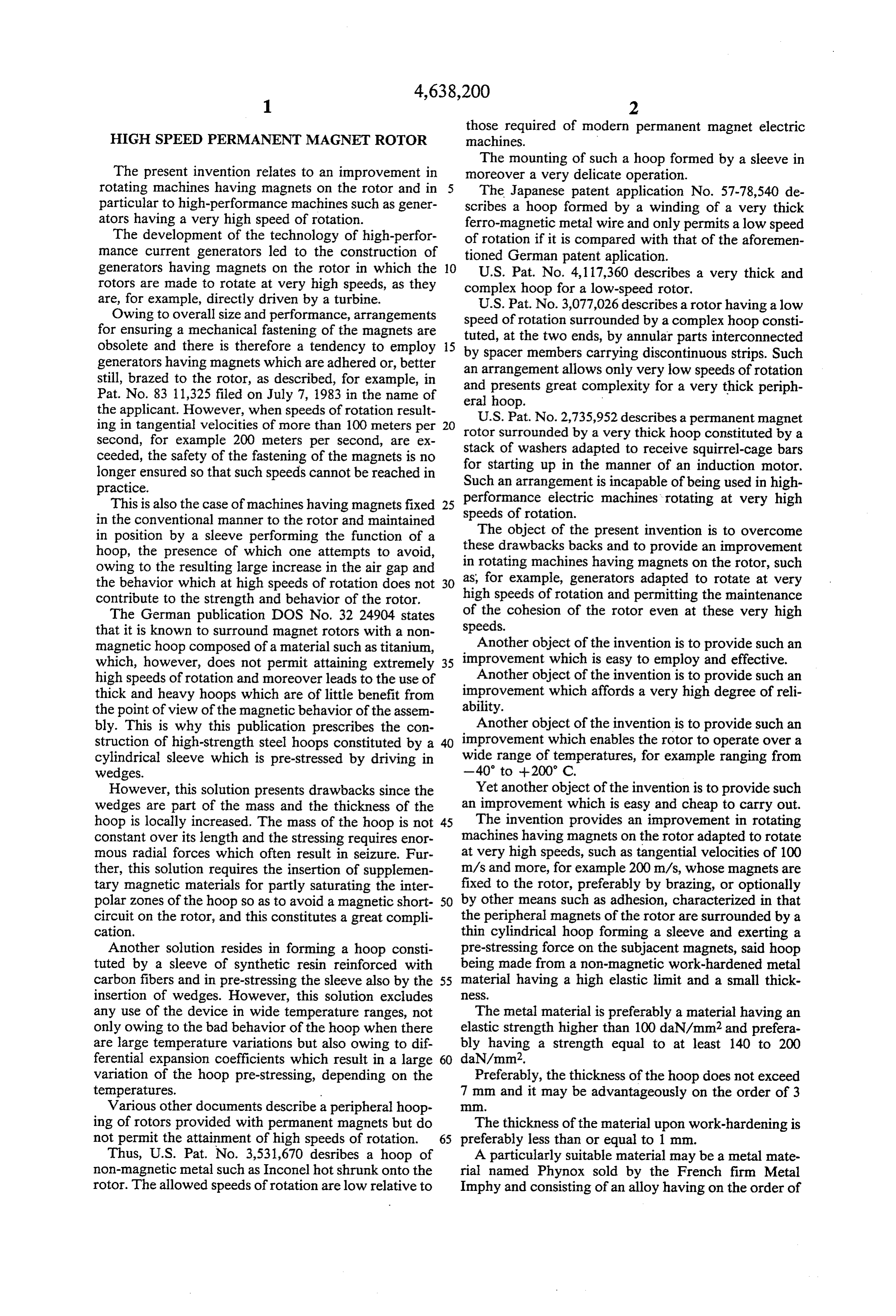
Page 5
40% Co, 20% Cr, 16% Ni, 7% Mo and also containing FIG. 6 is a view of this rotor after a winding of one iron, sold by the firm Imphy, S.A. Paris. and a half turns,
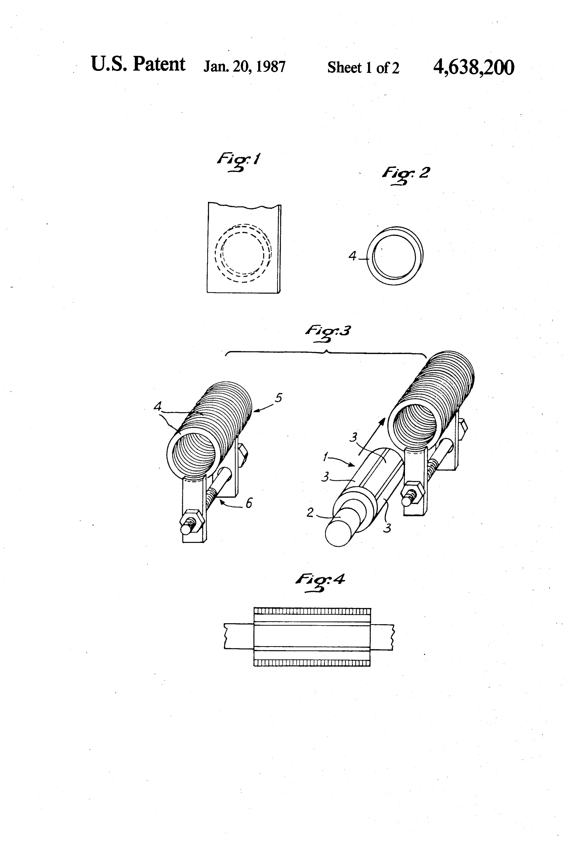
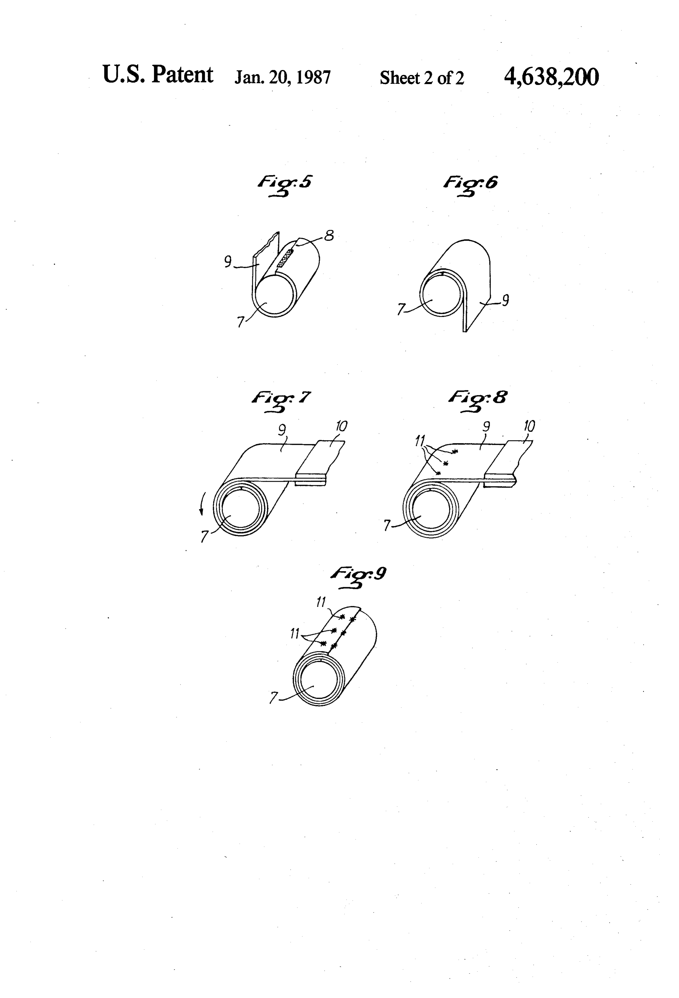
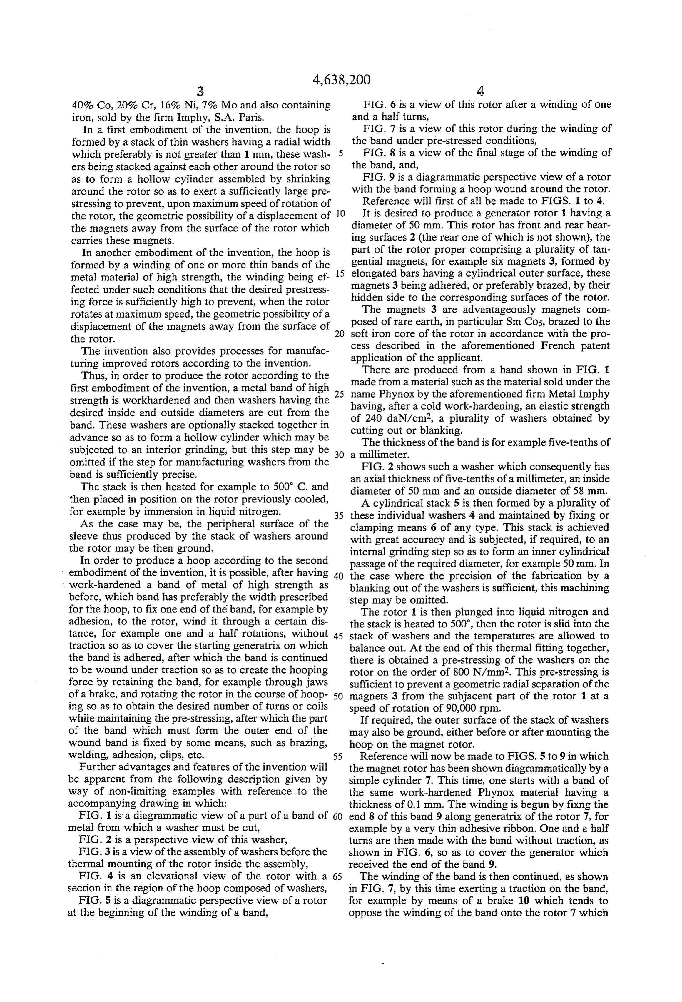
In a first embodiment of the invention, the hoop is FIG. 7 is a view of this rotor during the winding of formed by a stack of thin washers having a radial width the band under pre-stressed conditions, which preferably is not greater than 1 Inn, these wash 5 FIG. 8 is a view of the final stage of the winding of ers being stacked against each other around the rotor so the band, and, as to form a hollow cylinder assembled by shrinking FIG. 9 is a diagrammatic perspective view of a rotor around the rotor so as to exert a sufficiently large pre with the band forming a hoop wound around the rotor. stressing to prevent, upon maximum speed of rotation of Reference will first of all be made to FIGS. I to 4. the rotor, the geometric possibility of a displacement of It is desired to produce a generator rotor having a the magnets away from the surface of the rotor which diameter of 50 mm. This rotor has front and rear bear carries these magnets. ing surfaces 2 (the rear one of which is not shown), the part of the rotor proper comprising a plurality of tan
In another embodiment of the invention, the hoop is gential formed by a winding of one or more thin bands of the 15 magnets, for example six magnets 3, formed by metal material of high strength, the winding being ef elongated bars having a cylindrical outer surface, these fected under such conditions that the desired prestress magnetsside 3 being adhered, or preferably brazed, by their ing force is sufficiently high to prevent, when the rotor hidden
The to the corresponding surfaces of the rotor.
magnets 3 are advantageously magnets com rotates at maximum speed, the geometric possibility of a displacement of the magnets away from the surface of 20 posed of rare earth, in particular Sm Cos, brazed to the the rotor. soft iron core of the rotor in accordance with the pro The invention also provides processes for manufac cess described in the aforementioned French patent application of the applicant.
turing improved rotors according to the invention. There are produced from a band shown in FIG. 1 Thus, in order to produce the rotor according to the made from a material such as the material sold under the first embodiment of the invention, a metal band of high 25 name Phynox by the aforementioned firm Metal Imphy strength is workhardened and then washers having the having, after a cold work-hardening, an elastic strength desired inside and outside diameters are cut from the
band. These washers are optionally stacked together in cutting out or blanking. a plurality of washers obtained by advance so as to form a hollow cylinder which may be The thickness of the band is for example five-tenths of subjected to an interior grinding, but this step may be a millimeter.
omitted if the step for manufacturing washers from the FIG. 2 shows such a washer which consequently has band is sufficiently precise. an axial thickness offive-tenths of a millimeter, an inside The stack is then heated for example to 500 C. and diameter of 50 mm and an outside diameter of 58 mm. then placed in position on the rotor previously cooled, A cylindrical stack 5 is then formed by a plurality of for example by immersion in liquid nitrogen. 35 these individual washers 4 and maintained by fixing or As the case may be, the peripheral surface of the clamping means 6 of any type. This stack is achieved sleeve thus produced by the stack of washers around with great accuracy and is subjected, if required, to an the rotor may be then ground. internal grinding step so as to form an inner cylindrical In order to produce a hoop according to the second passage of the required diameter, for example 50mm. In embodiment of the invention, it is possible, after having the case where the precision of the fabrication by a work-hardened a band of metal of high strength as blanking out of the washers is sufficient, this machining before, which band has preferably the width prescribed step may be omitted.
for the hoop, to fix one end of the band, for example by The rotor is then plunged into liquid nitrogen and adhesion, to the rotor, wind it through a certain dis the stack is heated to 500, then the rotor is slid into the tance, for example one and a half rotations, without 45 stack of washers and the temperatures are allowed to traction so as to cover the starting generatrix on which balance out. At the end of this thermal fitting together, the band is adhered, after which the band is continued there is obtained a pre-stressing of the washers on the to be wound under traction so as to create the hooping rotor on the order of 800 N/mm2. This pre-stressing is force by retaining the band, for example through jaws sufficient to prevent a geometric radial separation of the of a brake, and rotating the rotor in the course of hoop 50 magnets 3 from the subjacent part of the rotor 1 at a ing so as to obtain the desired number of turns or coils speed of rotation of 90,000 rpm.
while maintaining the pre-stressing, after which the part If required, the outer surface of the stack of washers of the band which must form the outer end of the may also be ground, either before or after mounting the wound band is fixed by some means, such as brazing, hoop on the magnet rotor.
welding, adhesion, clips, etc. 55 Reference will now be made to FIGS. 5 to 9 in which Further advantages and features of the invention will the magnet rotor has been shown diagrammatically by a be apparent from the following description given by simple cylinder 7. This time, one starts with a band of way of non-limiting examples with reference to the the same work-hardened Phynox material having a accompanying drawing in which: thickness of 0.1 mm. The winding is begun by fixing the FIG. 1 is a diagrammatic view of a part of a band of 60 end 8 of this band 9 along generatrix of the rotor 7, for metal from which a washer must be cut, example by a very thin adhesive ribbon. One and a half FIG. 2 is a perspective view of this washer, turns are then made with the band without traction, as FIG. 3 is a view of the assembly of washers before the shown in FIG. 6, so as to cover the generator which thermal mounting of the rotor inside the assembly, received the end of the band 9. FIG. 4 is an elevational view of the rotor with a 65 The winding of the band is then continued, as shown section in the region of the hoop composed of washers, in FIG. 7, by this time exerting a traction on the band, FIG. 5 is a diagrammatic perspective view of a rotor for example by means of a brake 10 which tends to at the beginning of the winding of a band, oppose the winding of the band onto the rotor 7 which
Page 6
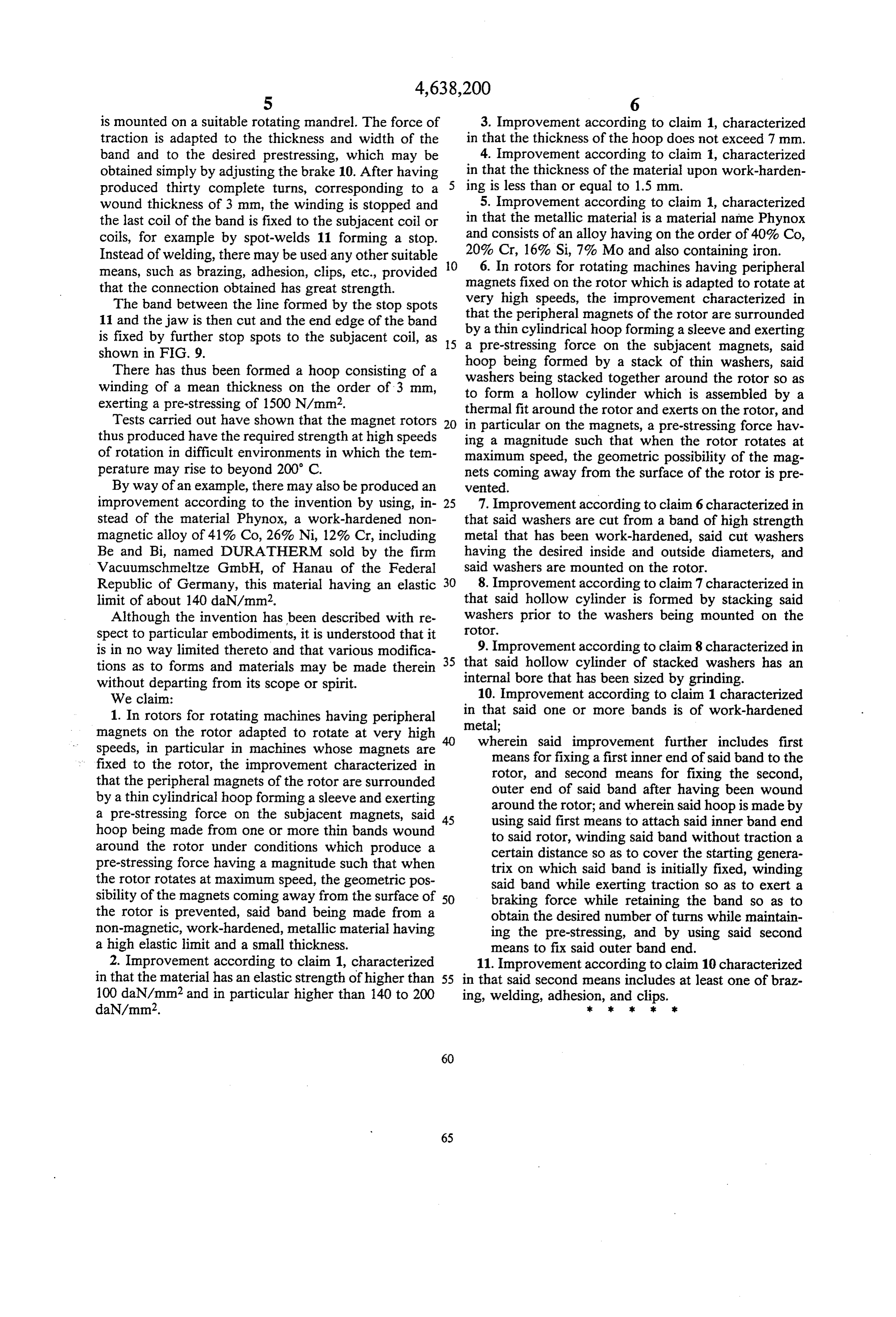
is mounted on a suitable rotating mandrel. The force of 3. Improvement according to claim 1, characterized traction is adapted to the thickness and width of the in that the thickness of the hoop does not exceed 7 mm. band and to the desired prestressing, which may be 4. Improvement according to claim 1, characterized obtained simply by adjusting the brake 10. After having in that the thickness of the material upon work-harden produced thirty complete turns, corresponding to a 5 ing is less than or equal to 1.5 mm. wound thickness of 3 mm, the winding is stopped and 5. Improvement according to claim 1, characterized the last coil of the band is fixed to the subjacent coil or in that the metallic material is a material name Phynox coils, for example by spot-welds 11 forming a stop. and consists of an alloy having on the order of 40% Co, Instead of welding, there may be used any other suitable O 20% Cr, 16% Si, 7% Mo and also containing iron. 6. In rotors for rotating machines having peripheral means, such as brazing, adhesion, clips, etc., provided that the connection obtained has great strength. magnets fixed on the rotor which is adapted to rotate at very
The band between the line formed by the stop spots that the high speeds, the improvement characterized in 11 and the jaw is then cut and the end edge of the band by peripheral magnets of the rotor are surrounded a thin cylindrical hoop forming a sleeve and exerting is fixed by further stop spots to the subjacent coil, as 5 a pre-stressing shown in FIG. 9. force on the subjacent magnets, said There has thus been formed a hoop consisting of a washers being stackedbytogether hoop being formed a stack of thin washers, said around the rotor so as winding of a mean thickness on the order of 3 mm, to form a hollow cylinder which is assembled by a exerting a pre-stressing of 1500 N/mm. thermal fit around the rotor and exerts on the rotor, and Tests carried out have shown that the magnet rotors 20 in particular on the magnets, a pre-stressing force hav thus produced have the required strength at high speeds ing a magnitude such that when the rotor rotates at of rotation in difficult environments in which the tem maximum speed, the geometric possibility of the mag perature may rise to beyond 200 C. nets coming away from the surface of the rotor is pre By way of an example, there may also be produced an vented.
improvement according to the invention by using, in 25 7. Improvement according to claim 6 characterized in stead of the material Phynox, a work-hardened non that said washers are cut from a band of high strength magnetic alloy of 41% Co, 26% Ni, 12% Cr, including metal that has been work-hardened, said cut washers Be and Bi, named DURATHERM sold by the firm having the desired inside and outside diameters, and Vacuumschneltze GmbH, of Hanau of the Federal said washers are mounted on the rotor. Republic of Germany, this material having an elastic 30 8. Improvement according to claim 7 characterized in limit of about 140 daN/mm2. that said hollow cylinder is formed by stacking said Although the invention has been described with re washersOtO.
prior to the washers being mounted on the spect to particular embodiments, it is understood that it is in no way limited thereto and that various modifica 35 9. Improvement according to claim 8 characterized in tions as to forms and materials may be made therein that said hollow cylinder of stacked washers has an without departing from its scope or spirit. internal bore that has been sized by grinding. We claim: 10. Improvement according to claim 1 characterized 1. In rotors for rotating machines having peripheral in that said one or more bands is of work-hardened magnets on the rotor adapted to rotate at very high metal;
speeds, in particular in machines whose magnets are wherein said improvement further includes first fixed to the rotor, the improvement characterized in means for fixing a first inner end of said band to the that the peripheral magnets of the rotor are surrounded rotor, and second means for fixing the second, by a thin cylindrical hoop forming a sleeve and exerting outer end of said band after having been wound a pre-stressing force on the subjacent magnets, said 45 around the rotor; and wherein said hoop is made by hoop being made from one or more thin bands wound using said first means to attach said inner band end around the rotor under conditions which produce a to said rotor, winding said band without traction a pre-stressing force having a magnitude such that when certain distance so as to cover the starting genera trix on which said band is initially fixed, winding the rotor rotates at maximum speed, the geometric pos said band while exerting traction so as to exert a sibility of the magnets coming away from the surface of 50 braking force while retaining the band so as to the rotor is prevented, said band being made from a obtain the desired number of turns while maintain non-magnetic, work-hardened, metallic material having ing the pre-stressing, and by using said second a high elastic limit and a small thickness. means to fix said outer band end. 2. Improvement according to claim 1, characterized 11. Improvement according to claim 10 characterized in that the material has an elastic strength of higher than 55 in that said second means includes at least one of braz 100 daN/mm2 and in particular higher than 140 to 200 ing, welding, adhesion, and clips.
daN/mm2. k . . . k.
Provenance
- Collection
- Cited prior art
- Original PDF
- patentimages.storage.googleapis.com →
- Filed
- 1985-05-21
- Pages
- 6
- Method
- pdftotext (the PDF's own text layer) + pdftoppm 300dpi page scans
- Source
- Google Patents bibliographic record
- Granted
- 1987-01-20
- Inventors
- Loic Le Corre; Albert L. Rolland; Precision Mecanique Labinal SA
- Transcribed from
- patentimages.storage.googleapis.com →