patent · US4700096
High speed synchronous machine having a rotor provided with magnets arranged for orthoradial magnetic induction
13 October 1987
Page 1 — bibliographic record
United States Patent (19) 11 Patent Number: 4,700,096 Epars 45) Date of Patent: Oct. 13, 1987 54) HIGH SPEED SYNCHRONOUS MACHINE 4,445,062 4/1984 Glaser ................................. 310/156 HAVING A ROTOR PROVIDED WITH 4,480,207 10/1984 Miller et al. ... 310/56 MAGNETS ARRANGED FOR FOREIGN PATENT DOCUMENTS
ORTHORADAL MAGNETIC INDUCTION
75 Inventor: Michel Epars, Montesson, France 2003568 1/1970 Fed. Rep. of Germany . 73 Assignee: Auxilec, Colombes, France 317744 1/1963 France .
(21) Appl. No.: 830,817 Primary Examiner-Donovan F. Duggan 22 Filed: Feb. 19, 1986 Attorney, Agent, or Firm-Pollock, VandeSande & 30 Foreign Application Priority Data Priddy
Feb. 28, 1985 IFR) France ................................ 85 O2966 57) ABSRACT Feb. 7, 1986 FR) France ................................ 86 01721 The synchronous machine comprises a rotor provided 51) Int. Cl. ............................................. HO2K 2/22 with permanent magnets arranged for orthoradial mag 52 U.S.C. ..................................... 310/153; 310/156 netic induction and which are disposed around the axis 58) Field of Search ................. 310/152, 153, 156, 70, in such a way that two adjacent magnets have counter 310/70 A direction inductions, pole-pieces deviating the said in 56 References Cited duction so that it becomes radial to the periphery and each of the pole-pieces being formed of half-poles sepa
2,043,010 6/1936 Reis . against the adjacent magnet, and wherein each magnet 2,907,903 10/1959 Reijnst et al. ....................... 3O/56 and each half-pole is in a single block in axial direction, 3,221, 194 1 1/965 Blackburn ........ ... 310/156 the edges of the flanges ensuring the cohesion in radial 3.41 1,059 1/968 Kaiwa .......... ... 30/156 X direction.
4,179,634 12/1979 Burson ............................ 310/156 X 4 Claims, 3 Drawing Figures
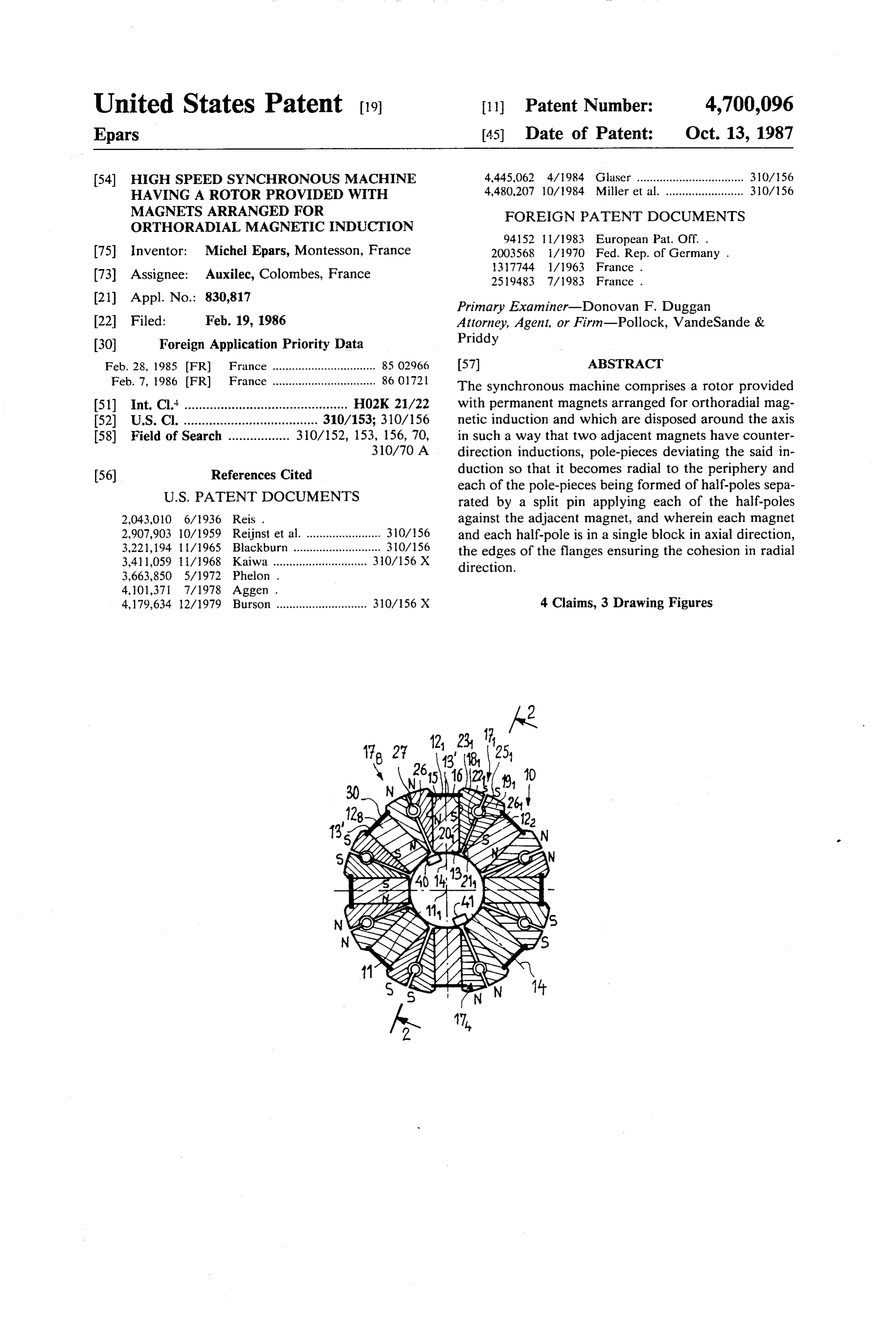
Page 2
Drawing sheet — no readable text.
Page 3
the adjacent magnet is constituted by a split pin. The
HIGH SPEED SYNCHRONOUS MACHINE rotor of the present invention is particularly simple and HAVING A ROTOR PROVIDED WITH MAGNETS cheap to produce. Furthermore since the split pin acts ARRANGED FOR ORTHORADIAL MAGNETIC as a spring, the slack is automatically adjusted, thereby ENDUCTION increasing the allowances for the manufacture of the various components of the rotor and further reducing
Field of the Invention In order to reduce the risk of lack of balance, it is preferable that all the split pins be disposed in the same
The present invention concerns a high speed syn 10 manner chronous machine, preferably a motor, comprising a side of the around the axis, for example, towards the out rotor constituted by permanent magnets the magnetic rotor.
induction of which is tangential or orthoradial and by Since the rotor has to rotate at high speed, mounting pole-pieces deviating this magnetic induction of the is achieved in the following way: the rotor is caused to permanent magnets in order for said induction to be 15 rotate at a speed higher than the maximal speed to radial at the periphery. which it will be subjected during working, then the A synchronous motor comprises a multiphase stator rotor is impregnated with a polymerizable varnish that and a rotor provided with permanent magnets. The completes the cohesion of the various components of stator is supplied with a multiphase alternating current the rotor.
that generates a rotating field causing the rotation of the 20 The present invention is, of course, in no way limited Oto. to producing a motor, but can also be utilized, for exam For the manufacture of such rotors, use is increas ple, for the manufacture of an alternator. Neither is it ingly being made of rare earth magnets, especially limited to a particular material constituting the magnets. samarium-cobalt magnets, for example, SmCo5, which In another embodiment, these magnets can be made of present a low demagnetizing rate as well as a high mag 25 ferrite.
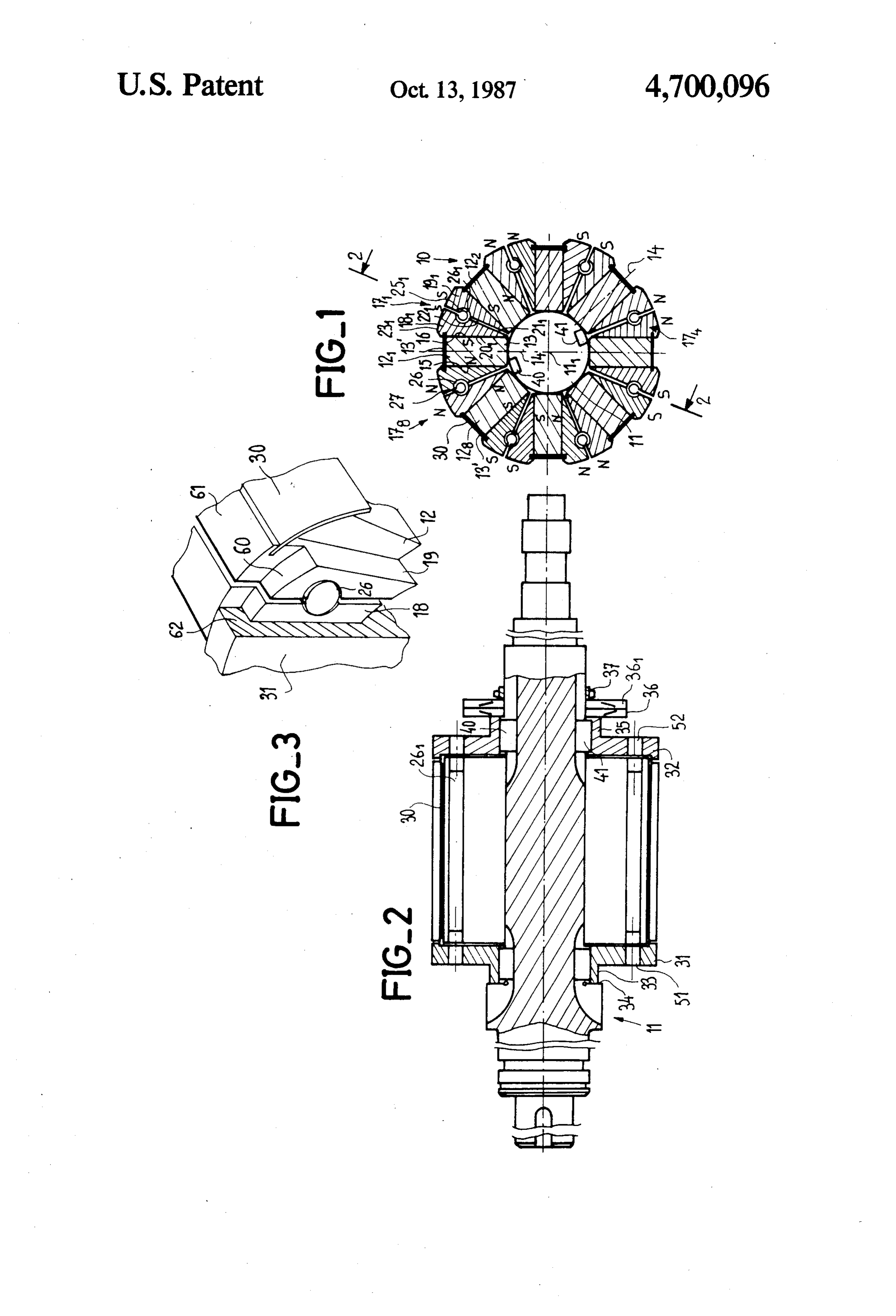
netizing energy per volume unit, thereby allowing to BRIEF DESCRIPTION OF THE DRAWINGS obtain high mass torque motors, i.e. motors with a high torque in relation to a small mass. The drawback of such Other objects, features and advantages of the inven magnets is, however, that they present a relatively low tion will become apparent from reading the following remanent induction. This is the reason why these mag 30 description of one of the embodiments, given with ref. nets are conventionally disposed in such a way that erence to the appended drawings in which: their magnetization is orthoradial and are associated to FIG. 1 is a cross-section along a plane perpendicular pole-pieces adapted to concentrate the flux, thereby to the axis of a rotor according to the invention; allowing to confer upon the induction the radial direc FIG. 2 is a section along the line 2,2 of FIG. 1; and tion in the air-gap. In this way, the two poles of each 35 FIG. 3 is a perspective view on a larger scale of a part magnet are fully utilized.
This heterogeneous structure of the rotor raises me of the end of the rotor represented in FIG. 1. chanical cohesion problems that are more difficult to DETAILED DESCRIPTION OF THE overcome as the speed of rotation increases. In order to DRAWINGS improve this cohesion at very high speeds, of about 50 In the example, the motor is of the autosynchronous 000 rpm, French patent published under No. 2519 483 type, sometimes known proposes a laminated rotor formed of a staggered stack, motor, with a multiphase asstator a brushless direct current (not represented) each in the axial direction, of nonmagnetic disks for maintain winding of which is in series with a semi-conductor ing the magnets and which are crossed through by these switch controlled by an electronic circuit in order that magnets and magnetic plates in contact with the mag the torque be constant.
nets, this stack being maintained in radial direction by 45 bars crossing through the plates and the disks. Further theThe rotor 10 comprises, uniformly distributed around shaft 11, which is preferably made of a nonmagnetic more, in the rotor described in the above-mentioned
French patent, each pole-piece between two adjacent material, eight magnets 121, 122, ... 128 made of samari magnets comprises two portions, the separation line um-cobalt, each having the form of a rectangular paral running in the radial direction, and prestressed means 50 lelepiped extending parallel to the axis and which, in are disposed between the two half pole-pieces so as to section, small sides 13 and 13' of tangential direction. Furthermore, the magnetization of each of these mag urge each of them against the corresponding magnet.
This rotor, which is particularly well adapted to high nets 12 is orthoradial, i.e. also in tangential direction, speeds, has, however, a complicated form and is expen parallel to the small side 13 and thus perpendicular to a sive to produce. 55 corresponding radius 14. Therefore, the magnet 121 has a face 15, perpendicular to the tangential face 13, consti
SUMMARY OF THE INVENTION tuting the north pole (N) and a face 16, which is parallel The present invention aims at obtaining a rotor in thereto, constituting the south pole (S). tended to rotate at high speeds, of about 15 000 rpm, The magnets are disposed in such a manner that the which is of a simpler design and less expensive than that closest faces of two adjacent magnets have the same disclosed in the above-mentioned French patent. polarity. Thus each pole-piece disposed between two It is characterized in that each magnet and each pole neighboring magnets presents a sole polarity. For exam piece is of a single block in the axial direction, and in ple, the pole-piece 171 between the magnets 121 and 122 that the cohesion in the radial direction is ensured by constitutes a south pole.
the edges of the two end flanges being applied against 65 Each pole-piece 17 is formed of two parts 18 and 19, shoulders located at the ends of the pole-pieces. Fur made, for example, of mild steel and having an axial thermore, the means disposed between the two half length slightly greater than that of the elements 12, as is pole-pieces for pressing each of them against one face of seen in FIG. 3. The separation face between the two
Page 4
half poles 18, 19 is along a radial plane. Each half pole, corresponding flange 31 in order to ensure the radial 18 or 19, has in section through a plane perpendicular to securement of the rotor.
the axis 111, substantially the form of a rectangular Therefore, in operation, when the rotor rotates at triangle. Thus, the half-pole 18, has a face 20 applied high speed, the centrifugal force applies the magnets 12 against the face 16 of the magnet 121, a face 211 opposite against the plates 30 integral with the half pole-pieces the corresponding face 221 of the half-pole 191 and an 18, 19 that are maintained together in the radial direc external face 231 in the form of a zone of a cylinder tion due to the edges 62 of the flanges 31 and 32. constituting the external surface of the rotor. The split pins 26 constitute simple means for ensuring Each of the faces 21 and 221 includes a groove in the lowscohesion the of the rotor and which, furthermore, al the adjustment of the slack. The marking of the form of a semi-cylinder having an axis parallel to the 10 angular position of the rotor due to the pins is particu axis 111 and they have the same radius. These grooves larly useful for an autosynchronous motor whose stator form a cylindrical recess 251 within which is disposed a is supplied as a function of the angular position of the split pin 26 formed of a split tube according to a gener OtOt.
ating line. The dimensions of the recess and of the split 15 As already mentioned herein-above, the opening of pin are such that the split pin is stress mounted so as to the splits in the same direction allows to limit the risks urge the half-pole 181 against the magnet 12 and the of lack of balance; furthermore, the opening towards half-pole 191 against the magnet 122. After the final the outside facilitates the control of the positions as mounting operation, the faces 211 and 221 of the two from the periphery, and in particular from the split half-poles 18 and 191 are separated by a space of about 20 between the faces 21 and 22 of the two adjacent half 1 mm. pole-pieces.
In the preferred embodiment the split 27 of each pin Since the rotor has to rotate at high speed, the mount is turned outwardly with respect to the stator to coin ing operation is completed in the following manner: the cide with the space between half-poles. rotor is driven at very high speed, higher than the maxi It is preferable that each pin be made of a nonmag mal operating speed; then the rotor is subjected to a netic material in order to reduce the transversal mag grease removing treatment and, finally, it is impreg netic leaks due to the armature reaction. nated with a polymerizable varnish that thereafter heat Each half-pole 18, 19 extends in the radial direction ous hardened in order to complete the cohesion of the vari beyond the external face 13 of each magnet 12. In the 30 I claim: elements of the rotor.
portion extending beyond the face 20, a groove of radial direction is provided for receiving a nonmagnetic 1ng:1. A high speed synchronous machine rotor compris wedging plate 30 applied against the face 13' of the a plurality of magnets equally spaced circumferen magnet 12. Thus, the longitudinal edges, parallel to axis tially and angularly alternating with a plurality of 111, of the plate 30 are housed within the grooves of the 35 poles, each pole including two half-pole pieces, half-poles at each side of the corresponding magnet 12. adjacent radial faces of said half-pole pieces being In the axial direction, the magnets and the pole-pieces spaced apart;
are maintained together by end flanges 31 and 32 means for restraining displacement of said poles and (FIGS. 2 and 3) which includes holes 51, 52 free for magnets in an axial direction; providing passage for the pins in order to facilitate their 40 first means for restraining radial displacement of said mounting, on the one hand, and to allow the angular poles and magnets, said first means including a split marking of the rotor, on the other hand. pin disposed in a recess formed in said adjacent The flange 31 is extended, opposite the assembly of faces of said half-pole pieces of each pole, said pin the magnets and the pole-pieces 17, by a nose 33 resting having a split positioned radially within the recess, upon a shoulder 34 of the shaft 11. The flange 32 is also 45 said pin forcing angularly outward opposite faces extended by a nose 35, opposite the assembly of magnets of said half-pole pieces against said magnets and pole-pieces, against which abuts a flexible washer thereby providing cohesion between the magnets 36 urged by another washer 361 and a nut 37 cooperat and pole pieces of said rotor; and ing with a threaded part of the shaft. The washers 36 second radial restraining means including axially and 361 allow to limit the axial stress upon the various 50 spaced flange members having continuous edges elements of the rotor in order to prevent any deforma coacting with corresponding outwardly extending tion of the shaft and to limit the machining precision shoulders formed on said half pole-piece. required in the production of the elements. 2. A rotor according to claim 1, further comprising The flanges 31 and 32 are blocked in rotation upon third radial againstrestraining means including a plate member the shaft by the wedges 40 and 41 diametrically oppo 55 positioned nets and grooves radially outward faces of said mag formed in said opposite faces of said site at the level of the north pole-pieces, respectively half-pole pieces adjacent to said magnet for receiving 178 and 174. opposite edges of said plate member. At the outer end each pole-piece 18, 19 extends in the 3. A rotor according to claim 2 wherein said plate axial direction beyond the magnet 12. Furthermore, at 60 member is made of nonmagnetic material. the outer ends, these pole-pieces are provided with a 4. A high speed synchronous machine according to shoulder 60 forming a cylindrical surface having a di claim 3, wherein said recess is formed from mating ameter smaller than the diameter of the external surface semi-cylindrical grooves located in each said adjacent 61 at the pole-pieces and closer to axis 111 than the plate face.
30. These shoulders 60 cooperate with an edge 62 of the 65 k k k k x
Provenance
- Collection
- Cited prior art
- Original PDF
- patentimages.storage.googleapis.com →
- Filed
- 1986-02-19
- Pages
- 4
- Method
- pdftotext (the PDF's own text layer) + pdftoppm 300dpi page scans
- Source
- Google Patents bibliographic record
- Granted
- 1987-10-13
- Inventors
- Michel Epars; Auxilec SA
- Transcribed from
- patentimages.storage.googleapis.com →