patent · US4976587
Composite wind turbine rotor blade and method for making same
11 December 1990
Page 1 — bibliographic record
United States Patent (19) 11 Patent Number: 4,976,587 Johnston et al. 45 Date of Patent: Dec. 11, 1990 54 COMPOSITE WIND TURBINE ROTOR 3,586,460 6/1971 Toner ............................. 416/230 A BLADE AND METHOD FOR MAKING SAME 3,967,996 7/1976 Kamov et al. .. ... 416/229 R 4,260,332 4/1981 Weingart et al. ... 416/230 75) Inventors: J. Ford Johnston, Sunland; William 4,295,790' 10/1981 Eggert, Jr. .......................... 416/226 A. Farone, Irvine; Amir Mikhail, 4,392,781 7/1983 Mouille et al. .. ... 416/DIG. 2 Northridge, all of Calif. 4411,598 10/1983 Okada .......... ... 416/DIG. 2 o 4,668,169 5/1987 Perry .... ... 416/223 R (73) Assignee: DWR Wind Technologies Inc., San 4,728,263 3/1988 Basso .... ... 416/226 Francisco, Calif. 4,806,077 2/1989 Bost................................. 416/229 R (21) Appl. No.: 221,897 Primary Examiner-Robert E. Garrett (22 Filed: Jul. 20, 1988 Assistant Examiner-John T. Kwon Attorney, Agent, or Firm-Gottlieb, Rackman & 51) Int. Cl................. do o be es u de Po a or se F01D 5/14 Reisman
52 U.S. C. .................................... 416/230; 416/226;
58 Field of Search ................... 9/2222228. A wind turbine rotor blade including NASA LS (1) - 416/229 R, 229 A, 230,; : Big s 04xx airfoil sections having a twist not greater than 8 /258; /157, and a construction for such a blade which includes no 56 References Cited parting line along the leading edge. The bond between
channels of "C" shaped cross section affixed to the skin 2,465,007 3/1949 Bragdon et al. .................... 416/229 and the spar. A method for manufacturing a rotor blade 2,754,915 7/1956 Echeverria, Jr. .. ... 416/226 of this construction.
3,028,292 4/1962 Hinds .............. 416/226 3,349,157 10/1967 Parsons ... . 416/230. A 3,390,393 6/1968 Upton .................................. 46/226 49 Claims, 12 Drawing Sheets
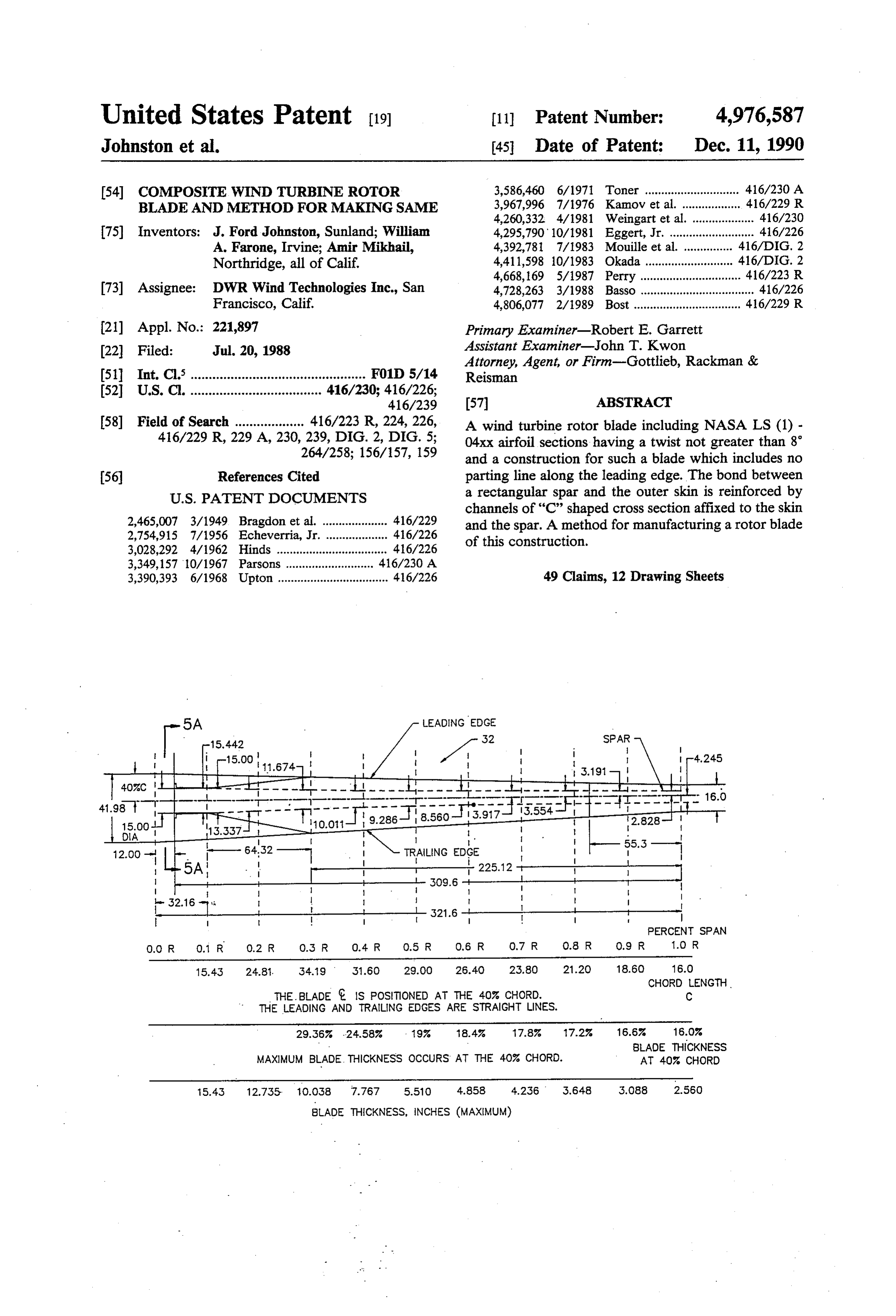
LEADING EDGE
PERCENT SPAN
O.OR 0.1 R 0.2 R O.3 R O.4 R 0.5 R 0.6 R 0.7 R 0.8 R 0.9 R 1.0 R
CHORD LENGTH
THE BLADE Is POSITIONED AT THE 40% CHORD. C
THE LEADING AND TRALING EDGES ARE STRAIGHT LINES.
29.36% .24.58% . 19% 18.4% 17.8% 17.2% 18.8% 18.0%
BLADE THICKNESS
MAXIMUM BLADE THICKNESS OCCURS AT THE 40% CHORD. AT 40% CHORD
BLADE THICKNESS, INCHES (MAXIMUM)
Page 2
Drawing sheet — no readable text.
Page 3
Drawing sheet — no readable text.
Page 4
Drawing sheet — no readable text.
Page 5
Drawing sheet — no readable text.
Page 6
Drawing sheet — no readable text.
Page 7
Drawing sheet — no readable text.
Page 8
Drawing sheet — no readable text.
Page 9
Drawing sheet — no readable text.
Page 10
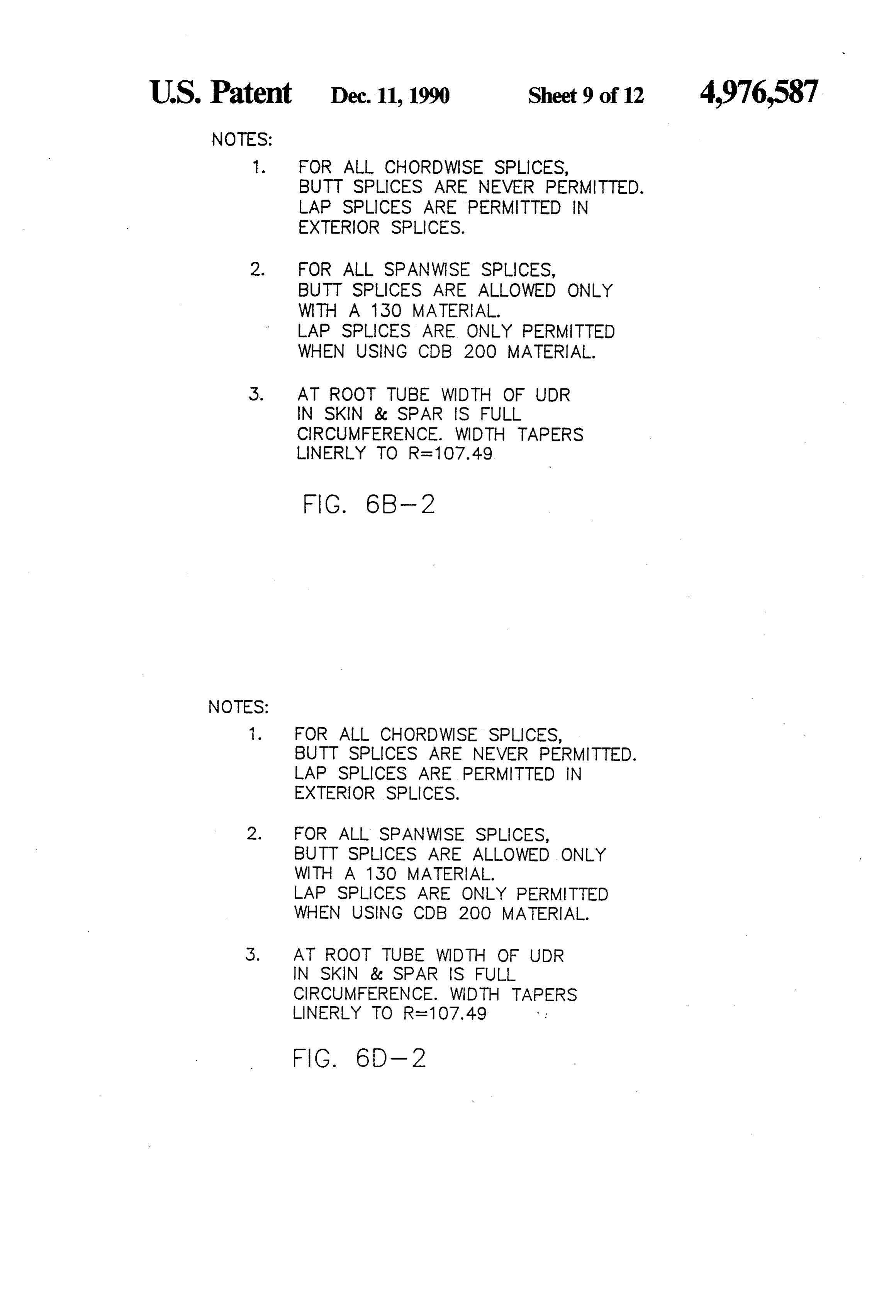
NOTES:
1. FOR ALL CHORDWISE SPLICES,
BUTT SPLCES ARE NEVER PERMITTED.
LAP SPLCES ARE PERMITTED IN
EXTERIOR SPLCES.
FOR ALL SPAN WISE SPLCES,
BUTT SPLCES ARE ALLOWED ONLY
WITH A 130 MATERAL.
LAP SPLCES ARE ONLY PERMITTED
WHEN USING CDB 200 MATERAL.
AT ROOT TUBE WIDTH OF UDR
N SKN & SPAR S FULL
CIRCUMFERENCE. WDTH TAPERS
LNERLY TO R=1 O7.49
NOTES:
FOR ALL CHORDWISE SPLICES,
BUTT SPLICES ARE NEVER PERMITTED
LAP SPLICES ARE PERMITTED IN
EXTERIOR SPLCES.
FOR ALL SPAN WISE SPLICES,
BUTT SPLCES ARE ALLOWED ONLY
WITH A 13O MAERA.
LAP SPLCES ARE ONLY PERMITTED
WHEN USING CDB 200 MATERAL.
AT ROOT TUBE WIDTH OF UDR
N SKN & SPAR S FULL
CIRCUMFERENCE. WDTH TAPERS
Page 11
Drawing sheet — no readable text.
Page 12
Drawing sheet — no readable text.
Page 13
Drawing sheet — no readable text.
Page 14
blowing, it has been found in practice that the rate of
COMPOSITE WIND TURBINE ROTOR BLADE yaw rotation is slow compared to the rapid and variable AND METHOD FOR MAKING SAME changes in wind direction which are common in nature. These additional loads are causing major damage in
TECHNICAL FIELD turbine systems in areas such as California. This invention relates generally to wind turbine rotor A factor contributing to mechanical failure of exist blades. More particularly, this invention relates to wind ing wind turbine blades is that the aerodynamic loads, turbine rotor blades manufactured from composite ma which begin at the tip, are integrated along the length of terials, and to a method for manufacturing such rotor O the blade. Therefore, longer blades (especially those blades. producing more energy due to increased airfoil effi BACKGROUND ART ciency) will have higher loads at the base or root, thus making the design of the structure more critical.
In recent years, it has become apparent that conven Another major problem associated with existing tional methods of generating electricity will soon be 15 wind turbine blades is leading and trailing edge crack insufficient to meet the world's ever-growing need for ing. In prior designs the top half of the blade is formed electric power. Several factors, including the pollution in one mold, while the bottom half is formed in another which results from the combustion of fossil fuels, the mold.
dangers associated with the operation of nuclear reac tively, Then, both halfs are sealed to a spar. Alterna the skin is “hinged' either fore or aft. Defects in tors, and the limitations inherent in the traditional hy the leading edge can ruin airfoil efficiency. Such defects droelectric as well as in the more modern solar energy are more likely to occur along a joint between sepa approaches to the generation of electricity, have en couraged the development of alternative sources of rately molded parts, and may occur either during manu electric power, such as the wind turbine generator. facture or during continued use. It is often necessary to Wind turbines convert wind energy to electrical en rework or make "repairs' to newly manufactured parts, ergy in a manner analogous to the way in which the 25 or to replace blades in the field due to premature fail windmills of Western Europe converted wind energy to ures.
mechanical energy for pumping water or operating One prior approach to increasing energy output is grinding mills. A wind turbine generally includes a simply to increase the swept area through the use of rotor which is mounted for rotation near the apex of a devices called "hub extenders.' These devices fit be tower approximately 18 to 50 meters in height. The tween the base of the existing blades and the hub, thus rotor acts as the prime mover for an electrical generator increasing the length of the blades and therefore the which provides power through transformers and sub station controlled connections, to the local utility swept area. However, these devices increase the total weight of the rotor system, increase aerodynamic and power grid.
Generally, wind energy projects include the installa 35 gravity loads on the mechanical components of the wind turbine and also require a double set of attachment tion of large numbers of wind turbine generating sys bolts, tems at locations having favorable wind conditions. ponentthus introducing another point of potential com failure.
Several of these so-called "wind farms' are located in the state of California. The Vestas V-15 and Vestas V-17 wind turbine gen In late 1986 it became apparent that the various wind erators are found at various wind farm sites in Califor energy projects using wind turbines to generate electri nia. These machines are typical of the Danish turbines cal energy suffered from a major problem in that the used in many wind energy projects Both of these ma turbines were not receiving the amount of wind energy chines are three blade, upwind, active yaw (turning into that was projected based on the initial wind studies that the wind) machines running nearly synchronously at were conducted. There have been many reasons ad 45 approximately 51 rpm. The V-15 has a 75kw electric vanced for this shortfall of wind energy. Little can be induction generator (nameplate 65kw) and the V-17 has done about the wind itself, with the exception of under a 110kw generator (nameplate 90kw). The V15 uses standing the available resource better (by using direct 7.5M blades of a basic NACA 44xx airfoil series and the measurement and analysis). However, new rotor blades, V-17 uses 8.5M blades of the same series. The average designed to take better advantage of the available wind 50 thickness-to-chord ratio for the series used is approxi resource, provide an opportunity for energy increase. mately 0.18 and thus the typical airfoil cross section is Another major problem which has been associated an NACA4418. The existing blades are highly twisted, with wind energy projects is mechanical failure in exist with the twist changing by about 18 from root to tip. In ing wind turbines. It has been found that the direction of use, these NACA 4418 blades are also subject to consid the wind is not always along the rotational axis of the 55 erable fouling by dirt and insect debris which reduce rotor. Off-axis wind components cause mechanical loads on the blades that were not adequately considered operating cessity.
efficiency and make frequent washing a ne
The blades also weigh on the order of when the original blades were designed. Particularly, 1,000-1,200 pounds each, which is considered excessive when the wind rises along a slope to a wind turbine placed at the top of the slope, it creates an additional 60 for their function by modern technology standards. "yawing' (side to side) load. This is sometimes called These blades, or very similar designs, are used in thou “vertical flow.” When the wind comes in from either sands of turbines installed in California. side ("yawed flow") it creates an additional "pitching' DISCLOSURE OF THE INVENTION load (bottom to top or top to bottom, depending on the yawed flow direction). Although the wind turbines 65 It is the principal object of the present invention to have "active yaw systems' which are designed to rotate provide a wind turbine rotor blade which may be used in response to changes in wind direction so that the to generate increased power at relatively low wind rotor always faces the direction from which the wind is speeds.
Page 15
It is another object of the invention to provide a wind Further, in accordance with the invention a wind turbine blade which reduces turbine loads, particularly turbine rotor blade includes a leading edge assembly with regard to off-axis winds. formed of layers of fiberglass impregnated with a poly It is still another object of the invention to provide a mer resin. The leading edge assembly has a closed lead wind turbine blade with increased structural integrity ing edge and rear edges defining an open rear. Several and which has a reduced chance of catastrophic failure of the layers extend short of the rear edges so that the over a lifetime measured in decades. thickness of the skin is reduced in first attachment re It is an additional object of the invention to provide a gions adjacent the rear edges. The rotor blade also wind turbine blade that is not subject to the develop includes a trailing edge assembly, also formed of layers ment of leading edge defects which decrease airfoil O of fiberglass, impregnated with a polymer resin. The efficiency. trailing edge assembly has a closed trailing edge and It is yet a further object of the invention to provide a front edges defining an open front. Several of the layers wind turbine blade which maintains its efficiency when extend short of the front edges so that the thickness of dirt and insect debris are deposited on the blade. the skin is reduced in second attachment regions adja It is still another object of the invention to provide a 15 cent the front edges. The first attachment regions and wind turbine blade and a method of manufacturing the the second attachment regions are of complementary same which is low in cost. shape. The first attachment regions are of a thickness In accordance with the invention, a wind turbine sufficient to receive the reduced thickness of skin in the rotor blade is formed with LSC1) - 04xx airfoil sections. second attachment regions.
The turbine blade has a thickness-to-chord ratio of sub 20 In accordance with the preferred embodiment, the stantially sixteen percent at full radius This ratio in inner layers of the leading edge assembly extend short creases to substantially nineteen percent at one half full of the rear edges, while the outer layers of the trailing radius and substantially twenty-nine percent at three edge assembly extend short of the front edges. The first tenths full radius. Preferably, the thickness-to-chord wall of the spar is affixed to the inner surfaces of both ratio at three tenths full radius is 29.4%, and the blade 25 the leading edge assembly and the trailing edge assem thickness is maximum at a 40% chord. The rotor has a . bly so as to span upper attachment regions and lower twist equal to zero from full radius to 50% full radius, attachment regions. Preferably, polymer foam stiffening but the twist then increases to a value of not more than inserts extending longitudinally in the trailing edge 8 degrees at the theoretical hub of the rotor blade. Pref. assembly increase stiffness so that the blade maintains erably, the chord length increases linearly from full 30 camber under load. The stiffening inserts are inserted radius to three tenths full radius. The chord length then between two of the layers of the trailing edge assembly, decreases from three tenths full radius toward the hub. i.e., the layers are separated to define a channel for The leading edge and the trailing edge of the blade are receiving each stiffening insert. Preferably, one insert is preferably both substantially linear. The shape of the disposed in a first wall of the trailing edge assembly and blade changes from an airfoil section to a circular tube 35 a second insert is disposed in a second wall of the trail extending longitudinally of the blade inward from three ing edge assembly.
tenths of full radius. A tubular section is used to connect In accordance with the method of the invention a the blade to the rotor hub. composite blade for a wind turbine is constructed by Also in accordance with the invention, a wind turbine inserting first plies of fibrous material impregnated with rotor blade has an outer skin of fiberglass mat impreg 40 a polymer resin into a first mold. The first mold is nated with a polymer resin. The rotor blade encloses a shaped to define the trailing edge assembly of the blade. spar extending longitudinally in the rotor blade. The Second plies of a fibrous material impregnated with a spar has a substantially rectangular cross-section having polymer resin are then wrapped around a mandrel. The a first side in contact with a first inner surface of the skin mandrel is sized and shaped to define a spar member to and a second side in contact with a second inner surface 45 extend longitudinally within the blade. Third plies of of the skin. A third side and a fourth side of the rectan the fibrous material impregnated with the polymer resin gular spar extend substantially perpendicularly to the are then inserted into a second mold. The second mold inner surfaces of the skin and connect the first and sec is sized and shaped to define the leading edge assembly ond sides of the spar. of the blade. The first mold, the second mold and the The rotor blade also encloses two longitudinally ex 50 mandrel are then aligned so that the mandrel wrapped tending channels adjacent the spar. A first channel has with the second plies to define the spar member is dis a first wall extending parallel to the third side of the posed internally between the leading edge assembly and spar and affixed thereto, a second wall extending paral the trailing edge assembly, and so that the leading edge lel to the first inner surface of the skin and affixed assembly and the trailing edge assembly are aligned to thereto, and a third wall extending parallel to the sec 55 define the blade. The polymer resin is then cured. ond inner surface of the skin and affixed thereto. A Preferably, the mandrel is positioned so that plies on second channel has a first wall extending parallel to the the external surface of the mandrel are in contact with fourth side of the spar and is affixed thereto. A second plies on the internal surfaces of both the leading edge wall of the second channel extends parallel to the first assembly and the trailing edge assembly. inner surface of the skin and is affixed thereto. A third 60 The method further comprises the step of sizing the wall of the second channel extends parallel to the sec first plies and the third plies so that selected first plies ond inner surface of the skin and is affixed thereto. The extend short of the rear edges of the leading edge assem second and third walls of each channel extend along the bly and so that selected third plies extend short of the inner surface of the skin in a direction away from the front edges of the trailing edge assembly, thereby defin spar. The first and second channels are preferably "C" 65 ing corresponding joining regions in the leading edge channels. The open end of the forward channel faces assembly and the trailing edge assembly. During the the leading edge of the blade, while the open end of the step of aligning the first mold and the second mold, the aft channel faces the trailing edge of the blade. corresponding joining regions contact one another. The
Page 16
mandrel is positioned so that plies on the external sur induction generator powered by the output of the gear faces of the mandrel contact the plies on the internal box which supplies electric power to the local utility surfaces of both the leading edge assembly and the power grid; a semi-active yaw drive control system trailing edge assembly at least at the joining regions. which causes the rotor to face into the wind; and nor mal speed and emergency braking systems for quickly
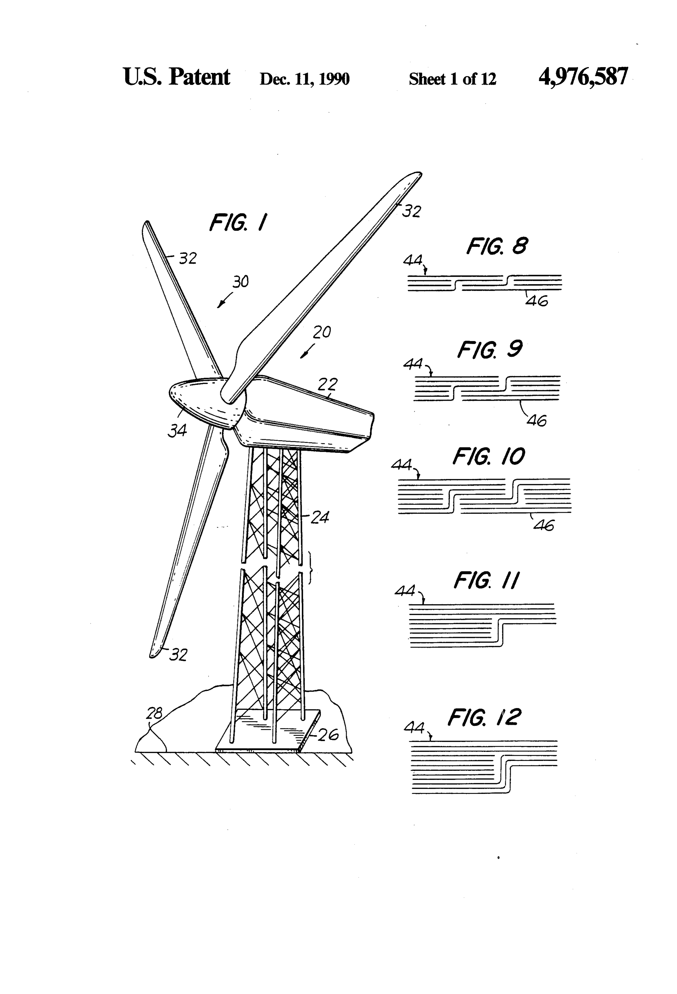
BRIEF DESCRIPTION OF THE DRAWINGS bringing the spinning rotor to a stop should an over Further objects, features and advantages of our in speed condition occur. Typically, an anemometer (not vention will become apparent upon consideration of the shown) mounted atop housing 22 monitors wind speed following detailed description in connection with the so that under severe wind conditions which could cause drawings in which: 10 damage to the rotor blades or wind turbine system, the FIG. 1 is a perspective view of a wind turbine genera housing 22 is turned so that rotor 30 is parallel to the tor having a rotor utilizing three turbine blades in ac wind, thus decreasing loads on the blades and the other cordance with the present invention; components within housing 22.
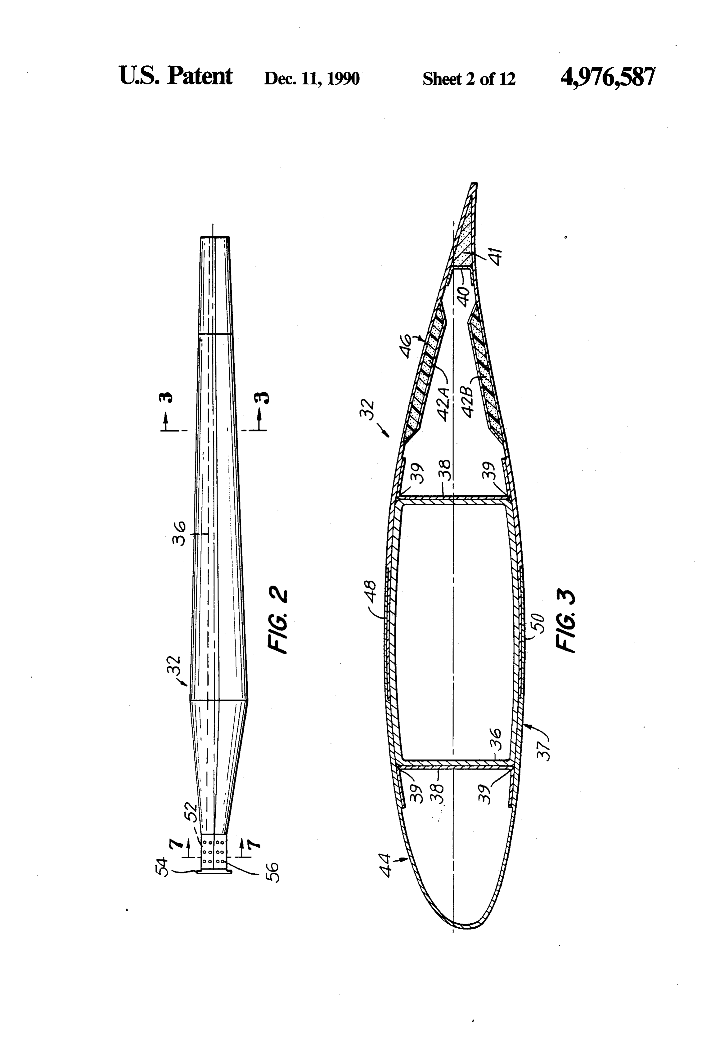
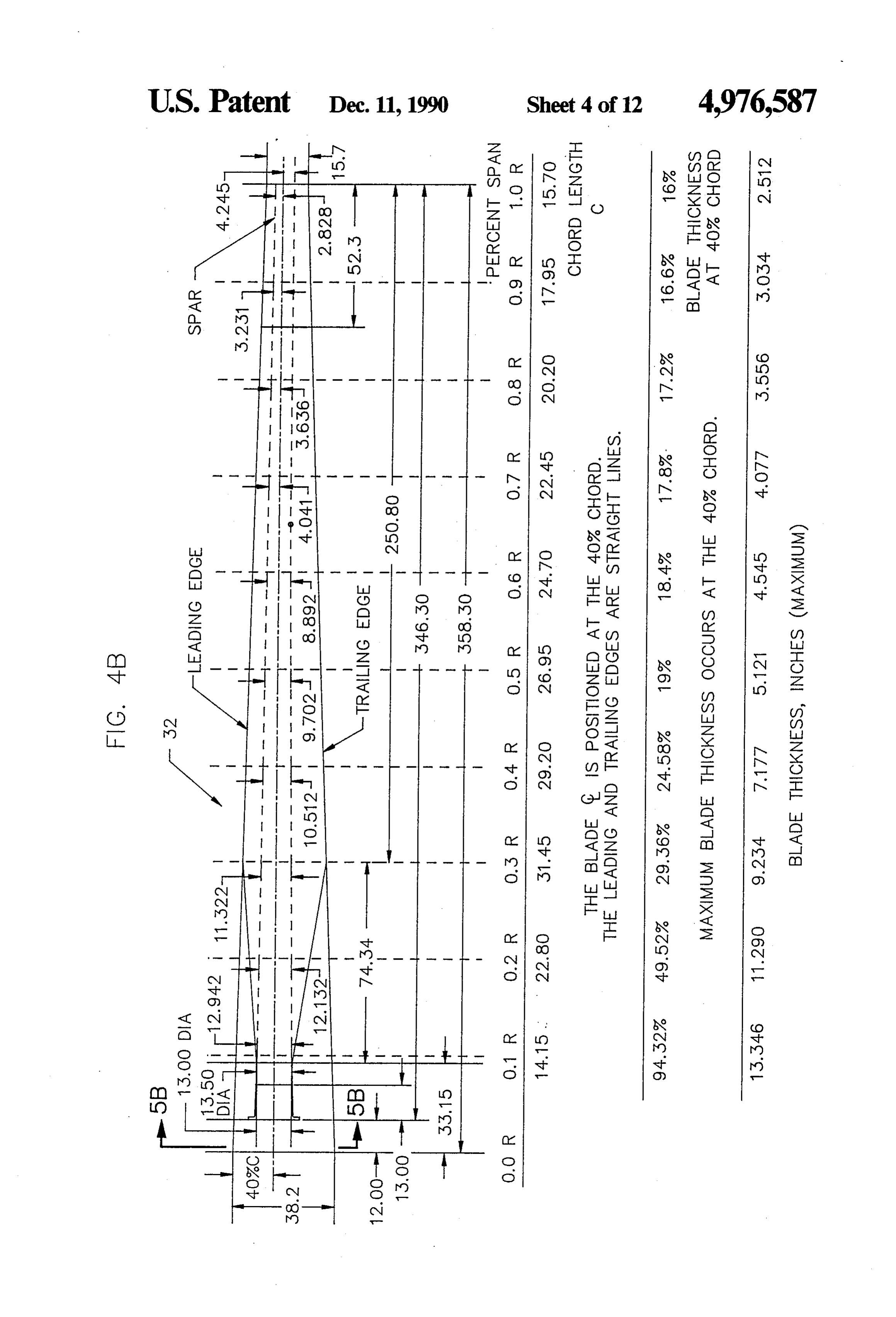
FIG. 2 is a plan view of one of the rotor blades in AIRFOIL DESIGN
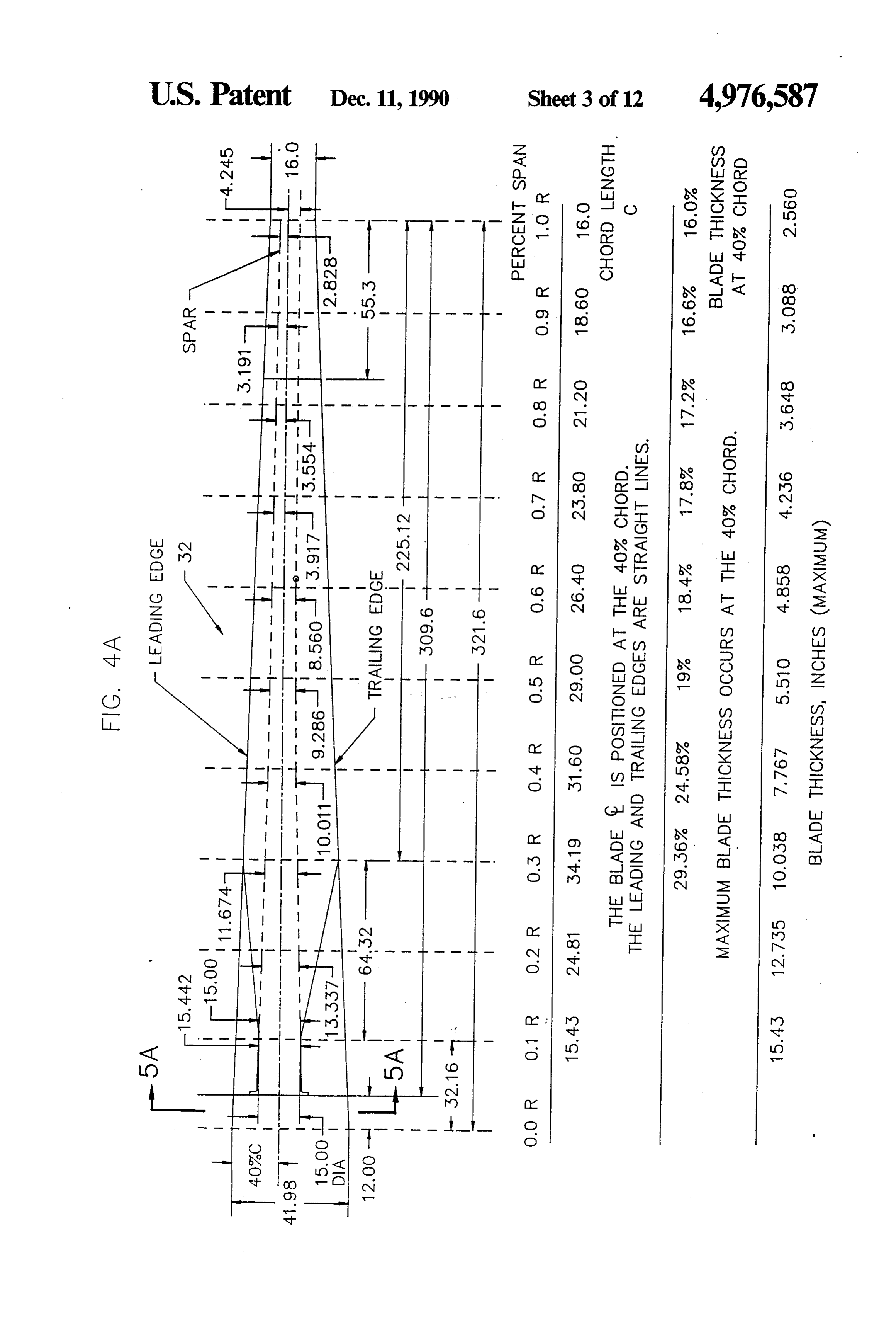
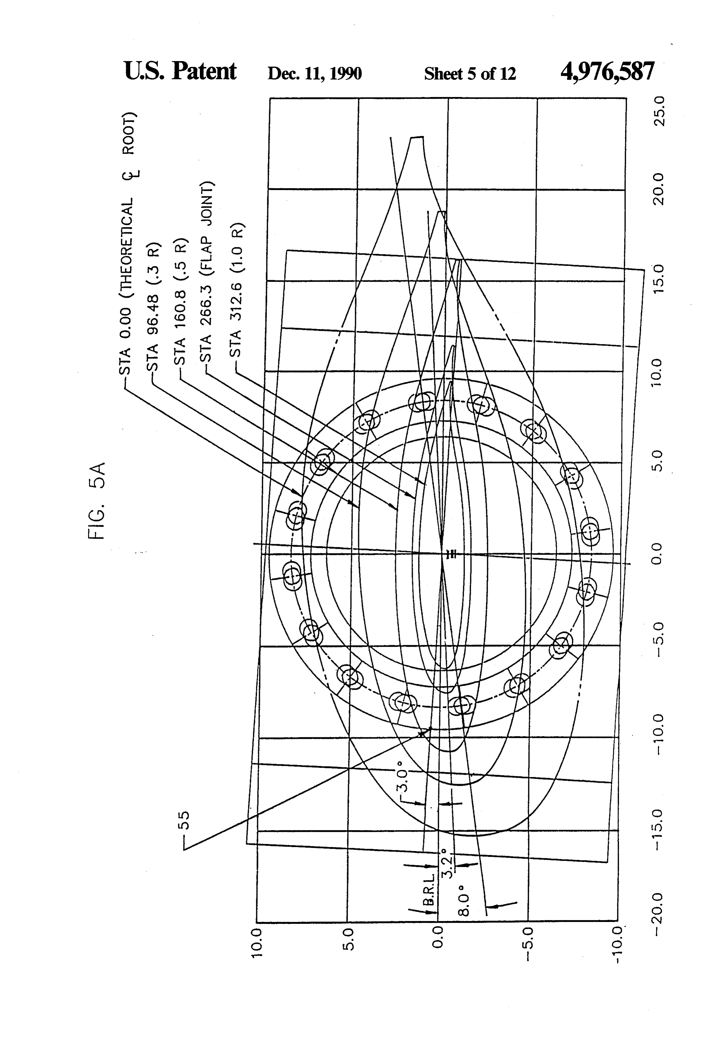
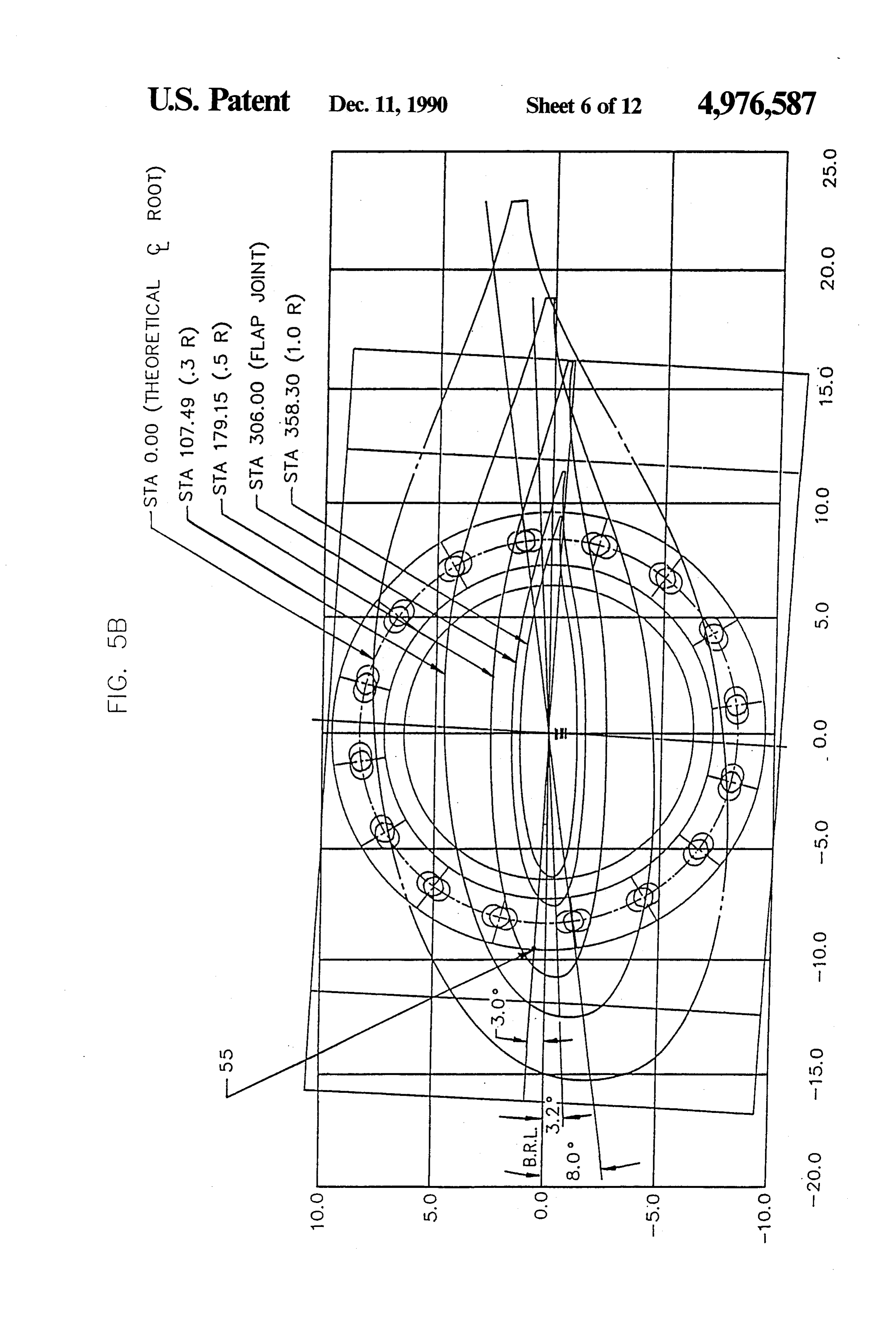
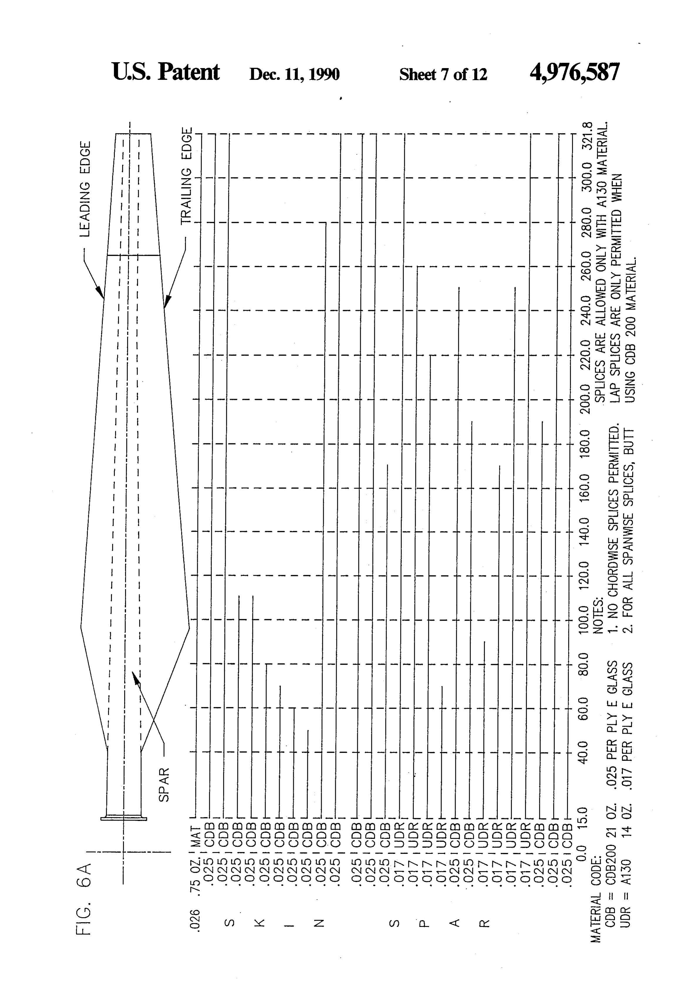
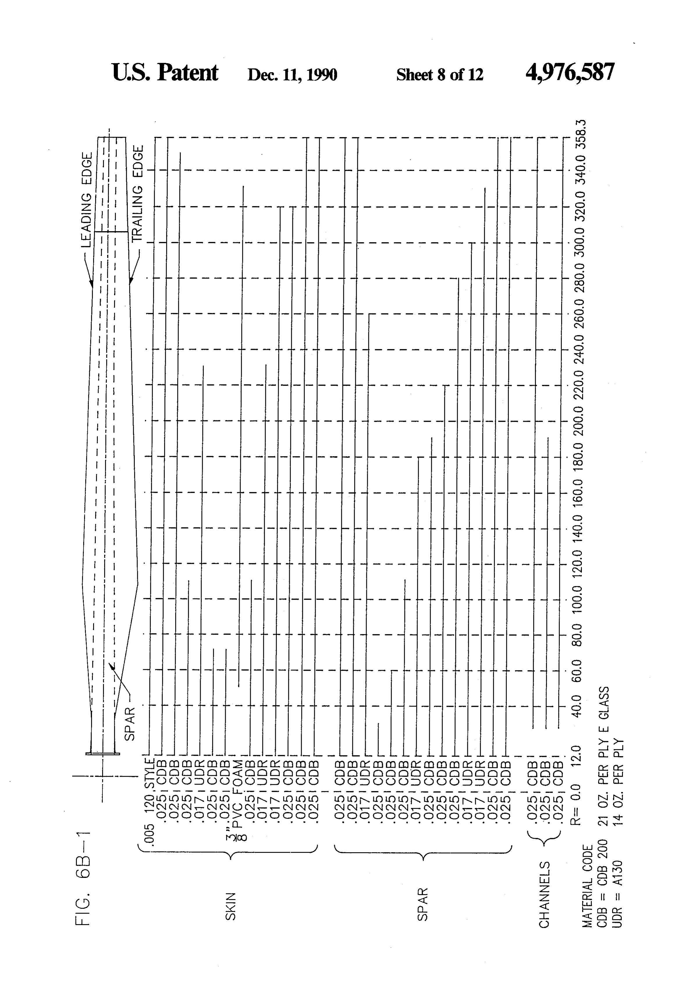
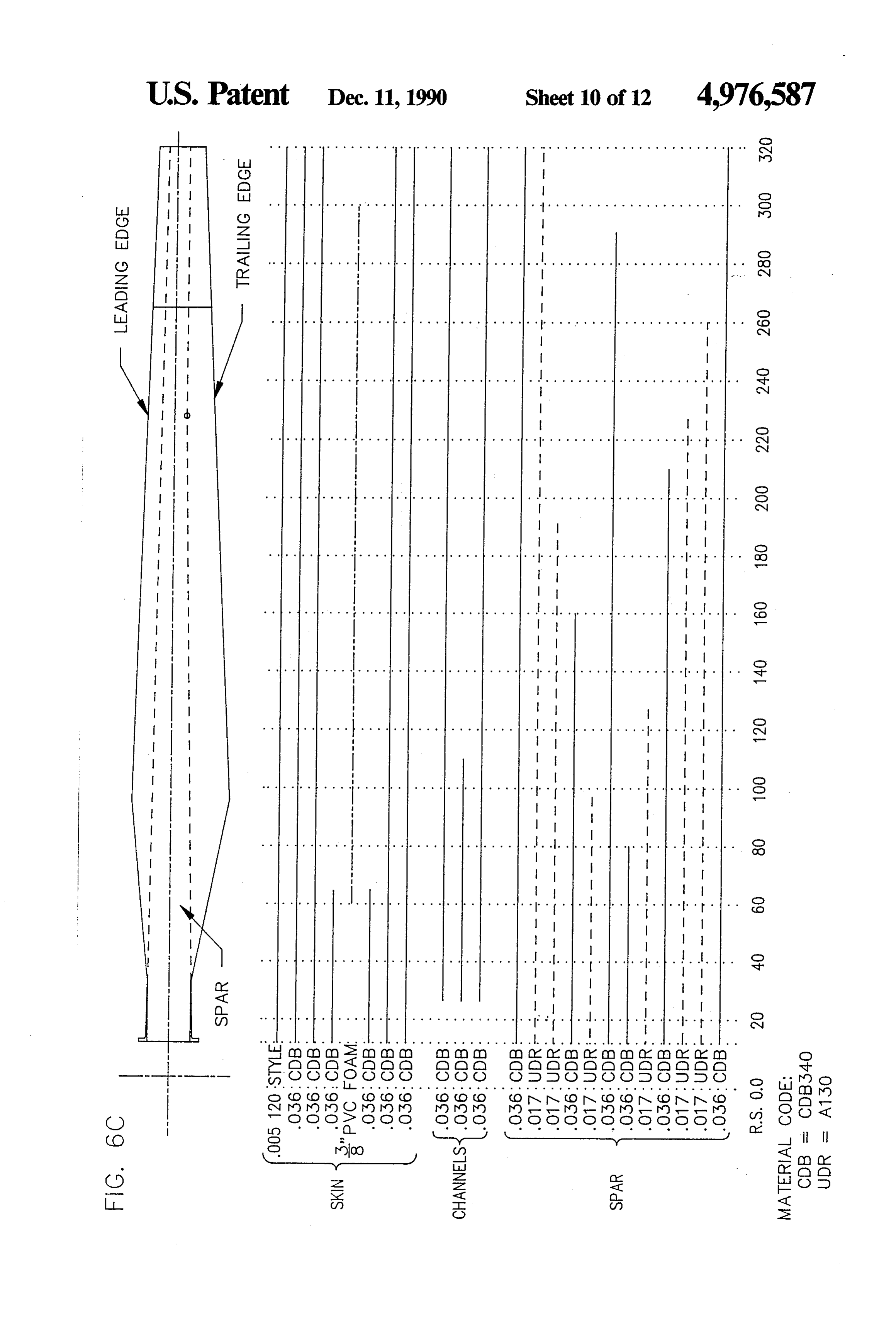
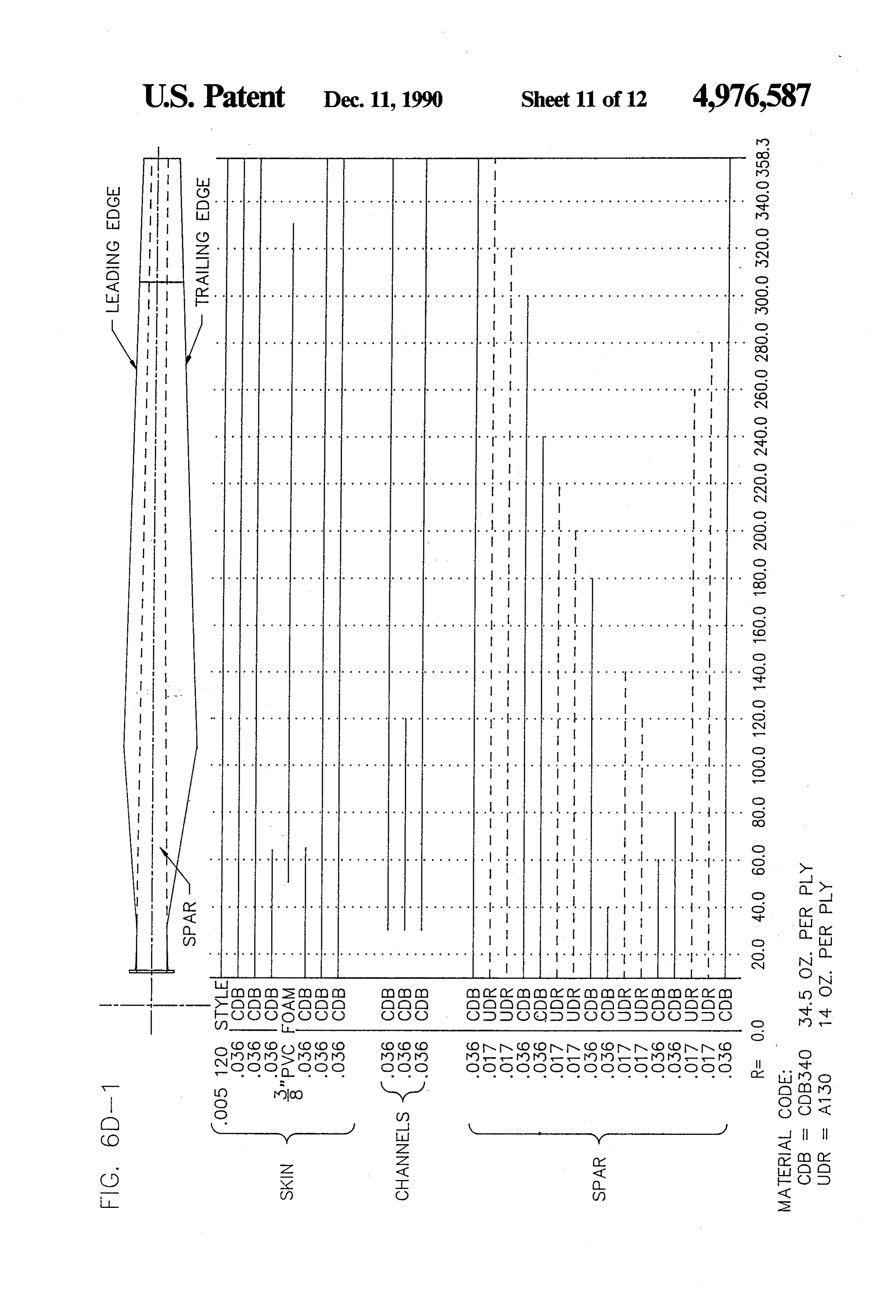
FIG. 3 is a cross-section view taken along line 3-3 of Since, in many locations, there are more hours of FIG. 2; moderate windspeeds (i.e., 20-30 mph) and fewer hours FIG. 4A and FIG. 4B are detailed dimensioned draw of high wind speeds (i.e., over 30 mph), the basic con ings showing plan, chord length and thickness for an 8.2 cept utilized in the present invention is to increase the meter blade and 9.1. meter blade, respectively, in accor 20 swept area of the blades (by using longer blades), which dance with the invention; allows for greater energy capture in a purely physical FIG. 5A and FIG. 5B are schematic views in the way. It is not at all obvious, however, that one can direction of lines 5A-5A and 5B-5B, of FIG. 4A and actually do this, because longer blades may increase FIG. 4B respectively, which represent the twist of an mechanical loads on the turbine to unacceptable levels, 8.2 meter blade and a 9.1 meter blade, respectively, of 25 may be prohibitively expensive, and may also have the invention; - shorter expected lifetimes than the shorter blades. FIG. 6A and FIG. 6B are respective laminate sched Generally, in replacing a turbine blade with one of a ules for the 8.2 meter and 9.1 meter blades in accor new design, the external features of the blade which can dance with the invention; FIG. 6B-2 contains notes be varied to control the aerodynamic characteristics associated with FIG. 6B-1; and thus the mechanical results include the following FIG. 6C and FIG. 6D-1 are respective laminate design parameters:
schedules, using a different material, for the 8.2 meter 1. Blade length;
and 9.1 meter blades in accordance with the invention; 2. Aspect ratio (i.e., the length of the chord compared FIG. 6D-2 contains notes associated with FIG. 6D-1; to the length of the blade at each position along the FIG. 7 is a cross-sectional view taken along line 7-7 35 blade);
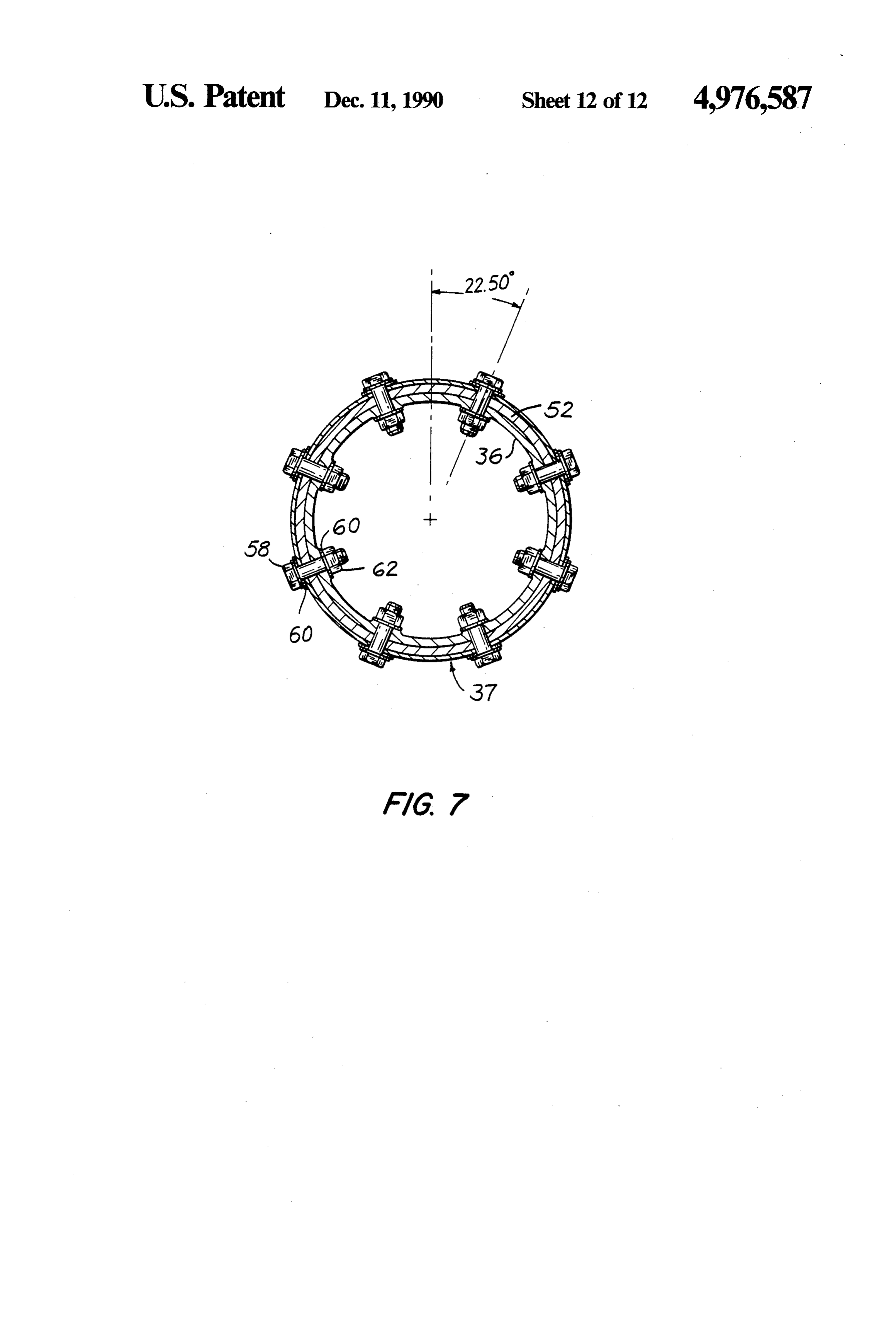
of FIG. 2 and enlarged in scale with respect to FIG. 2; 3. Thickness-to-chord ratio (i.e., the exact size of the and airfoil section at each position along the length of the FIG. 8 to FIG. 12 are schematic representations of blade); and the ply lay-up arrangements used in the blade according 4. Blade twist.
to the invention, represented in FIG. 2 and FIG. 3. 40 Various airfoil shapes are generally considered for
DETAILED DESCRIPTION OF THE
any given application. It was initially determined that
PREFERRED EMBODIMENTS
the best airfoil shape for reduced sensitivity to dirt and debris is the NASA LSC1) profile, which has the highest
The present invention is described below with refer efficiency based on the ratio of the coefficient of lift to ence to two different sizes of blades, each of which may 45 the coefficient of drag of all presently available airfoil be used in sets to make up the rotor of a wind turbine. shapes.
However, it will be understood that the principles of the In addition to determining the appropriate airfoil invention may be applied to other blade sizes used for shape to meet the objective of increased power, it is different generators. In general, the length of the blade necessary to evaluate the economics and internal struc is chosen so that the maximum aerodynamic power 50 ture of the blade to be produced in accordance with the corresponds to the maximum power rating of the gener external aerodynamic parameters.
ator (allowing for mechanical to electrical conversion It was determined that lengths of 8.2M for the V-15 losses) used in the wind turbine. turbine (which currently has a 7.5M blade) and 9.1M for Referring to FIG. 1, a wind turbine generating sys the V-17 turbine (which currently has a 8.5M blade) tem 20 includes a generator housing assembly 22 sup 55 were the maximum practical lengths to stay within the ported atop a tower 24. Tower 24 is affixed to a base26 design parameters. The size of the root attachment of which is firmly secured to the surface of the earth 28. the V-15 turbine is actually larger than that used on the Guywires (not shown) may extend from tower 24 to V-17 machine so that even though the V-15 blade is fixtures (not shown) in the earth 28 so as to secure tower shorter, care must be taken to provide a uniform transi 24 against lateral loads. 60 tion in loads along the blade. System 20 includes a turbine rotor 30 having three It was found that the thickness of the airfoil com blades 32 affixed to a central hub (not shown in FIG. 1) pared to the length of the chord should average about beneath a cone 34. The hub of rotor 30 is affixed to a 17% or less along the outboard 50% of the blade where shaft (not shown) extending longitudinally in housing most of the power is produced The range of this param 22 (perpendicular to the plane of blades 32). As is well 65 eter is from 15% at the tip to 19% at the midpoint of the known in the art, housing 22 typically includes a gear span of the blade, with 16% to 19% being the preferred box for increasing the speed of revolution of the genera range of this parameter along the span of the blade to tor drive relative to that of the shaft; a three phase allow for a smooth transfer, to the root of the blade, of
Page 17
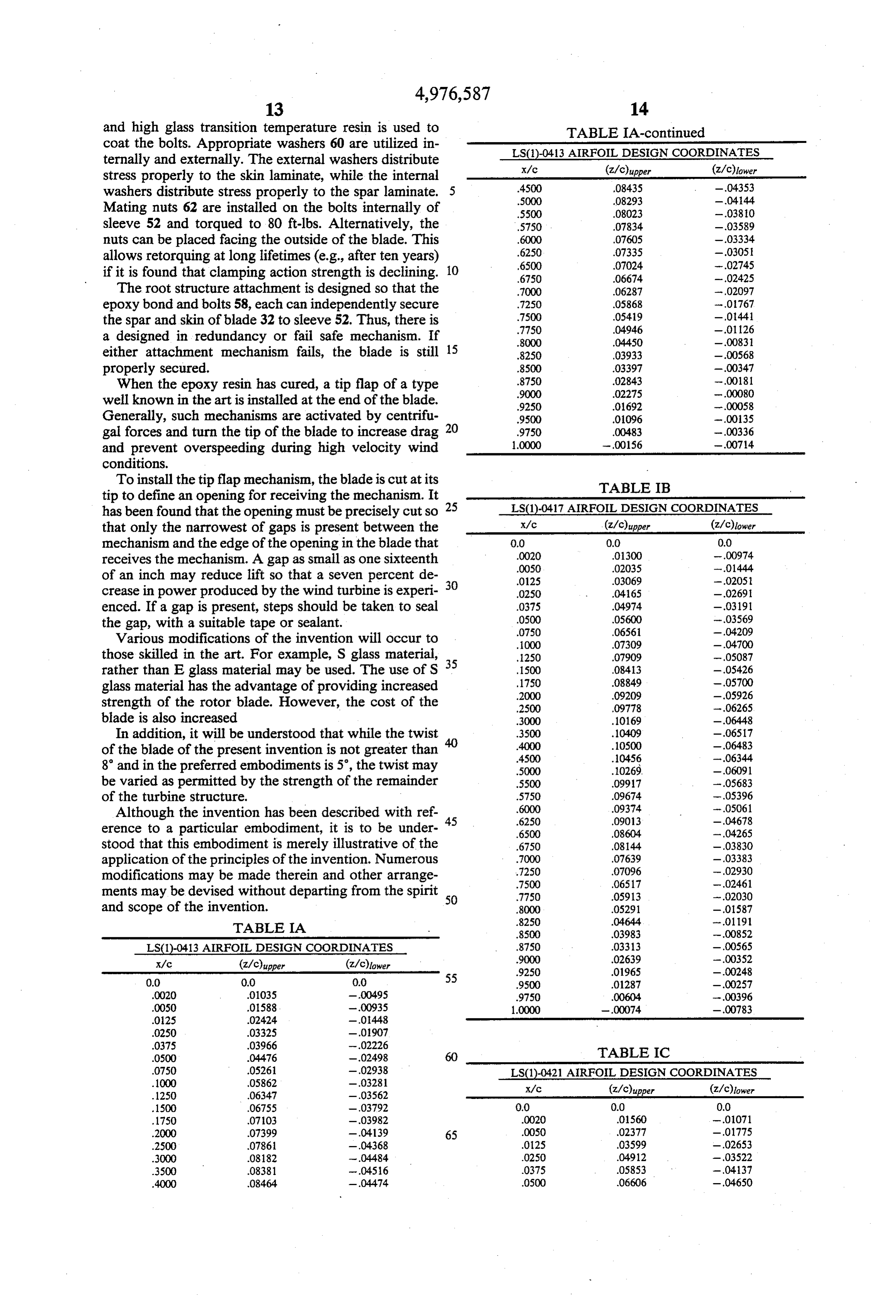
the bending moments and other loads. This is important There is no twist from the fifty percent radius station to because these blades have steel roots which have been full radius. FIG. 5A and FIG. 5B also illustrate the proven to confer superior blade longevity as compared rotational relationship of the blades and a flange 54 used with blades having plastic roots reinforced with fiber for connection to the rotor hub, as more fully described glass or fiberglass roots reinforced with steel. The suc below. Each flange 54 has a notch 55 to facilitate proper cess of steel roots is dependent on transferring operating rotational alignment of flange 54 and its respective loads on the blades uniformly from the glass-resin por blade.
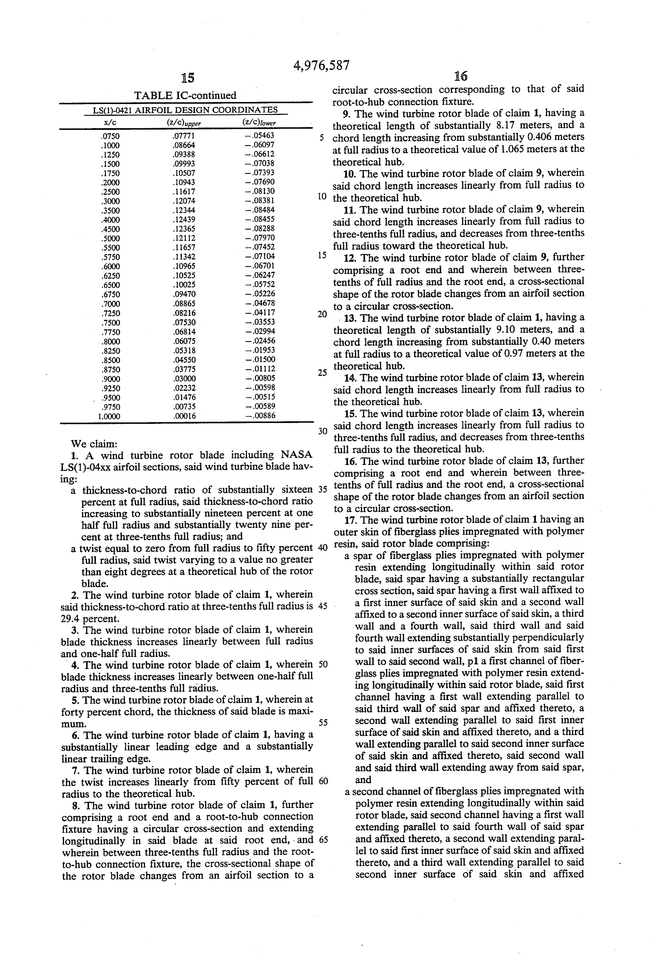
tion of the blade to the steel root and cuff area. The The precise coordinates for construction of the 8.2 M outboard airfoil shape as well as the taper in the transi and 9.1 M blades according to the invention are set tion region, and the avoidance of any sharp edges or 10 forth in Tables IA, IB and IC. The actual thickness transitions, allows these loads to be transferred uni values as a function of chord station, from leading edge formly. at 0.0 to trailing edge at 1.0000 for type LS(1)-0413, An important and surprising design determination is LS(1)-0417 and LS(1)-0421 airfoils are set forth in tables that the new blades should be only approximately 70% IA, IB and IC, respectively. It will be understood by as wide as the existing blades. The precise chord lengths 15 one skilled in the art that the actual coordinate values at which are best for each design are set forth in detail in any station may be determined by interpolating, using a FIG. 4A for the 8.2 M blade and in FIG. 4B for the 9.1 standard procedure, between the values in these three M blade. As illustrated in FIG. 4A and FIG. 4B, the tables, which are for thickness-to-chord ratios of 13%, blade centerline is positioned at the forty percent chord, 17% and 21% respectively.
where the blade is at maximum thickness. The actual 20 The projected power curves of the blades con maximum blade thickness, as a function of radius, is also structed in accordance with the invention, when ap shown in FIG. 4A and FIG. 4B. The leading and trail plied to the wind speed distributions present at the loca ing edges describe straight lines to simplify blade con tions of existing wind energy projects, show power struction, i.e., the blade has a linear taper. The slight increases ranging from 26% to 42% above prior art advantages which may be conferred by using designs 25 blade configurations.
other than a straight line design are more than offset by BLADE CONSTRUCTION additional blade construction costs due to more expen sive molds, the need for more careful lay-up of the The construction of the blades must also meet objec fiberglass and difficulties in maintaining good structural tives with regard to blade durability, quality and cost. characteristics including adequate bonding and proper 30 The use of GRP (glass reinforced polymer), with both tolerances during the manufacturing process. bidirectional and unidirectional fibers in the mat, is If the leading and trailing edges were extended in critical because unidirectional mat alone or filament ward to the center of rotation of the rotor (the theoreti wound sections do not provide as much strength per cal hub), the chord lengths would be 38.2 inches (0.970 unit weight in directions perpendicular to the direction M) for the 9.1 M blade and 41.98 inches (1.066 M) for 35 of the fibers. The use of bidirectional fiber mat allows a the 8.2 M blade. However, in accordance with the in reduction in weight while maintaining strength. vention the shape is changed, from thirty percent of full Blades are designed to weigh between 450 and 600 radius inward, from an airfoil to a tube of circular con pounds when fully assembled with flaps or other se figuration which fits into a hub connection sleeve as lected speed control devices. In addition, the center of described below. Blade length is measured from the tip 40 gravity must be within one inch of the calculated design to the theoretical hub. location so that the blades will be very closely balanced It has also been found that an 8 twist is the maximum as built.
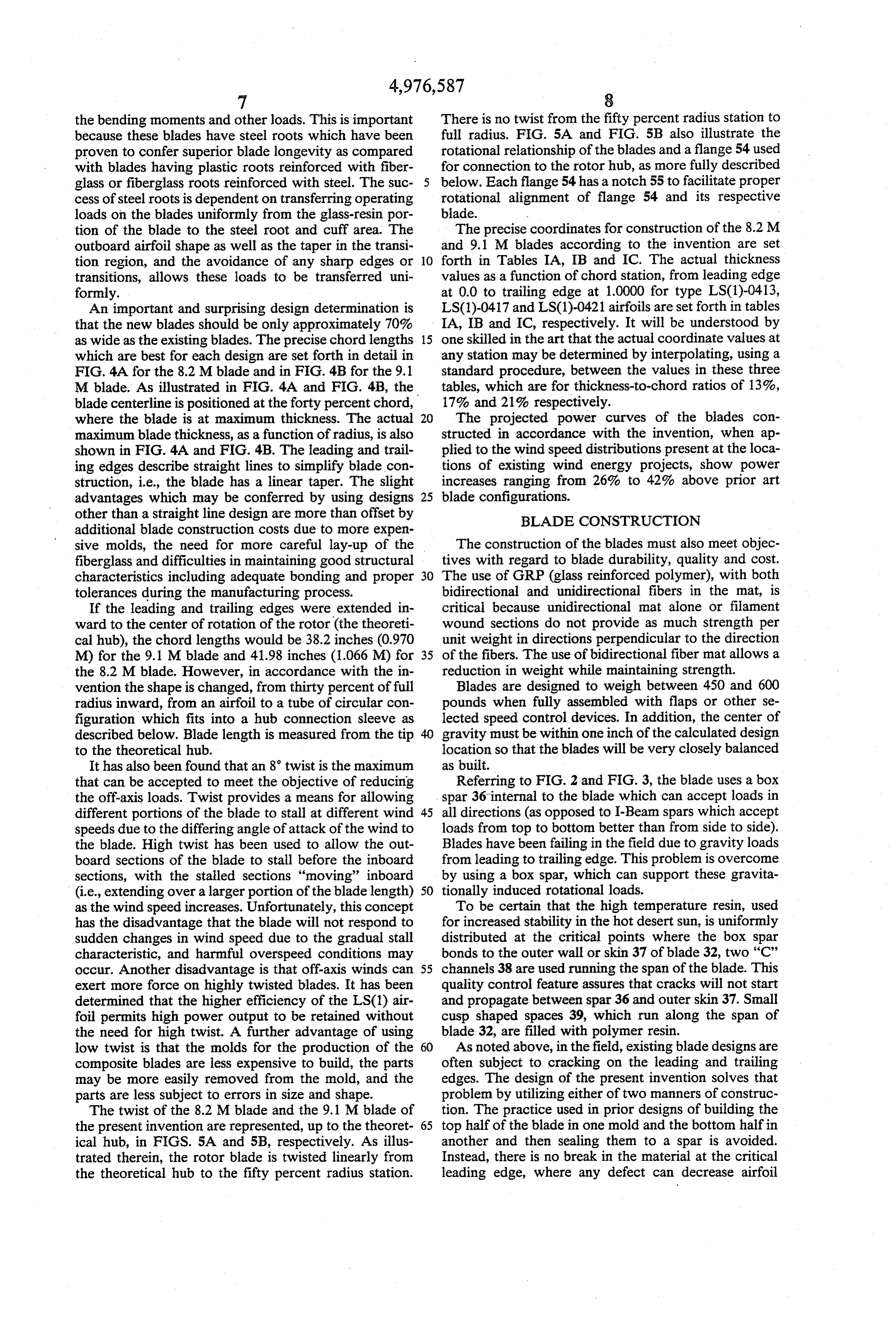
that can be accepted to meet the objective of reducing Referring to FIG. 2 and FIG. 3, the blade uses a box the off-axis loads. Twist provides a means for allowing spar 36 internal to the blade which can accept loads in different portions of the blade to stall at different wind 45 all directions (as opposed to I-Beam spars which accept speeds due to the differing angle of attack of the wind to loads from top to bottom better than from side to side). the blade. High twist has been used to allow the out Blades have been failing in the field due to gravity loads board sections of the blade to stall before the inboard from leading to trailing edge. This problem is overcome sections, with the stalled sections "moving' inboard by using a box spar, which can support these gravita (i.e., extending over a larger portion of the blade length) 50 tionally induced rotational loads. as the wind speed increases. Unfortunately, this concept To be certain that the high temperature resin, used has the disadvantage that the blade will not respond to for increased stability in the hot desert sun, is uniformly sudden changes in wind speed due to the gradual stall distributed at the critical points where the box spar characteristic, and harmful overspeed conditions may bonds to the outer wall or skin 37 of blade 32, two "C' occur. Another disadvantage is that off-axis winds can 55 channels 38 are used running the span of the blade. This exert more force on highly twisted blades. It has been quality control feature assures that cracks will not start determined that the higher efficiency of the LSC1) air and propagate between spar 36 and outer skin 37. Small foil permits high power output to be retained without cusp shaped spaces 39, which run along the span of the need for high twist. A further advantage of using blade 32, are filled with polymer resin. low twist is that the molds for the production of the 60 As noted above, in the field, existing blade designs are composite blades are less expensive to build, the parts often subject to cracking on the leading and trailing may be more easily removed from the mold, and the edges. The design of the present invention solves that parts are less subject to errors in size and shape. problem by utilizing either of two manners of construc The twist of the 8.2 M blade and the 9.1 M blade of tion. The practice used in prior designs of building the the present invention are represented, up to the theoret 65 top half of the blade in one mold and the bottom half in ical hub, in FIGS. 5A and 5B, respectively. As illus another and then sealing them to a spar is avoided. trated therein, the rotor blade is twisted linearly from Instead, there is no break in the material at the critical the theoretical hub to the fifty percent radius station. leading edge, where any defect can decrease airfoil
Page 18
efficiency. The blade is built in two sections which It is preferred that resin impregnation machines, such represent the leading edge half of the blade and the as, for example, a Venus Impregnator, be used to obtain trailing edge half of the blade. These sections are then a uniformly wetout fabric with a resin content of 45% sealed along the span of the blade adjacent the top and --5% by weight.
bottom walls of the box spar. Alternatively the entire 5 The lay-up should be done in an area which is free skin may be built as a "clam shell' which opens at the from contamination. Proper precautions should be trailing edge to allow insertion of the spar and other taken to assure that prior to use, all raw materials are internal components. Of these modes of fabrication, the stored according to the manufacturers' recommenda two section approach (front and back halves) is pre tions.
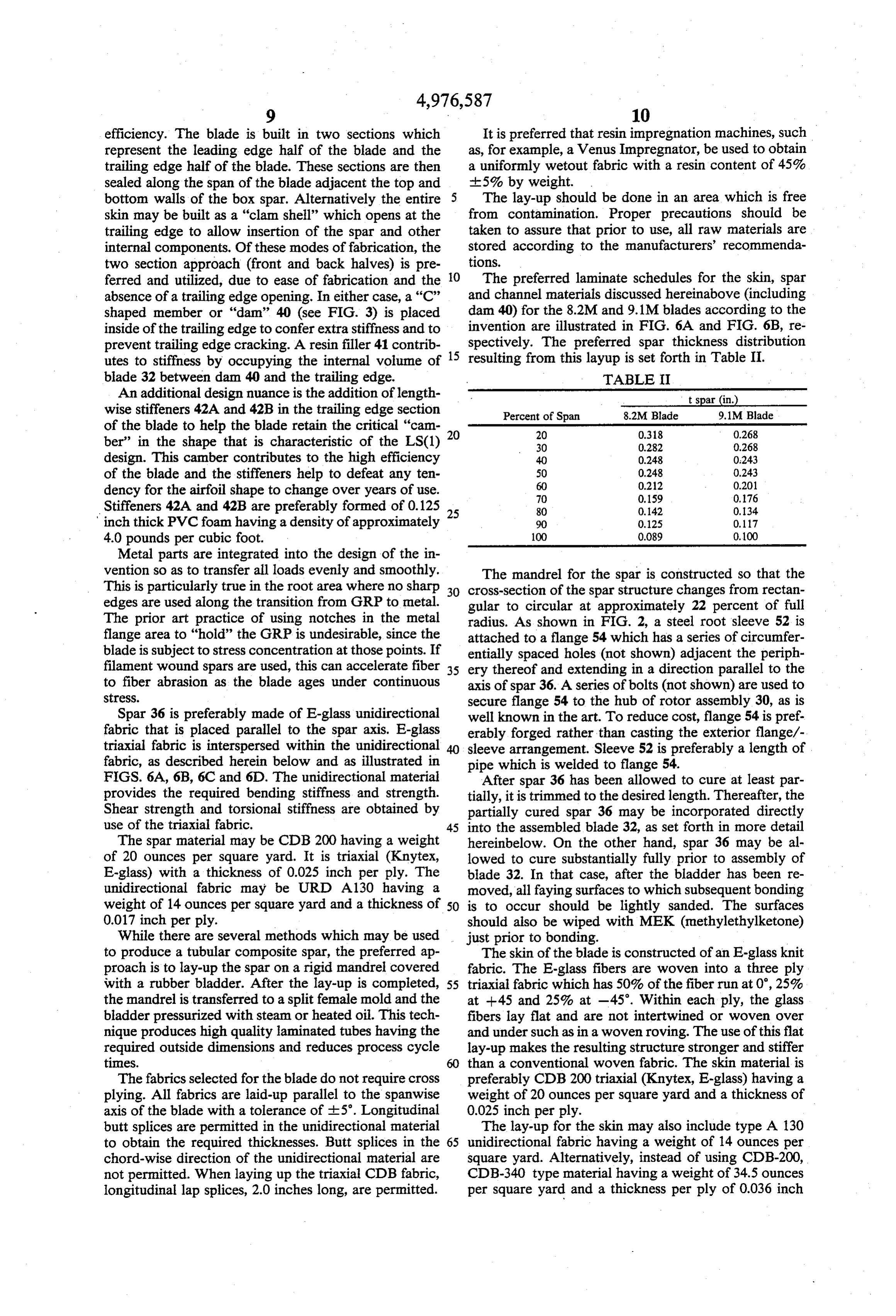
ferred and utilized, due to ease of fabrication and the O The preferred laminate schedules for the skin, spar absence of a trailing edge opening. In either case, a "C" and channel materials discussed hereinabove (including shaped member or "dam' 40 (see FIG. 3) is placed dam 40) for the 8.2M and 9.1M blades according to the inside of the trailing edge to confer extra stiffness and to invention are illustrated in FIG. 6A and FIG. 6B, re prevent trailing edge cracking. A resin filler 41 contrib 15 spectively. The preferred spar thickness distribution utes to stiffness by occupying the internal volume of resulting from this layup is set forth in Table II. blade 32 between dam 40 and the trailing edge. TABLE II An additional design nuance is the addition of length - Spain)- wise stiffeners 42A and 42B in the trailing edge section Percent of Span 8.2M Blade 9.1M Blade of the blade to help the blade retain the critical "cam 20 20 0.318 0.268 ber” in the shape that is characteristic of the LS(1) 30 0.282 0,268 design. This camber contributes to the high efficiency 40 0.248 0.243 of the blade and the stiffeners help to defeat any ten 50
dency for the airfoil shape to change over years of use. 70 0.159 0.76 Stiffeners 42A and 42B are preferably formed of 0.125 25 80 0.142 0.34 inch thick PVC foam having a density of approximately 90 0.12S 0,117 4.0 pounds per cubic foot. 100 0.089 0.100 Metal parts are integrated into the design of the in vention so as to transfer all loads evenly and smoothly. The mandrel for the spar is constructed so that the This is particularly true in the root area where no sharp 30 cross-section of the spar structure changes from rectan edges are used along the transition from GRP to metal. gular to circular at approximately 22 percent of full The prior art practice of using notches in the metal radius. As shown in FIG. 2, a steel root sleeve 52 is flange area to “hold” the GRP is undesirable, since the attached to a flange 54 which has a series of circumfer blade is subject to stress concentration at those points. If entially spaced holes (not shown) adjacent the periph filament wound spars are used, this can accelerate fiber 35 ery thereof and extending in a direction parallel to the to fiber abrasion as the blade ages under continuous axis of spar 36. A series of bolts (not shown) are used to StreSS. secure flange 54 to the hub of rotor assembly 30, as is Spar 36 is preferably made of E-glass unidirectional well known in the art. To reduce cost, flange 54 is pref fabric that is placed parallel to the spar axis. E-glass erably forged rather than casting the exterior flange/- triaxial fabric is interspersed within the unidirectional 40 sleeve arrangement. Sleeve 52 is preferably a length of fabric, as described herein below and as illustrated in pipe which is welded to flange 54. FIGS. 6A, 6B, 6C and 6D. The unidirectional material After spar 36 has been allowed to cure at least par provides the required bending stiffness and strength. tially, it is trimmed to the desired length. Thereafter, the Shear strength and torsional stiffness are obtained by partially cured spar 36 may be incorporated directly use of the triaxial fabric. 45 into the assembled blade 32, as set forth in more detail The spar material may be CDB 200 having a weight hereinbelow. On the other hand, spar 36 may be al of 20 ounces per square yard. It is triaxial (Knytex, lowed to cure substantially fully prior to assembly of E-glass) with a thickness of 0.025 inch per ply. The blade 32. In that case, after the bladder has been re unidirectional fabric may be URD A130 having a moved, all faying surfaces to which subsequent bonding weight of 14 ounces per square yard and a thickness of 50 is to occur should be lightly sanded. The surfaces 0.017 inch per ply. should also be wiped with MEK (methylethylketone) While there are several methods which may be used just prior to bonding.
to produce a tubular composite spar, the preferred ap The skin of the blade is constructed of an E-glass knit proach is to lay-up the spar on a rigid mandrel covered fabric. The E-glass fibers are woven into a three ply with a rubber bladder. After the lay-up is completed, 55 triaxial fabric which has 50% of the fiber run at 0, 25% the mandrel is transferred to a split female mold and the at --45 and 25% at -45. Within each ply, the glass bladder pressurized with steam or heated oil. This tech fibers lay flat and are not intertwined or woven over nique produces high quality laminated tubes having the and under such as in a woven roving. The use of this flat required outside dimensions and reduces process cycle lay-up makes the resulting structure stronger and stiffer times. 60 than a conventional woven fabric. The skin material is The fabrics selected for the blade do not require cross preferably CDB200 triaxial (Knytex, E-glass) having a plying. All fabrics are laid-up parallel to the spanwise weight of 20 ounces per square yard and a thickness of axis of the blade with a tolerance of 5. Longitudinal 0.025 inch per ply.
butt splices are permitted in the unidirectional material The lay-up for the skin may also include type A 130 to obtain the required thicknesses. Butt splices in the 65 unidirectional fabric having a weight of 14 ounces per chord-wise direction of the unidirectional material are square yard. Alternatively, instead of using CDB-200, not permitted. When laying up the triaxial CDB fabric, CDB-340 type material having a weight of 34.5 ounces longitudinal lap splices, 2.0 inches long, are permitted. per square yard and a thickness per ply of 0.036 inch
Page 19
may also be used. The laminate schedules for the use of to being placed in their respective molds. The polymer type CD340 material, with type UDR A130 material resin used is preferably a common industrial grade poly interspersed therein, are shown in FIG. 6C and FIG. ester having a service temperature of 160 F. While 6D for the 8.2 meter and 9.1 meter blades, respectively. epoxy resin could be used to improve strength, it is It will be understood that the particular lay-up schedule 5 more costly, and the strength provided by the use of a chosen for the spar, the skin and the "C' channels will polyester resin is sufficient for the intended application. depend on the type of material being used. When the plies making up trailing edge assembly 46 To obtain the required exterior skin smoothness and are layed up in the trailing edge mold, stiffeners 42A dimensions, female tools are preferred for the skin. Tool and 42B are placed between the appropriate plies. Any actuation may be accomplished by hydraulic or pneu- 10 excess resin is. forced from the mold.
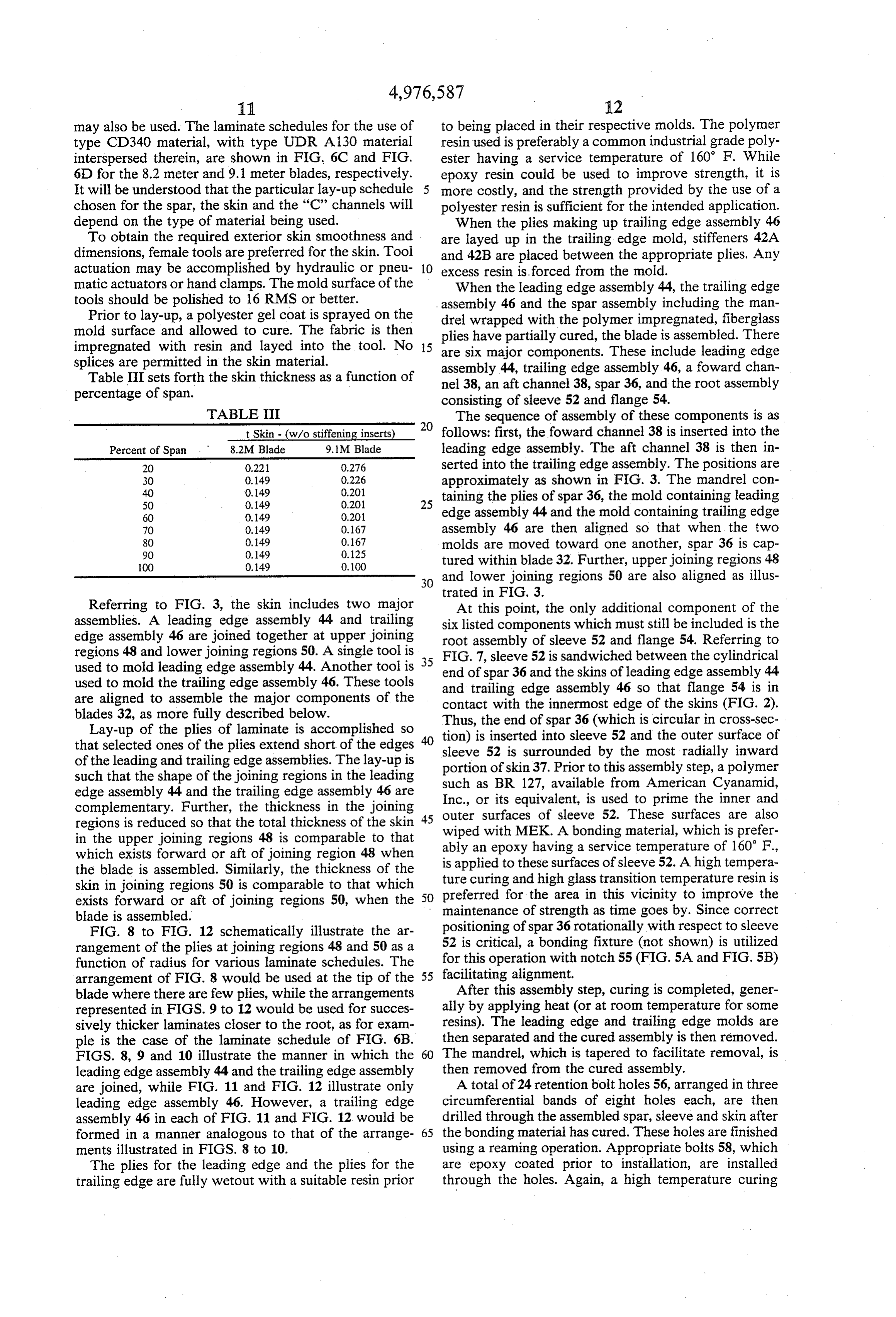
matic actuators or hand clamps. The mold surface of the When the leading edge assembly 44, the trailing edge tools should be polished to 16 RMS or better. assembly 46 and the spar assembly including the man Prior to lay-up, a polyester gel coat is sprayed on the drel wrapped with the polymer impregnated, fiberglass mold surface and allowed to cure. The fabric is then plies have partially cured, the blade is assembled. There impregnated with resin and layed into the tool. No 15 are six major components. These include leading edge splices are permitted in the skin material. assembly 44, trailing edge assembly 46, a foward chan Table III sets forth the skin thickness as a function of nel 38, an aft channel 38, spar 36, and the root assembly percentage of span. consisting of sleeve 52 and flange 54. TABLE III The sequence of assembly of these components is as t Skin - (w/o stiffening inserts) 20 follows: first, the foward channel 38 is inserted into the Percent of Span 8.2M Blade 9.1M Blade leading edge assembly. The aft channel 38 is then in 20 0.221 0.276 serted into the trailing edge assembly. The positions are 30 0.49 0.226 approximately as shown in FIG. 3. The mandrel con
taining the plies of spar 36, the mold containing leading 60 0.149 0.201. edge assembly 44 and the mold containing trailing edge 70 0.49 0.167 assembly 46 are then aligned so that when the two
molds are moved toward one another, spar 36 is cap 100 0.49 0.100 tured within blade 32. Further, upper joining regions 48 30 and lower joining regions 50 are also aligned as illus trated in FIG, 3.
Referring to FIG. 3, the skin includes two major At this point, the only additional component of the assemblies. A leading edge assembly 44 and trailing six listed components which must still be included is the edge assembly 46 are joined together at upper joining root assembly of sleeve 52 and flange 54. Referring to regions 48 and lower joining regions 50. A single tool is FIG. 7, sleeve 52 is sandwiched between the cylindrical used to mold leading edge assembly 44. Another tool is 35 end of spar 36 and the skins of leading edge assembly 44 used to mold the trailing edge assembly 46. These tools and trailing edge assembly 46 so that flange 54 is in are aligned to assemble the major components of the contact with the innermost edge of the skins (FIG. 2). blades 32, as more fully described below.
Lay-up of the plies of laminate is accomplished so Thus, the end of spar 36 (which is circular in cross-sec that selected ones of the plies extend short of the edges 40 sleeve 52inserted tion) is into sleeve 52 and the outer surface of of the leading and trailing edge assemblies. The lay-up is portion of skin 37. Prior tobythisthe is surrounded most radially inward assembly step, a polymer such that the shape of the joining regions in the leading edge assembly 44 and the trailing edge assembly 46 are such as BR 127, available from American Cyanamid, Inc., or its equivalent, is used to prime the inner and complementary. Further, the thickness in the joining outer regions is reduced so that the total thickness of the skin 45 wiped surfaces with MEK.
of sleeve 52. These surfaces are also
A bonding material, which is prefer in the upper joining regions 48 is comparable to that which exists forward or aft of joining region 48 when ably an epoxy having a service temperature of 160 F., the blade is assembled. Similarly, the thickness of the is applied to these surfaces of sleeve 52. A high tempera skin in joining regions 50 is comparable to that which ture curing and high glass transition temperature resin is preferred for the area in this vicinity to improve the exists forward or aft of joining regions 50, when the 50 maintenance of strength as time goes by. Since correct blade is assembled.
FIG. 8 to FIG. 12 schematically illustrate the ar positioning of spar 36 rotationally with respect to sleeve rangement of the plies at joining regions 48 and 50 as a 52 is critical, a bonding fixture (not shown) is utilized function of radius for various laminate schedules. The for this operation with notch 55 (FIG. 5A and FIG. 5B) arrangement of FIG. 8 would be used at the tip of the 55 facilitating alignment.
blade where there are few plies, while the arrangements After this assembly step, curing is completed, gener represented in FIGS. 9 to 12 would be used for succes ally by applying heat (or at room temperature for some sively thicker laminates closer to the root, as for exam resins). The leading edge and trailing edge molds are ple is the case of the laminate schedule of FIG. 6B. then separated and the cured assembly is then removed. FIGS. 8, 9 and 10 illustrate the manner in which the 60 The mandrel, which is tapered to facilitate removal, is leading edge assembly 44 and the trailing edge assembly then removed from the cured assembly.
are joined, while FIG. 11 and FIG. 12 illustrate only A total of 24 retention bolt holes 56, arranged in three leading edge assembly 46. However, a trailing edge circumferential bands of eight holes each, are then assembly 46 in each of FIG. 11 and FIG. 12 would be drilled through the assembled spar, sleeve and skin after formed in a manner analogous to that of the arrange- 65 the bonding material has cured. These holes are finished ments illustrated in FIGS. 8 to 10. using a reaming operation. Appropriate bolts 58, which The plies for the leading edge and the plies for the are epoxy coated prior to installation, are installed trailing edge are fully wetout with a suitable resin prior through the holes. Again, a high temperature curing
Page 20
and high glass transition temperature resin is used to TABLE IA-continued coat the bolts. Appropriate washers 60 are utilized in ternally and externally. The external washers distribute LSC1)-0413 AIRFOIL DESIGN COORDINATES - stress properly to the skin laminate, while the internal x/c (Z/c)upper (Z/c)lower washers distribute stress properly to the spar laminate. 5 4500 0843.5 --.04353 Mating nuts 62 are installed on the bolts internally of E. sleeve 52 and torqued to 80 ft-lbs. Alternatively, the 5750 07834 -03585 nuts can be placed facing the outside of the blade. This 6000 O7605 --.03334 allows retorquing at long lifetimes (e.g., after ten years) .6250 O7335 -0305 if it is found that clamping action strength is declining. 10 : : E. The root structure attachment is designed so that the 7000 06287 -02097 epoxy bond and bolts 58, each can independently secure T250 05868 -01767 the spar and skin of blade 32 to sleeve 52. Thus, there is 7500 05419 -,0441 a designed in redundancy or fail safe mechanism. If 8. either attachment mechanism fails, the blade is still 15 8250 03933 -00568 properly secured. 8500 03397 --.00347 When the epoxy resin has cured, a tip flap of a type 87.50 02843 -00181 well known in the art is installed at the end of the blade. : S. -: Generally, such mechanisms are activated by centrifu- 9500 01096 -00135 gal forces and turn the tip of the blade to increase drag 20 9750 0.0483 -00336 and prevent overspeeding during high velocity wind 1.0000 -00156 --00714 conditions.
To install the tip flap mechanism, the blade is cut at its TABLE IB tip to define an opening for receiving the mechanism. It A has been found that the opening must be precisely cut so ? LS(1)-0417 AIRFOIL DESIGN COORDINATES that only the narrowest of gaps is present between the x/c (Z/c)upper (Z/c)lower mechanism and the edge of the opening in the blade that 0.0 O.O O.O receives the mechanism. A gap as small as one sixteenth .0020 0300 --OO974 of an inch may reduce lift so that a seven percent de- : G 3. crease in power produced by the wind turbine is experi- O250 0465 -0269i enced. If a gap is present, steps should be taken to seal O375 04974 --,0319 the gap, with a suitable tape or sealant. 0500 OS600 ...03569 Various modifications of the invention will occur to g: -: those skilled in the art. For example, S glass material, 250 07509 .05087 rather than Eglass material may be used. The use of S 35 1500 0843 -.05426 glass material has the advantage of providing increased 1750 .08849 E: strength of the rotor blade. However, the cost of the 2000
blade is also increased .3000 .10169 -.06448 In addition, it will be understood that while the twist 40 3500 104.09 --.0657 of the blade of the present invention is not greater than : s: 8 and in the preferred embodiments is 5, the twist may 5000 10265 66 be varied as permitted by the strength of the remainder 5500 099.17 -.05683 of the turbine structure. 5750 O9674 -05396 Although the invention has been described with ref- 45 : : E. erence to a particular embodiment, it is to be under- 2. 08604 6.65 stood that this embodiment is merely illustrative of the 6750 .08144 .03830 application of the principles of the invention. Numerous 7000 07639 --.03383 modifications may be made therein and other arrange- 5. g -: ments may be devised without departing from the spirit 50 : 6553 500 and scope of the invention. 8000 05291 -01587
TABLE LA 8500 03983 -00852
LS(1)-0413 AIRFOIL DESIGN COORDINATES .8750 03313 -.00565 x/c Z/c Zac 9000 02639 -00352 (Z/c)upper (Z/c)lower 55 92.50 0.1965 -.00248
O.O 0.0 0.0 9500 .01287 -.00257 .0020 01.035 --00495 9750 00604 ---.00396 0.050 0.588 -00935 1.0000 -00074 --,00.783
0500 04476 --.02498 60 TABLE IC
I E. g LS(1)-0421 AIRFOIL DESIGN COORDINATES lso 0637 6:56: x/c (Z/c)upper (Z/c)lower 1500 06755 -.03792 0.0 O.O 0.0 1750 07.03 --,03982 OO20 .01560 -01071 2000 07399 --,04139 65 00:50 02377 -01775 2500 0786 -.04368 0.25 0.3599 .02653 .3000 .08182 -.04484 O250 0.4912 -,03522 3500 .08381 -.0456 O375 05853 -0437 4000 .08464 --,04474 OSOO 06606 --,04650
Page 21
TABLE IC-continued circular cross-section corresponding to that of said root-to-hub connection fixture.
LS(1)-0421 AIRFOIL DESIGN COORDINATES 9. The wind turbine rotor blade of claim 1, having a x/c (z/c)upper (Z/c)lower theoretical length of substantially 8.17 meters, and a
chord length increasing from substantially 0.406 meters 1250 .09388 -.06612 at full radius to a theoretical value of 1.065 meters at the ,500 09993 -07038 theoretical hub.
10. The wind turbine rotor blade of claim 9, wherein 2500 11617 -.0830 said chord length increases linearly from full radius to 3000 .12074 -.08381 10 the theoretical hub.
3500 .12344 -,08484 11. The wind turbine rotor blade of claim 9, wherein 4000 12439 - 08455 said chord length increases linearly from full radius to
5000 12112 -07970 three-tenths full radius, and decreases from three-tenths 5500 1657 -.07452 full radius toward the theoretical hub.
5750 1342 -0704. 15 12. The wind turbine rotor blade of claim 9, further
.6250 10525 -0.6247 comprising a root end and wherein between three 6500 ..10025 -.05752 tenths of full radius and the root end, a cross-sectional 6750 .09470 -,05226 shape of the rotor blade changes from an airfoil section 7000 .08865 -04678 to a circular cross-section.
.7500 0.7530 -03553 13. The wind turbine rotor blade of claim 1, having a 7750 06814 -.02994 theoretical length of substantially 9.10 meters, and a
chord length increasing from substantially 0.40 meters 8500 .04550 --.0500 at full radius to a theoretical value of 0.97 meters at the
theoretical hub.
9000 03000 --,00805 14. The wind turbine rotor blade of claim 13, wherein 92.50 .02232 -00598 said chord length increases linearly from full radius to
9750 0.0735 -.00589 the theoretical hub.
1.0000 .00016 -00886 15. The wind turbine rotor blade of claim 13, wherein 30 said chord length increases linearly from full radius to
We claim: three-tenths full radius, and decreases from three-tenths full radius to the theoretical hub.
1. A wind turbine rotor blade including NASA 16. The wind turbine rotor blade of claim 13, further LS(1)-04xx airfoil sections, said wind turbine blade hav comprising a root end and wherein between three ing:
tenths of full radius and the root end, a cross-sectional a thickness-to-chord ratio of substantially sixteen 35 shape of the rotor blade changes from an airfoil section percent at full radius, said thickness-to-chord ratio to a circular increasing to substantially nineteen percent at one cross-section.
half full radius and substantially twenty nine per outer 17. The wind turbine rotor blade of claim 1 having an cent at three-tenths full radius; and skin of fiberglass plies impregnated with polymer resin, a twist equal to zero from full radius to fifty percent 40 a sparsaid rotor blade comprising:
full radius, said twist varying to a value no greater of fiberglass plies impregnated with polymer than eight degrees at a theoretical hub of the rotor resin extending longitudinally within said rotor blade. blade, said spar having a substantially rectangular 2. The wind turbine rotor blade of claim 1, wherein cross section, said spar having a first wall affixed to said thickness-to-chord ratio at three-tenths full radius is 45 . a first inner surface of said skin and a second wall 29.4 percent. affixed to a second inner surface of said skin, a third 3. The wind turbine rotor blade of claim 1, wherein wall and a fourth wall, said third wall and said blade thickness increases linearly between full radius fourth wall extending substantially perpendicularly and one-half full radius. to said inner surfaces of said skin from said first 4. The wind turbine rotor blade of claim 1, wherein 50 wall to said second wall, p1 a first channel of fiber blade thickness increases linearly between one-half full glass plies impregnated with polymer resin extend radius and three-tenths full radius. ing longitudinally within said rotor blade, said first 5. The wind turbine rotor blade of claim 1, wherein at channel having a first wall extending parallel to forty percent chord, the thickness of said blade is maxi said third wall of said spar and affixed thereto, a U. 55 second wall extending parallel to said first inner 6. The wind turbine rotor blade of claim 1, having a surface of said skin and affixed thereto, and a third substantially linear leading edge and a substantially wall extending parallel to said second inner surface linear trailing edge. of said skin and affixed thereto, said second wall 7. The wind turbine rotor blade of claim 1, wherein and said third wall extending away from said spar, the twist increases linearly from fifty percent of full 60 and radius to the theoretical hub. a second channel of fiberglass plies impregnated with 8. The wind turbine rotor blade of claim 1, further polymer resin extending longitudinally within said comprising a root end and a root-to-hub connection rotor blade, said second channel having a first wall fixture having a circular cross-section and extending extending parallel to said fourth wall of said spar longitudinally in said blade at said root end, . and 65 and affixed thereto, a second wall extending paral wherein between three-tenths full radius and the root lel to said first inner surface of said skin and affixed to-hub connection fixture, the cross-sectional shape of thereto, and a third wall extending parallel to said the rotor blade changes from an airfoil section to a second inner surface of said skin and affixed
Page 22
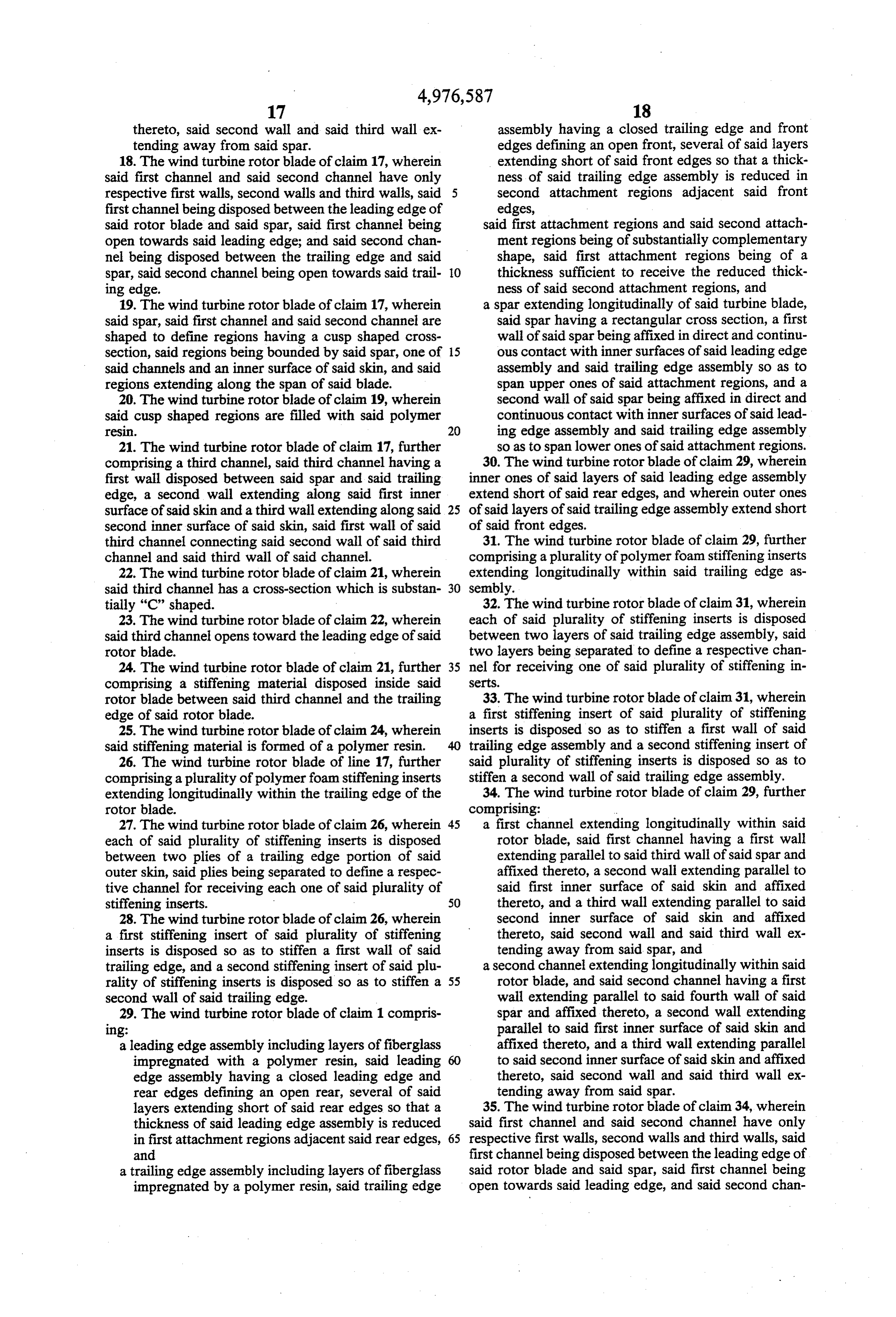
thereto, said second wall and said third wall ex assembly having a closed trailing edge and front tending away from said spar. edges defining an open front, several of said layers 18. The wind turbine rotor blade of claim 17, wherein extending short of said front edges so that a thick said first channel and said second channel have only ness of said trailing edge assembly is reduced in respective first walls, second walls and third walls, said 5 second attachment regions adjacent said front first channel being disposed between the leading edge of edges, said rotor blade and said spar, said first channel being said first attachment regions and said second attach open towards said leading edge; and said second chan ment regions being of substantially complementary nel being disposed between the trailing edge and said shape, said first attachment regions being of a spar, said second channel being open towards said trail O thickness sufficient to receive the reduced thick ing edge. ness of said second attachment regions, and 19. The wind turbine rotor blade of claim 17, wherein a spar extending longitudinally of said turbine blade, said spar, said first channel and said second channel are said spar having a rectangular cross section, a first shaped to define regions having a cusp shaped cross wall of said spar being affixed in direct and continu section, said regions being bounded by said spar, one of 15 ous contact with inner surfaces of said leading edge said channels and an inner surface of said skin, and said assembly and said trailing edge assembly so as to regions extending along the span of said blade. span upper ones of said attachment regions, and a 20. The wind turbine rotor blade of claim 19, wherein second wall of said spar being affixed in direct and said cusp shaped regions are filled with said polymer continuous contact with inner surfaces of said lead reS1. 20 ing edge assembly and said trailing edge assembly 21. The wind turbine rotor blade of claim 17, further so as to span lower ones of said attachment regions. comprising a third channel, said third channel having a 30. The wind turbine rotor blade of claim 29, wherein first wall disposed between said spar and said trailing inner ones of said layers of said leading edge assembly edge, a second wall extending along said first inner extend short of said rear edges, and wherein outer ones surface of said skin and a third wall extending along said 25 of said layers of said trailing edge assembly extend short second inner surface of said skin, said first wall of said of said front edges.
third channel connecting said second wall of said third 31. The wind turbine rotor blade of claim 29, further channel and said third wall of said channel. comprising a plurality of polymer foam stiffening inserts 22. The wind turbine rotor blade of claim 21, wherein extending longitudinally within said trailing edge as said third channel has a cross-section which is substan 30 sembly.
tially "C" shaped. 32. The wind turbine rotor blade of claim 31, wherein 23. The wind turbine rotor blade of claim 22, wherein each of said plurality of stiffening inserts is disposed said third channel opens toward the leading edge of said between two layers of said trailing edge assembly, said rotor blade. two layers being separated to define a respective chan 24. The wind turbine rotor blade of claim 21, further 35 nel for receiving one of said plurality of stiffening in comprising a stiffening material disposed inside said setts.
rotor blade between said third channel and the trailing 33. The wind turbine rotor blade of claim 31, wherein edge of said rotor blade. a first stiffening insert of said plurality of stiffening 25. The wind turbine rotor blade of claim 24, wherein inserts is disposed so as to stiffen a first wall of said said stiffening material is formed of a polymer resin. trailing edge assembly and a second stiffening insert of 26. The wind turbine rotor blade of line 17, further said plurality of stiffening inserts is disposed so as to comprising a plurality of polymer foam stiffening inserts stiffen a second wall of said trailing edge assembly. extending longitudinally within the trailing edge of the 34. The wind turbine rotor blade of claim 29, further rotor blade. comprising:
27. The wind turbine rotor blade of claim 26, wherein 45 a first channel extending longitudinally within said each of said plurality of stiffening inserts is disposed rotor blade, said first channel having a first wall between two plies of a trailing edge portion of said extending parallel to said third wall of said spar and outer skin, said plies being separated to define a respec affixed thereto, a second wall extending parallel to tive channel for receiving each one of said plurality of said first inner surface of said skin and affixed stiffening inserts. 50 thereto, and a third wall extending parallel to said 28. The wind turbine rotor blade of claim 26, wherein second inner surface of said skin and affixed a first stiffening insert of said plurality of stiffening thereto, said second wall and said third wall ex inserts is disposed so as to stiffen a first wall of said tending away from said spar, and trailing edge, and a second stiffening insert of said plu a second channel extending longitudinally within said rality of stiffening inserts is disposed so as to stiffen a 55 rotor blade, and said second channel having a first second wall of said trailing edge. wall extending parallel to said fourth wall of said 29. The wind turbine rotor blade of claim 1 compris spar and affixed thereto, a second wall extending Ing: parallel to said first inner surface of said skin and a leading edge assembly including layers offiberglass affixed thereto, and a third wall extending parallel impregnated with a polymer resin, said leading 60 to said second inner surface of said skin and affixed edge assembly having a closed leading edge and thereto, said second wall and said third wall ex rear edges defining an open rear, several of said tending away from said spar.
layers extending short of said rear edges so that a 35. The wind turbine rotor blade of claim 34, wherein thickness of said leading edge assembly is reduced said first channel and said second channel have only in first attachment regions adjacent said rear edges, 65 respective first walls, second walls and third walls, said and first channel being disposed between the leading edge of a trailing edge assembly including layers of fiberglass said rotor blade and said spar, said first channel being impregnated by a polymer resin, said trailing edge open towards said leading edge, and said second chan
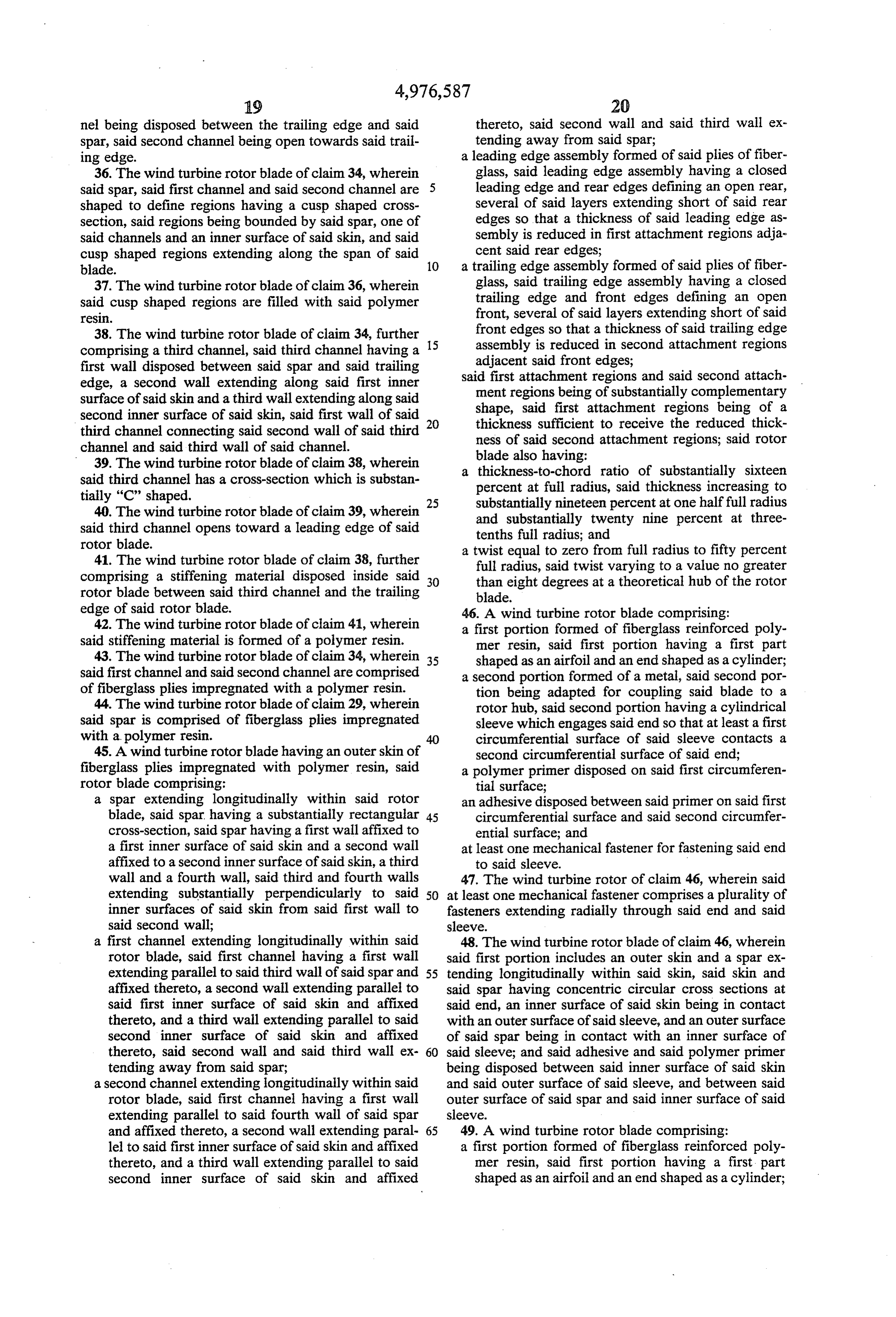
Page 23
nel being disposed between the trailing edge and said thereto, said second wall and said third wall ex spar, said second channel being open towards said trail tending away from said spar; ing edge. a leading edge assembly formed of said plies of fiber 36. The wind turbine rotor blade of claim 34, wherein glass, said leading edge assembly having a closed said spar, said first channel and said second channel are leading edge and rear edges defining an open rear, shaped to define regions having a cusp shaped cross several of said layers extending short of said rear section, said regions being bounded by said spar, one of edges so that a thickness of said leading edge as said channels and an inner surface of said skin, and said sembly is reduced in first attachment regions adja cusp shaped regions extending along the span of said cent said rear edges;
blade. 10 a trailing edge assembly formed of said plies of fiber 37. The wind turbine rotor blade of claim 36, wherein glass, said trailing edge assembly having a closed said cusp shaped regions are filled with said polymer trailing edge and front edges defining an open St. front, several of said layers extending short of said 38. The wind turbine rotor blade of claim 34, further front edges so that a thickness of said trailing edge comprising a third channel, said third channel having a 15 assembly is reduced in second attachment regions first wall disposed between said spar and said trailing adjacent said front edges; edge, a second wall extending along said first inner said first attachment regions and said second attach surface of said skin and a third wall extending along said ment regions being of substantially complementary second inner surface of said skin, said first wall of said shape, said first attachment regions being of a thickness sufficient to receive the reduced thick third channel connecting said second wall of said third 20 ness of said second attachment regions; said rotor channel and said third wall of said channel.
39. The wind turbine rotor blade of clain 38, wherein blade also having:
said third channel has a cross-section which is substan a thickness-to-chord ratio of substantially sixteen tially "C" shaped. percent at full radius, said thickness increasing to 40. The wind turbine rotor blade of claim 39, wherein 25 substantially nineteen percent at one half full radius said third channel opens toward a leading edge of said and substantially twenty nine percent at three rotor blade. tenths full radius; and 41. The wind turbine rotor blade of claim 38, further a twist equal to zero from full radius to fifty percent comprising a stiffening material disposed inside said 30 full radius, said twist varying to a value no greater rotor blade between said third channel and the trailing than eight degrees at a theoretical hub of the rotor blade.
edge of said rotor blade. 46. A wind turbine rotor blade comprising: 42. The wind turbine rotor blade of claim 41, wherein a first portion formed of fiberglass reinforced poly said stiffening material is formed of a polymer resin. mer resin, said first portion having a first part 43. The wind turbine rotor blade of claim 34, wherein 35 shaped as an airfoil and an end shaped as a cylinder; said first channel and said second channel are comprised a second portion formed of a metal, said second por of fiberglass plies impregnated with a polymer resin. tion being adapted for coupling said blade to a 44. The wind turbine rotor blade of claim 29, wherein rotor hub, said second portion having a cylindrical said spar is comprised of fiberglass plies impregnated sleeve which engages said end so that at least a first with a polymer resin. 40 circumferential surface of said sleeve contacts a 45. A wind turbine rotor blade having an outer skin of second circumferential surface of said end; fiberglass plies impregnated with polymer resin, said a polymer primer disposed on said first circumferen rotor blade comprising: tial surface;
a spar extending longitudinally within said rotor an adhesive disposed between said primer on said first blade, said spar, having a substantially rectangular 45 circumferential surface and said second circumfer cross-section, said spar having a first wall affixed to ential surface; and a first inner surface of said skin and a second wall at least one mechanical fastener for fastening said end affixed to a second inner surface of said skin, a third to said sleeve.
wall and a fourth wall, said third and fourth walls 47. The wind turbine rotor of claim 46, wherein said extending substantially perpendicularly to said 50 at least one mechanical fastener comprises a plurality of inner surfaces of said skin from said first wall to fasteners extending radially through said end and said said second wall; sleeve.
a first channel extending longitudinally within said 48. The wind turbine rotor blade of claim 46, wherein rotor blade, said first channel having a first wall said first portion includes an outer skin and a spar ex extending parallel to said third wall of said spar and 55 tending longitudinally within said skin, said skin and affixed thereto, a second wall extending parallel to said spar having concentric circular cross sections at said first inner surface of said skin and affixed said end, an inner surface of said skin being in contact thereto, and a third wall extending parallel to said with an outer surface of said sleeve, and an outer surface second inner surface of said skin and affixed of said spar being in contact with an inner surface of thereto, said second wall and said third wall ex 60 said sleeve; and said adhesive and said polymer primer tending away from said spar; being disposed between said inner surface of said skin a second channel extending longitudinally within said and said outer surface of said sleeve, and between said rotor blade, said first channel having a first wall outer surface of said spar and said inner surface of said extending parallel to said fourth wall of said spar sleeve.
and affixed thereto, a second wall extending paral 65 49. A wind turbine rotor blade comprising: lel to said first inner surface of said skin and affixed a first portion formed of fiberglass reinforced poly thereto, and a third wall extending parallel to said mer resin, said first portion having a first part second inner surface of said skin and affixed shaped as an airfoil and an end shaped as a cylinder;
Page 24
a second portion formed of a metal, said second por wherein said first portion includes an outer skin and a tion being adapted for coupling said blade to a spar extending longitudinally within said skin, said rotor hub, said second portion having a cylindrical skin and said spar having concentric circular cross sections at said end, an inner surface of said skin sleeve which engages said end so that at least a first being in contact with an outer surface of said circumferential surface of said end; sleeve, and an outer surface of said spar being in an adhesive disposed between said first circumferen contact with an inner surface of said sleeve; and tial surface and said second circumferential surface; said adhesive being disposed between said inner surface of said skin and said outer surface of said and 10 sleeve, and between said outer surface of said spar at least one mechanical fastener for fastening said end and said inner surface of said sleeve.
to said sleeve;
Provenance
- Collection
- Cited prior art
- Original PDF
- patentimages.storage.googleapis.com →
- Filed
- 1988-07-20
- Pages
- 24
- Method
- pdftotext (the PDF's own text layer) + pdftoppm 300dpi page scans
- Source
- Google Patents bibliographic record
- Granted
- 1990-12-11
- Inventors
- J. Ford Johnston; William A. Farone; Amir Mikhail; DWR Wind Technologies Inc
- Transcribed from
- patentimages.storage.googleapis.com →