patent · US1948854
Magneto electric machine
27 February 1934
Page 1
Drawing sheet — no readable text.
Page 2
Patented Feb. 27, 1934 1,948,854
UNITED STATES PATENT OFFICE
MAGNETO E. LECTRIC MACENE
William C. Heath, Milwaukee, Wis, assignor to
Fairbanks, Morse & Co., Chicago, Ill., a corpo ration of Illinois
Application August 29, 1932, serial No. 630,874
This invention relates to improvements in mag bled parts, and which results in a substantial neto electric machines, and more particularly to reduction of production costs, through minimiza improvements in rotors of magnetos of the type tion of machining operations on the permanent employing rotating permanent magnets. magnets.
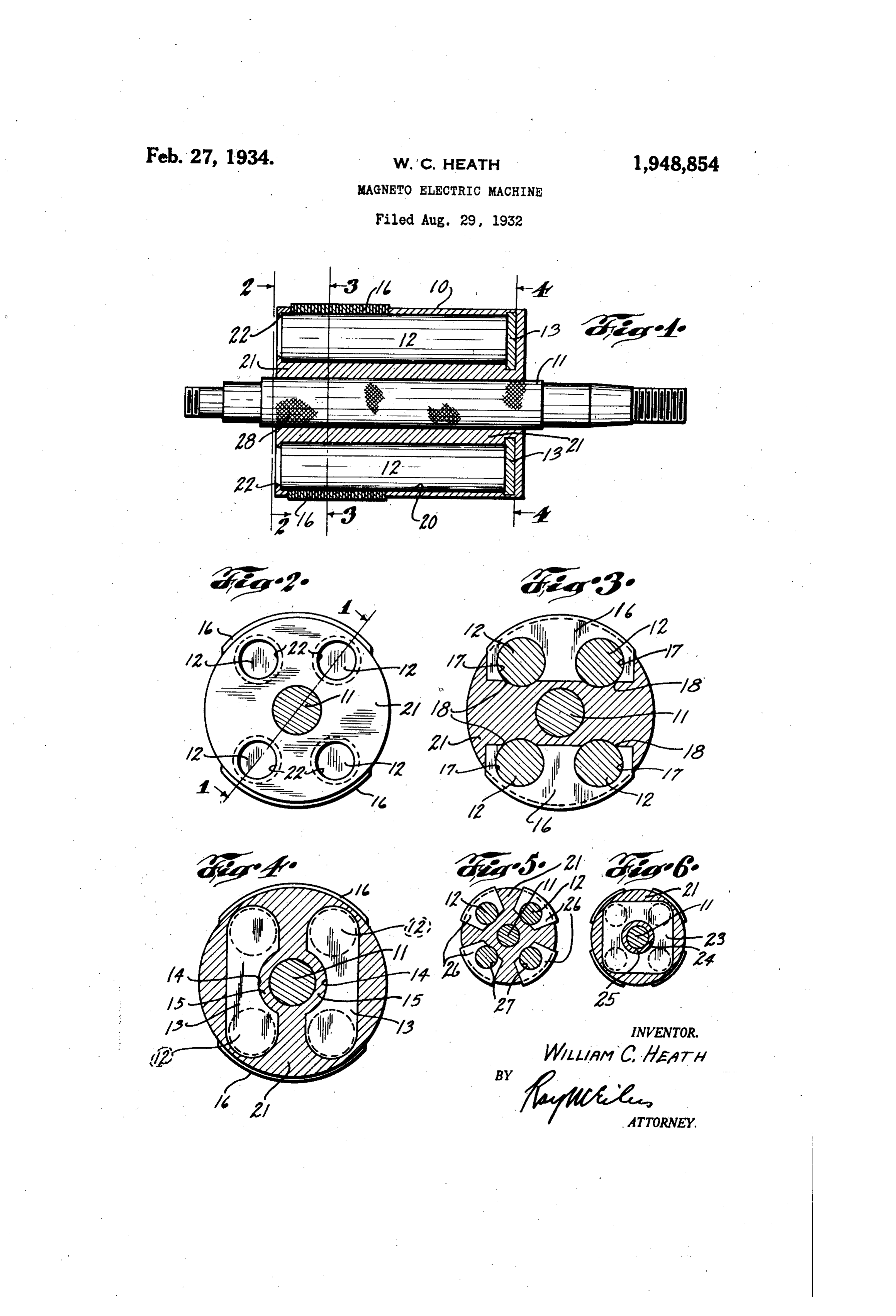
In certain prior types of magnet rotors, it is Further objects and advantages will appear usual to employ a mass of cast non-magnetic, from the following detailed description of parts, metal, such as brass, for the rotor shaft and for and the accompanying drawing of a single pre intimately uniting the laminated - pole shoes. ferred embodiment, and in which: . Such structures are not desirable, in that a shaft Fig. 1 is a longitudinal section of a preferred O of such metal is usually lacking in the requisite form of rotor for magnetos of the rotating field rigidity, and is needlessly expensive for shafting type, the Section being taken along line 1-1 of
Fig. 2; Fig. 2 is an end elevation, partially in sec material. In magnetos of this type it is desir tion, able to employ permanent magnets formed of as viewed from line 2-2 in Fig. 1; Fig. 3 is a cobalt steel or other material having high mag Section taken along line 3-3 in Fig. 1; Fig. 4 is a netic retentivity. Such materials have not been section taken along line 4-4 in Fig. 1; Fig. 5 is a TO widely used in magnetos because of the difficulty Section, substantially reduced in size, taken along experienced in machining the pole pieces and in line 3-3 in Fig. 1, and showing a modified pole securing them to the rotor. In prior types of shoe construction; and Fig. 6 is a reduced section rotor constructions it is not an uncommon prac taken along line 4-4 in Fig. 1 and showing a tice to employ screws or other like fastening modified form of magnet bridging member to be S means for Securing the permanent magnets and employed in connection with the pole shoe con the various other parts to the rotor shaft, . Such struction shown in Fig. 5.
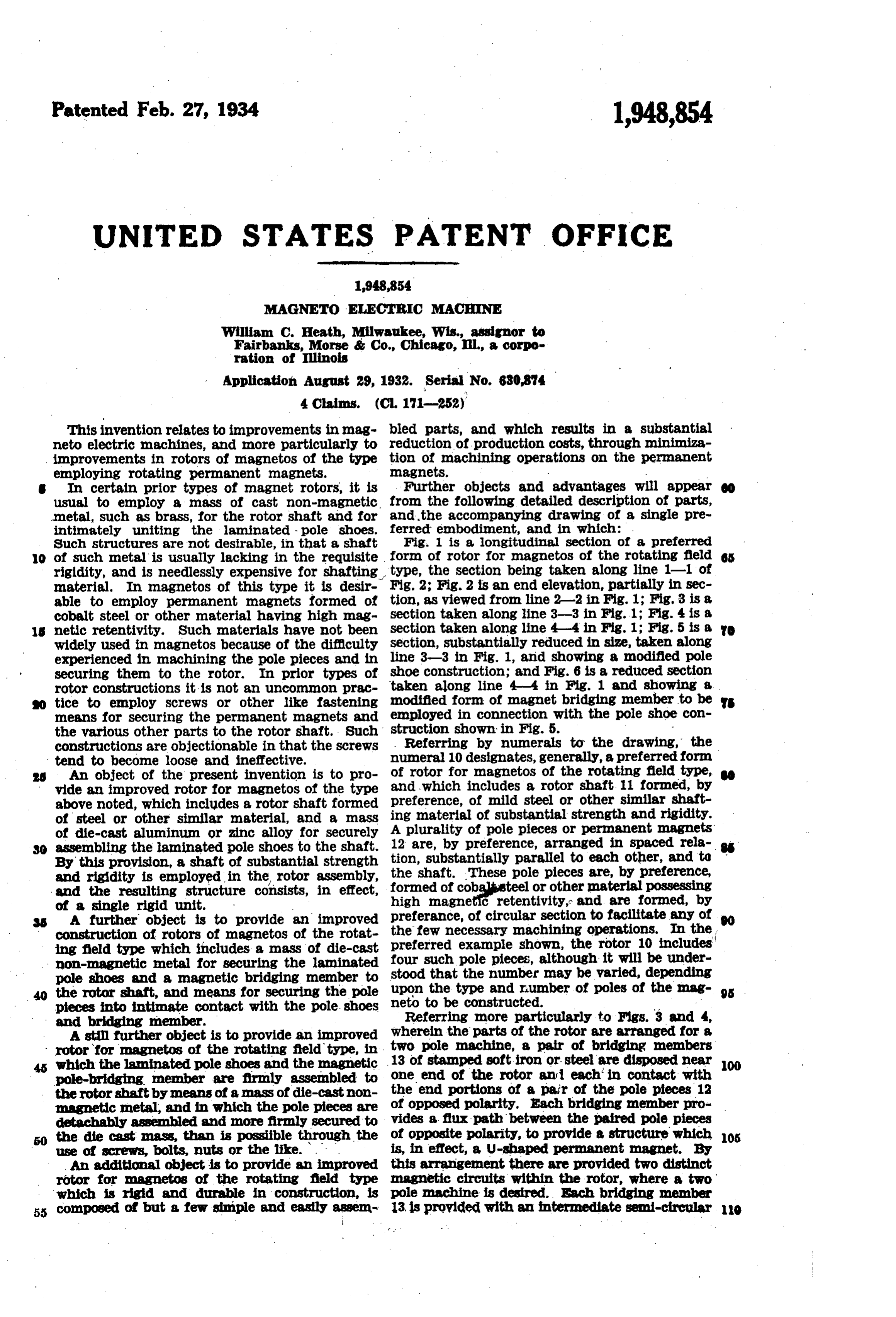
constructions are objectionable in that the screws . Referring by numerals to the drawing, the tend to become loose and ineffective. numeral 10 designates, generally, a preferred form An object of the present invention is to pro of rotor for magnetos of the rotating field type, vide an improved rotor for magnetos of the type and which includes a rotor shaft. 11 formed, by above noted, which includes a rotor shaft formed preference, of mild steel or other similar shaft of steel or other similar material, and a mass ing material of substantial strength and rigidity. of die-cast aluminum or zinc alloy for securely A plurality of pole pieces or permanent magnets SO assembling the laminated pole shoes to the shaft. 12 are, by preference, arranged in spaced rela By this provision, a shaft of substantial strength tion, substantially parallel to each other, and to the shaft. These pole pieces are, by preference, and rigidity is employed in the rotor assembly, formed of cobalisteel or other material possessing and the resulting structure consists, in effect, high magnetic of a single rigid unit. retentivity, and are formed, by A further object is to provide an improved preferance, of circular section to facilitate any of construction of rotors of magnetos of the rotat the few necessary machining operations. In the preferred example shown, the rotor 10 includes ing field type which includes a mass of die-cast four such pole pieces, although it will be under non-magnetic metal for securing the laminated pole shoes and a magnetic bridging member to stood that the number may be varied, depending the rotor shaft, and means for securing the pole upon the type and number of poles of the mag pieces into intimate contact with the pole shoes neto to be constructed.
and bridging member. Referring more particularly to Figs. 3 and 4, A still further object is to provide an improved wherein the parts of the rotor are arranged for a rotor for magnetos of the rotating field type, in . two pole machine, a pair of bridging members which the laminated pole shoes and the magnetic 13 of stamped soft iron or steel are disposed near 00 pole-bridging member are firmly assembled to one end of the rotor and each in contact with the rotor shaft by means of a mass of die-cast non the end portions of a pair of the pole pieces 12 magnetic metal, and in which the pole pieces are of opposed polarity. Each bridging member pro detachably assembled and more firmly secured to vides a flux path between the paired pole pieces the die cast mass than is possible through the is, of opposite polarity, to provide a structure which 05 useAnofadditional screws, bolts, nuts or the like. . . . in effect, a U-shaped permanent magnet. By object is to provide an improved this arrangement there are provided two distinct rotor for magnetos of the rotating field type magnetic circuits within the rotor, where a two which is rigid and durable in construction, is pole machine is desired. Sach bridging member 55 composed of but a few simple and easily assen 13, is provided with an intermediate semi-circular O
Page 3
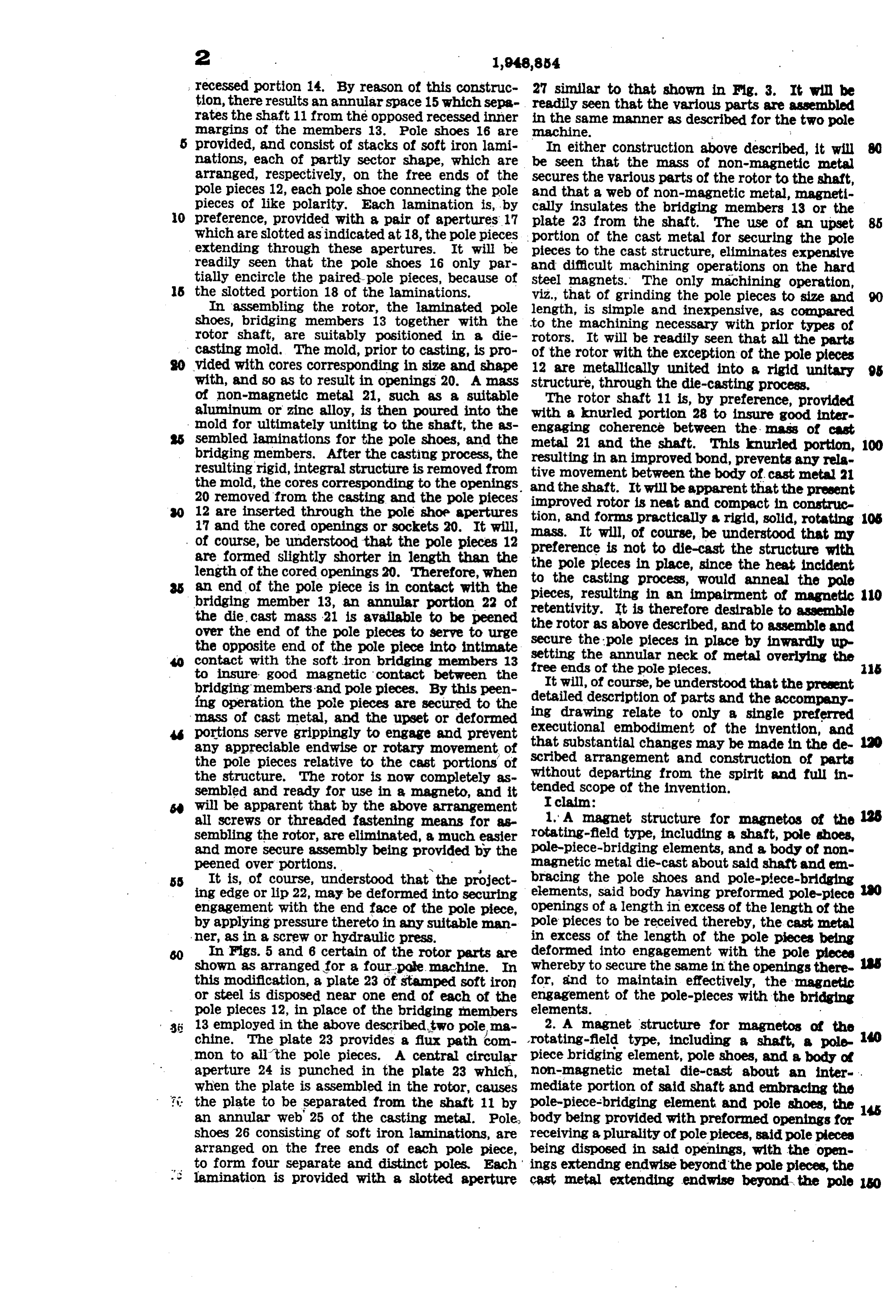
recessed portion 14. By reason of this construc 27 similar to that shown in Fig. 3. It will be tion, there results an annular space 15 which sepa readily seen that the various parts are assembled rates the shaft 11 from the Opposed recessed inner in the same manner as described for the two pole margins of the members 13. Pole shoes 16 are machine.
provided, and consist of stacks of soft iron lami In either construction above described, it will nations, each of partly sector shape, which are be seen that the mass of non-magnetic metal arranged, respectively, on the free ends of the secures the various parts of the rotor to the shaft, pole pieces 12, each pole shoe connecting the pole and that a web of non-magnetic metal, magneti pieces of like polarity. Each lamination is, by cally insulates the bridging members 13 or the 0 preference, provided with a pair of apertures 17 plate 23 from the shaft. The use of an upset which are slotted as indicated at 18, the polepieces portion of the cast metal for securing the pole extending through these apertures. It will be pieces to the cast structure, eliminates expensive readily seen that the pole shoes 16 Only par and difficult machining operations. On the hard tially encircle the paired-pole pieces, because of steel magnets. The only machining operation, s the slotted portion 18 of the laminations. viz., that of grinding the pole pieces to size and In assembling the rotor, the laminated pole length, is simple and inexpensive, as compared shoes, bridging members 13 together with the to the machining necessary with prior types of rotor shaft, are suitably positioned in a die rotors. It will be readily seen that all the parts casting mold. The mold, prior to casting, is pro of the rotor with the exception of the pole pieces vided with cores corresponding in size and shape 12 are metallically united into a rigid unitary 95 with, and so as to result in openings 20. A mass structure, through the die-casting process. of non-magnetic metal 21, such as a suitable The rotor shaft 11 is, by preference, provided aluminum or zinc alloy, is then poured into the with a knurled portion 28 to insure good inter mold for ultimately uniting to the shaft, the as engaging coherence between the mass of cast sembled aminations for the pole shoes, and the metal 21 and the shaft. This knurled portion, 100 bridging members. After the casting process, the resulting in an improved bond, prevents any rela resulting rigid, integral structure is removed from tive movement between the body of cast metal 21 the mold, the cores corresponding to the openings and the shaft. It will be apparent that the present 20 removed from the casting and the pole pieces improved rotor is neat and compact in construc 12 are inserted through the pole shoe apertures tion, and forms 17 and the cored openings or sockets 20. It will, mass. It will, Ofpractically a rigid, solid, rotating 105 of course, be understood that the pole pieces 12 preference is not to die-castunderstood course, be the that my structure with are formed slightly shorter in length than the the pole pieces in place, since the heat incident length of the cored openings 20. Therefore, when to the casting process, would anneal the pole an end of the pole piece is in contact with the bridging member 13, an annular portion 22 of pieces, resulting in an impairment of magnetic 110 retentivity. It is therefore desirable to assemble the die cast mass 21 is available to be peened the rotor as above described, and to assemble and over the end of the pole pieces to serve to urge Secure the pole pieces in place by inwardly up the opposite end of the pole piece into intimate setting the annular neck of metal overlying the contact with the soft iron bridging members 13 to insure good magnetic contact between the free ends of the pole pieces. 15 It will, of course, be understood that the present bridging members and pole pieces. By this peen detailed description of parts and the accompany fing operation the pole pieces are secured to the ing drawing relate to only a single preferred mass of cast metal, and the upset or deformed executional embodiment portions serve grippingly to engage and prevent that substantial changes may of the invention, and any appreciable endwise or rotary movement of scribed arrangement and constructionbe made in the de-120 the pole pieces relative to the cast portions of of parts the structure. The rotor is now completely as without departing from the spirit and full in sembled and ready for use in a magneto, and it tended scope of the invention.
will be apparent that by the above arrangement I claim: f all screws or threaded fastening means for as 1. A magnet structure for magnetos of the sembling the rotor, are eliminated, a much easier rotating-field type, including a shaft, pole shoes, and more secure assembly being provided by the pole-piece-bridging elements, and a body of non peened over portions. - magnetic metal die-cast about said shaft and en SS It is, of course, understood that the project bracing the pole shoes and pole-piece-bridging ing edge or lip 22, may be deformed into securing elements, said body having preformed pole-piece O engagement with the end face of the pole piece, openings of a length in excess of the length of the by applying pressure thereto in any suitable man pole pieces to be received thereby, the cast metal ner, as in a screw or hydraulic press. in excess of the length of the pole pieces being In Figs. 5 and 6 certain of the rotor parts are deformed into engagement with the pole pieces shown as arranged for a four-pole. machine. In whereby to secure the same in the openings there this modification, a plate 23 of stamped soft iron for, and to maintain effectively, the magnetic or steel is disposed near One end of each of the engagement of the pole-pieces with the bridging pole pieces 12, in place of the bridging members elements. .
13 employed in the above described two polema 2. A magnet structure for magnetos of the chine. The plate 23 provides a flux path com rotating-field type, including a shaft, a pole mon to all the pole pieces. A central circular piece bridging element, pole shoes, and a body of aperture 24 is punched in the plate 23 which, non-magnetic metal die-cast about an inter- . when the plate is assembled in the rotor, causes mediate portion of said shaft and embracing the the plate to be separated from the shaft 11 by pole-piece-bridging element and pole shoes, the 145 an annular web 25 of the casting metal. Pole. body being provided with preformed Openings for shoes 26 consisting of soft iron laminations, are receiving a plurality of pole pieces, said pole pieces arranged on the free ends of each pole piece, being disposed in said openings, with the open to form four separate and distinct poles. Each ings extending endwise beyond the pole pieces, the lamination is provided with a slotted aperture cast metal extending endwise beyond the pole O
Page 4
pieces being deformed into engagement with cor 4. The herein described method of assembling responding ends of the pole pieces. a plurality of pole pieces in a die-cast body of a 3. A magnet structure for magnetos of the magneto rotor structure of the rotating field type, rotating field type, including a die-cast body of which consists in die-casting a body of non-mag non-magnetic metal provided with cast-in pole netic metal about a pole-piece bridging member, shoes, pole-piece bridging elements and a shaft in preforming sockets in the die-cast metal body, of ferrous metal, the body being constructed with of a length in excess of the pole pieces; in inserting preformed pole piece sockets, the inner, ends of said pole pieces in said sockets, so that portions which are terminated by said bridging elements, of the cast body extend beyond the pole pieces, O and the opposite ends of which extend outwardly when in assembled relation; and in deforming beyond the pole pieces when inserted therein, the the metal lying outwardly of the pole pieces and metal about said projecting outer ends being de adjacent said sockets, whereby to secure the pole formed into holding engagement with the pole pieces in assembled relation in the cast body and pieces, and adapted thereby to keep the pole to maintain the pole pieces in effective magnetic s pieces in magnetic relation with said bridging engagement with the bridging member. 00 elements. WAM. C. B.A. H.
Provenance
- Collection
- Cited prior art
- Original PDF
- patentimages.storage.googleapis.com →
- Filed
- 1932-08-29
- Pages
- 4
- Method
- pdftotext (the PDF's own text layer) + pdftoppm 300dpi page scans
- Source
- Google Patents bibliographic record
- Granted
- 1934-02-27
- Inventors
- William C Heath; Fairbanks Morse and Co
- Transcribed from
- patentimages.storage.googleapis.com →