patent · US5811908
Magneto electric generator rotor and an implement for removing this rotor
22 September 1998
Page 1 — bibliographic record
United States Patent (19) 11 Patent Number: 5,811,908 Iwata et al. (45) Date of Patent: Sep. 22, 1998
54) MAGNETO ELECTRIC GENERATOR 4,571,528 2/1986 McGee et al. .......................... 318/138 ROTOR AND AN IMPLEMENT FOR 4,769,624 9/1988 Merritt et al. .......................... 335/302 REMOVING THIS ROTOR 4,973,871 11/1990 Bisantz .................................... 310/154 4,980,592 12/1990 Olmr et al. . 310/153
O O 4,980,593 12/1990 Edmundson ............................ 310/154 75 Inventors: R", R.N.A.Kal 5,118,978 6/1992 Matsumoto et al. .................... 310/153 , YOKOnama, s 5,216,306 6/1993 Nakazawa et al. ....................... 310/89 Sayama, all of Japan 5,399,929 3/1995 Okada et al. ........................... 310/154 73 Assignee: Oppama Industry Co. Ltd.,
Kanagawa-ken, Japan Primary Examiner-Steven L. Stephan
Assistant Examiner Timothy A. Williams
Attorney, Agent, or Firm Michael D. Bednarek; Kilpatrick 21 Appl. No.: 641,647 Stockton LLP 22 Filed: May 1, 1996 57 ABSTRACT 30 Foreign Application Priority Data
By inserting a male Screw for fixing a ratchet claw into a nut
May 2, 1995 |JP Japan .................................... 7-132689 placed on an insert core and the like to prevent rotation, it May 2, 1995 JP Japan ... is possible to eliminate additional Screw processing on the Jul. 5, 1995 JP Japan .... insert core, to increase magnetic resistance between a mag Jul. 20, 1995 JP Japan .... net and the insert core provided with the former, to concen Jul.27, 1995 Pi Japan . 7210977 trate irradiation of magnetic flux from the Second magnet (51) Int. Cl. ................................................. HO2K 1/22 pole toward outside and to fix the magnet and the Second 52 U.S. Cl. ........................... 310/261; 310/154; 310/156 magnet pole onto the insert core with Screws. Further, by 58 Field of Search ..................................... 310/156, 154, tapering an axial hole of the rotor, it is possible to easily and 310/261 accurately attach the insert core or the rotor to a crankshaft.
Furthermore, by inserting a removal parts of a removal tool 56) References Cited into a perforation hole of the rotor, it is possible to realize
quick and Simple removal of the rotor from the crankshaft.
4,491,769 1/1985 Heidelberg .............................. 3.18/254 11 Claims, 20 Drawing Sheets
Page 2
Drawing sheet — no readable text.
Page 3
Drawing sheet — no readable text.
Page 4
Drawing sheet — no readable text.
Page 5
Drawing sheet — no readable text.
Page 6
Drawing sheet — no readable text.
Page 7
Drawing sheet — no readable text.
Page 8
Drawing sheet — no readable text.
Page 9
Drawing sheet — no readable text.
Page 10
Drawing sheet — no readable text.
Page 11
Drawing sheet — no readable text.
Page 12
Drawing sheet — no readable text.
Page 13
Drawing sheet — no readable text.
Page 14
Drawing sheet — no readable text.
Page 15
Drawing sheet — no readable text.
Page 16
Drawing sheet — no readable text.
Page 17
Drawing sheet — no readable text.
Page 18
Drawing sheet — no readable text.
Page 19
Drawing sheet — no readable text.
Page 20
Drawing sheet — no readable text.
Page 21
Drawing sheet — no readable text.
Page 22
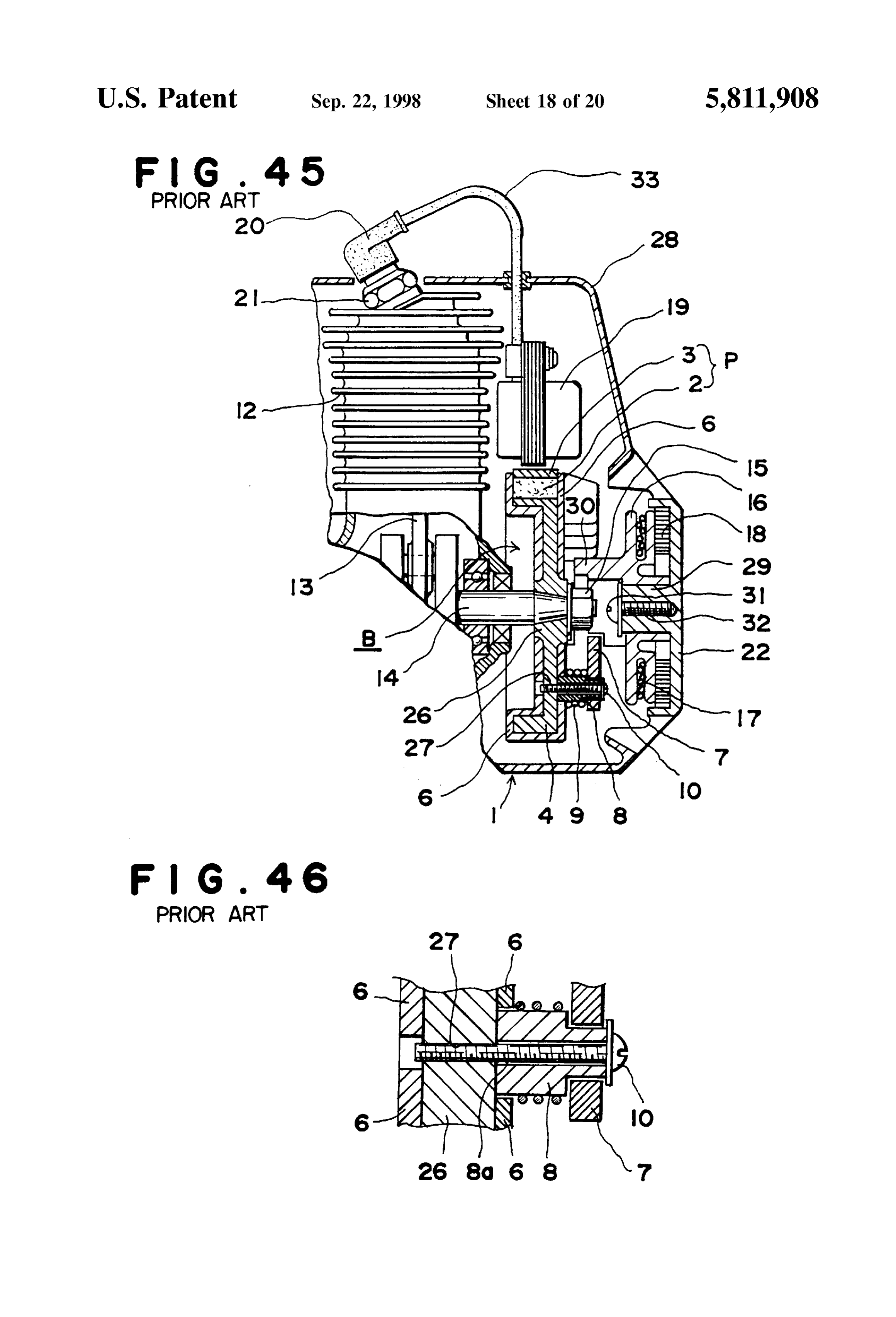
MAGNETO ELECTRIC GENERATOR 16 catches on the ratchet claw 7 on rotor B which has a ROTOR AND AN IMPLEMENT FOR magnet 2 buried in the insert core 26, and rotates rotor B. REMOVING THIS ROTOR In this way, because Said rotor B is attached to the crankshaft 14 of the engine 1, the crankshaft 14 is driven to
BACKGROUND OF THE INVENTION rotate by Said rotor B and the engine 1 is cranked up. 1. Field of the Invention On one hand, at that time the magnetic flux of the magnet This invention relates to a magneto electric generator 2having attached to said rotor B interlinks with the coil unit 19 an ignition control circuit fixed to the cylinder 12 rotor used in an internal combustion engine Spark plug and an implement for removing this rotor. 1O side of said engine 1. Said coil unit 16 will thus generate a power output and this power output will be Supplied to the 2. Explanation of Prior Art ignition plug 2 through the cable 3 q and the plug cap 20, and FIGS. 45 and 46 show a broken down section of a small by this, the ignition plug 21 will generate a Spark, ignite the Size engine used in a conventional operating machine In Said gas mixture in the cylinder 12, and Start up the engine 1. figures numeral I is a Small size engine, 1 is a cylinder for Further, the fixing of the ratchet claw 7 described previ Said engine 1, and 13 is a connecting rod Supporting a piston 15 ously is done by Screwing in the axle part 8 Supporting it in that moves in this cylinder 12 Also, 14 is a crankshaft for a ratable manner to the insert core 26 of the male Screw 10. eccentric driving the end of said con rod 13, and 15 is a nut For this reason the female screw 27 conforming to the male to fix rotor Battached to the end of this crankshaft 14. Screw 10 is machine tooled as aforementioned in the said One side of said rotor B that is on the opposite side of an rotor B.
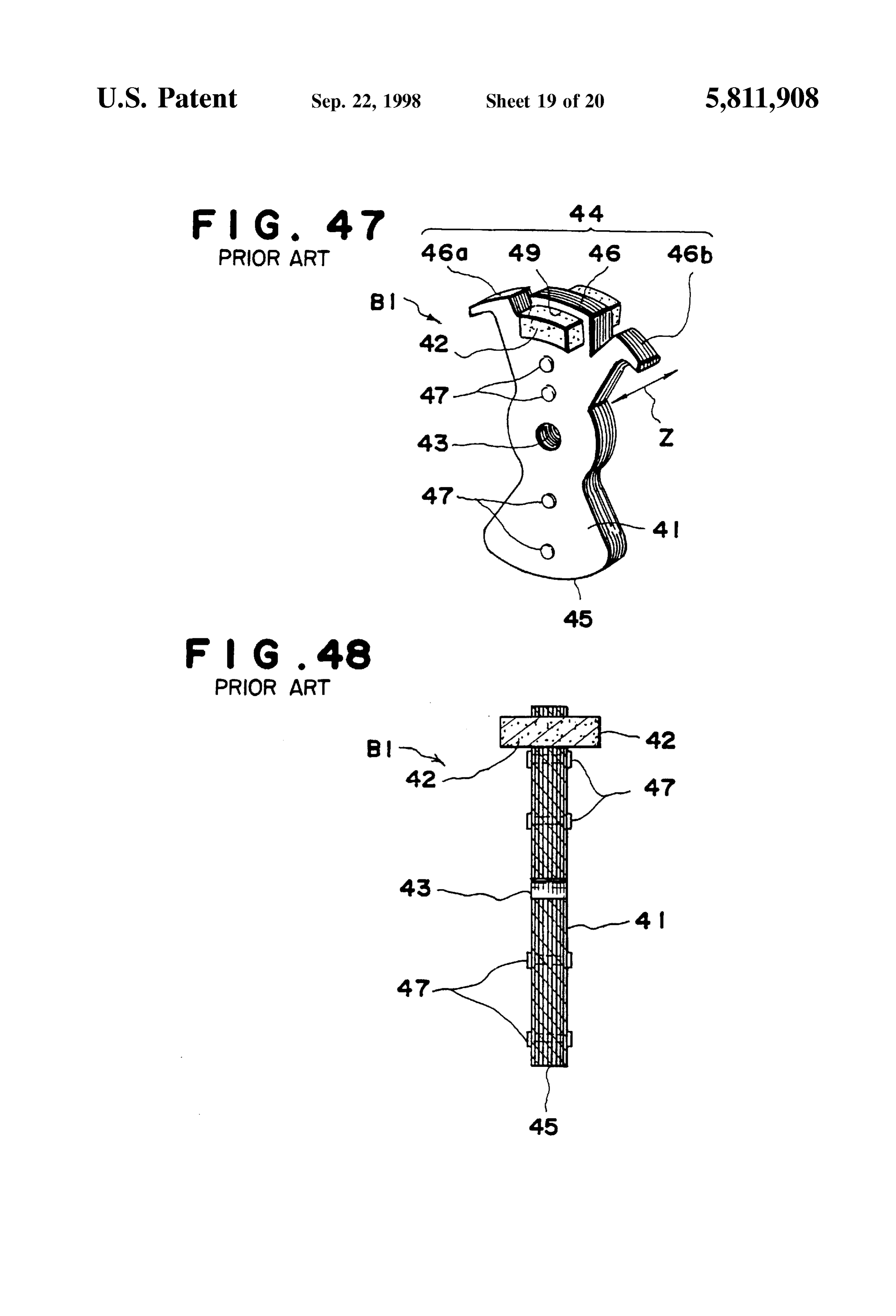
axial hole part through which the crankshaft 14 is inserted On one hand, the rotor shown in FIGS. 47 and 48 has been through Secures a magnet 2 and forms a pole piece part P proposed in the past as a rotor used in a magnetic power together with a magnetic pole 3, while the other Side is generating machine Such as the one described above. This composed of an insert core 26 of a ferromagnetic material rotor B I is a rotor having a hole piece part 44 with a magnet that becomes counter weight part 4. Further, a cooling fan 25 42 on one Side and an insert core 41 as a counter weight part and the like is installed to this insert core 26 to form one body. 45 on the opposite side of an axial hole part 43 buried as an insert form within a synthetic resin (not shown). This rotor
Numeral 6 is a non-magnetic material layer Such as a B1 is described in, for example Japanese Utility Model Synthetic resin layer formed in a discoidal shape So as to Publication 1993-10526.
cover Said insert core 26.
In this conventional rotor B I, the insert core 41 has been
On one hand 7 is a ratchet claw which is supported in a made into an integrated unit with a rivet 47 riveting together freely revolving manner to an axle part 8 having a hole 8a layers of multiple magnetic plates in multiple locations, and as a cylinder part. Also, as shown in FIG. 46, a male Screw said axial hole part 43 is a straight hole with the diameter 10 is inserted through this axle part 8, and the tip of this male being equal in the direction of the axle. Screw 10 is screwed into and fixed to female Screw 27 which 35 Also, of the 3 magnetic poles, 46, 46a and 46b forming has been formed beforehand in said insert core 26. the pole piece 44, Said magnet 42 is inserted in an open hole Numeral 9 is a ratchet spring of which one end is fixed to 49 formed in the center magnetic pole 46, and both ends of Said axle part S, and the other end is fixed to Said ratchet the magnet protrude outward towards the axial fringe of claw 7 and this gives a rotating force in one direction to the each magnet pole 46, 46a and 46b.
ratchet claw 7. 40
In Such insert core 41, the pole piece part 44 and the
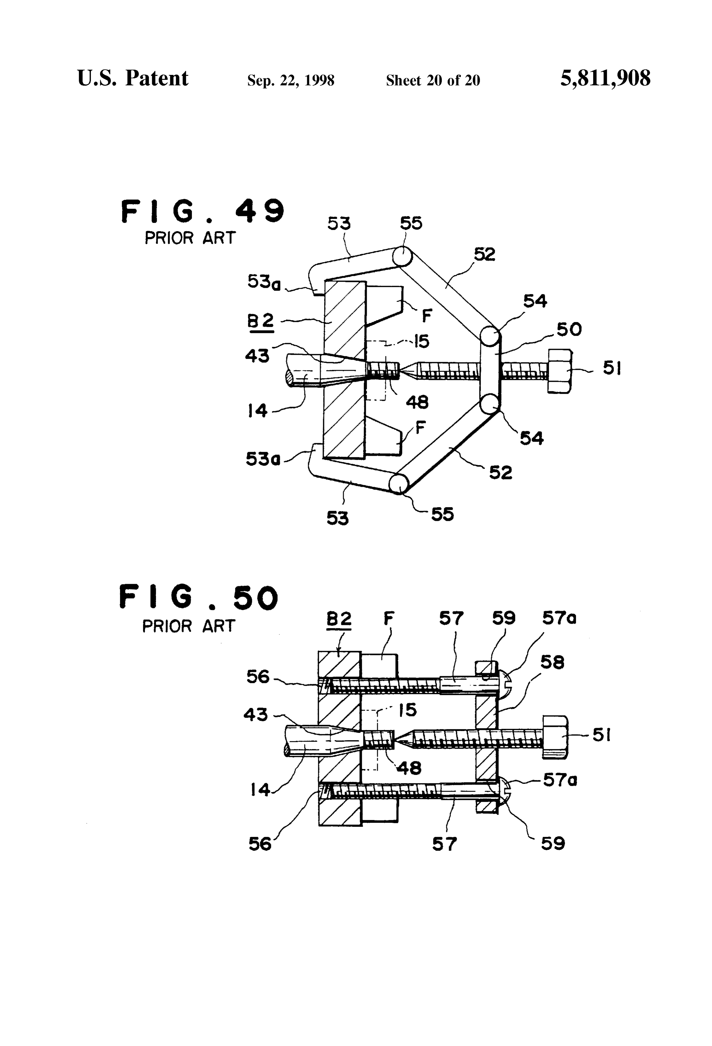
Also, a reel axle 29 is provided in one body so as to counter weight part 45 are formed in one body, and because project into an operating machine frame 28 opposite to Said there is no need for assembly work and machine tooling after rotor B. A reel 16 having continuously wound thereon a rope die casting the advantage of a relatively low cost is achieved. 17 is supported on this reel axle 29 in a freely rotating On one hand, in the past, when removing the rotor of a manner. On to this reel 16 provided with an engagement part 45 magnetic power generator from the crankshaft 14 of an 30 which catches said ratchet claw 7 and gives a rotating engine Such as shown in FIG. 45, a pulley removing tool is force to the reel 16. used to remove the pulley attached to the rotary axle. Aspiral Spring 18 is installed in the periphery of Said reel FIG. 49 shows such a conventional pulley removing tool axle 29 to apply to said reel 16 a rotating force around this 50 and a rotor B2 of a magnetic power generator removed reel axle 29.31 is a washer fixed to the end of the reel axle there with. In Said drawing, 14 is the engine crankshaft, and 29 by a screw 32 and serves as a protector to prevent the axle this crankshaft 14 is provided with an axial hole 43 for rotor hole of the reel 16 from coming off of the reel axle 29. B2 having a magnet and counter weight and the like, and Moreover, the reel axle 29, the reel 16, the rope 17, the spiral made in a virtually circular form with a non-magnetic spring 18. The engagement part 30, the ratchet claw 7 and 55 material.
the like form a recoil starter. Also, said rotor B2 is fixed to the crankshaft 14, So as not Also, 19 is a coil unit formed a power generating coil, to come off freely, with a nut 15 screwed on a male screw ignition coil, ignition control circuit and the like in one body part 48 formed on the crankshaft 14 end Moreover, F is a with thermosetting or thermoplastic Synthetic resin and is multiple bladed cooling fan installed along the circuit direc fixed to said cylinder 12 side. 60 tion of one side of the rotor B2. 20 is a plug cap connected to Said coil unit 19 through a On one hand 50 is a bolt attachment part on which a bolt cable 33. This plug cap 90 is connected to a plug 21 next to 51 is screwed on at the center part and to both ends are the cylinder 12. 28 is the operating machine frame housing connected arms 52 and 53 through axle supports 54 and 55, an engine. and a disengagement claw 53a is installed on the tip of the In a Small size engine made of Such a construction, the 65 arm 53.
reel 16 rotates by manually pulling the rope 17 wound on With this pulley removing tool, first the disengagement this reel 16, and the engagement part 30 installed on Said reel claw 53a of each of said arm 53 ends is disengaged at the
Page 23
inner Surface of the outer circuit part of the rotor B2 that is pole 46 and will not reach the power generating coil and pressed against the crankshaft 14 and the tip of said bolt 15 ignition coil. For this reason, the power generating capacity is pressed against the tip of the crankshaft 14. for ignition and the like cannot be Sufficiently generated. Further, the nut 15 is removed from the male screw part Also, when using a layered insert core 41 in an attempt to 48 before and after such operation, then said bolt 51 is Sufficiently bring out the capacity of Said magnet 42, it will screwed on the attachment part 50. With this, the arms 52 be necessary to increase the thickness of the layers which and 53 will be subjected to an axial directed torque due to results in increase of weight of whole rotor. Also, in case the the Screwing on power and change the position of the layered cost thickneSS is altered partially, the increase of initial accompanying the increased cost for press molds and supporting axles 54 and 55 to the center, and the rotor B2, which was being held by the disengaging claw 53a, is theFurther, increase in the proceSS StepS and costs cannot be avoided. it has been proposed that an insert core 41 be removed in the axial direction from the crankshaft 14.
formed with a magnetic Sintered alloy and Said magnet
FIG. 50 shows a conventional rotor removal tool and a introduced between the insert core 41 and the magnetic pole rotor B2 of a magnetic power generator that is removed with on the Support provided thereon. However, in this case it will said tool. In the drawing 56 is multiple screw holes provided 15 be necessary to make the Support fairly thick due to the on the rotor B2SO as to pass through both Sides of Said rotor. conditions for forming.
Also, 57 is a male Screw, whose tip can be Screwed into For this reason, this Support will invite Shortages in the the screw hole 56. Said male Screw 57 is screwed into a magnetic circuit and the magnetic flux generation rate in through hold 59 provided in a plate 58 and the male screw Said magnetic pole will deteriorate, and the power generat 57 is prevented from pass in through by a screw head 57a. ing capacity in Said power generating coil and the like will On to said plate 58, a bolt 51 is screwed into its center part also become inadequate.
and it is possible for the tip of the bolt to hit the tip of said Further, in the removal method for rotor B2 shown in FIG. crankshaft 14. 49, it will be necessary to disengage the disengaging claw 53 along the outer Surface of the rotor B2. At present, when
According to this removal tool, the tip of the male Screw miniaturization 57 is screwed into said screw hole 56 in certain depth then is being aimed at,ofittheis difficult 25 magnetic power generator and engine said bolt 51 is screwed into the plate 58 until the tip of the Such a disengagement claw 53 to keep the Space required for on the peripheral of Said rotor bolt 51 hits the end of the crankshaft 14.
B2 and as a result Such a pulley removal tool cannot be
Then, while keeping said plate 58 in a position that is practically used.
parallel to the rotor B2, said bolt 51 is screwed in. By doing this, the power to remove the rotor B2 from the crankshaft necessary tothe
Also, in removal method shown in FIG. 50, it is apply an additional process of a Screw hole 3 S 14 is provided to the rotor through the male screw 57 in the for the rotor obtained by molding to the latter steps of plate 58. For this reason the rotor B2 can be smoothly processing, and the non-processing of the rotor B2 cannot be removed from the crankshaft 14.
realized which will invite a decrease in production efficiency
However, with a rotor B of a conventional magnetic and an increase in cost power generator such as that shown in FIGS. 45 and 46, 35 SUMMARY OF THE INVENTION even at present when the nonprocessing of the rotor B has become advanced, but only the processing of the Screw The present invention was made based on Said Situation, (female screw) 27, which is used for fixing said ratchet claw and the object is to provide an inexpensive magnetic power 7 cannot be eliminated For this reason a reduction in cost
generator rotor on which a claw can be easily and reliably could not be achieved. attached without any Special workmanship nor Screw pro Also, with a rotor using an insert core of layered magnetic cessing.
plates and formed into an approximately circular shape with Also, this invention has the object of enabling an adequate plastic, the processing of Said Screw for use in attaching the concentration of Said magnetic flux of a magnet to the ratchet could not be carried out without performing Special 45 magnetic pole by increasing the magnetic resistance of the work Such as inserting aluminum parts. magnetic circuit connecting the magnetic pole to the insert Also, because the axial hole part 43 is a Straight hole in core, thereby obtaining a magnetic power generator rotor the rotor B I of the conventional magnetic power generator that can improve the power generating capacity in the power shown in FIGS. 47 and 48, when assembling said axial hole generating coil and the like.
part 43 to the crankshaft 14 of the internal combustion 50 Also, this invention has the object of obtaining a magnetic engine, it is difficult to provide Sufficient cohesive Strength power generator rotor that can more adequately concentrate to both parts. Also, in order to provide Sufficient cohesive the magnetic flux of a magnet on a Specific magnetic pole. Strength to both parts, it is necessary to use a separately Also, this invention has the object of obtaining a magnetic prepared cohesion aid tool. power generator rotor that can fix the magnet and magnetic Also, in order to provide Sufficient cohesion Strength to 55 pole to the insert core reliably and inexpensively without Said axial hole part 43 and Said rotor B I, Said axial hole part Subjecting the insert core to any machine tooling at all. 43 can be made into a tapered hole and tighten the bond Also, this invention has the object of obtaining a magnetic between both parts. However, in said layered insert core 41, power generator rotor that can reliably prevent a magnet the tapered hole will be terraced with each layer of the plate. from shifting out of place on the target Surface when For this reason the contact with said crankshaft 14 will 60 assembling on an insert core.
become shaky and the cohesion between both parts will be Also, this invention has the object of obtaining a magnetic imperfect. power generator rotor that enables the easy implementation Further, because both ends of the magnet 42 protruded out of the operation for tightly fastening with a Screw and nut a (out of the thickness) in the axial fringe direction Z of each magnet and magnetic pole to an insert core. magnetic pole 46, the magnetic flux of Said magnet 42 could 65 Also, this invention has the object of obtaining a magnetic not be Sufficiently concentrated on magnetic pole 46. That is power generator that enables the easy installation and fixture a part of the magnetic flux would leak outside the magnetic of an insert core of Sintered alloy to a crankshaft.
Page 24
S 6
Also, this invention has the object of obtaining a magnetic position to the axial and circular directions of the rotor and power generator rotor that can reliably implement a stop fixing the magnet in its proper position between first two page of the rotation of a axial hole part on a crankshaft. magnetic poles by providing shift-protecting ribs on the This invention has the object of obtaining a magnetic target Surface of the insert core magnet So as to cover at least power generator rotor that enables removal from a crank the 3 sides of the bottom end of the magnet. shaft very easily and reliably with a removal tool, without Also, the magnetic power generator rotor of this invention Subjecting to an additional process Such as providing a Screw Simplifies the Screwing in operation required for the Screws hole or the like. and nuts by making the indented hole part for the nuts the Also, this invention has the object of obtaining a magnetic shape and Size of the rotation block for the nut and Screwing power generator rotor removal tool that enables the removal said Screw into the nut from the outside of the second of a rotor from a crankshaft in a simple operation and magnetic pole.
manipulation, even without having Sufficient work Space in Also, the magnetic power generator rotor of this invention the periphery of the rotor. makes it possible to utilize their shapes and structure capable Also this invention has the object of obtaining a magnetic 15 of reducing the mass by molding the insert core with a power generator rotor removal tool that enables the removal Sintered magnetic alloy, to maximize the concentration of of a rotor from a crankshaft with a simple disengaging the magnetic flux of the magnet at the magnetic poles by operation for a removal perforation of a removal part. equalizing the length of the axial fringe direction of the To achieve aforementioned objects, in the magnetic magnet and the magnetic poles, and to ensure a firm contact power generator rotor of this invention, a nut rotation of the axial hole part with the crankshaft by making the axial blocking hole and an insert hole for Said male Screw are hole part a tapered hole.
provided on a part of the insert core to which a rotation thisAlso, in the magnetic power generator rotor according to invention, the forming of the key groove against the ratchet claw is fixed, thereby there is no need for a Screw thread processing on this insert core itself latter, and Said axial hole part can be simplified because the insert core can ratchet claw can be fixed to the insert core through an axial 25 be obtained by molding of the sintered alloy, and therefore part Supporting in freely rotating manner Said ratchet claw using this key groove has made it possible to reliably block the rotation of the rotor having Said insert core against the by merely fastening Said nut to Said rotation blocking hole crankshaft.
and Screwing the tip of the male Screw, which had been passed through Said perforation. Also, in the magnetic power generator rotor according to In addition, by forming the axial part Supporting Said this invention, the forming of the key protuberant for the ratchet claw in a manner enabling rotation in one body with be axial hole part can be simplified because the insert core can molded with the Sintered alloy, and using this key
Said insert core during the formation of Said insert core, it is protuberant not necessary to use a cylindrical part forming Said axial part has made it possible to reliably block the as a part and therefore lowering of costs can be planned. rotation of the rotor having Said insert core against the
crankshaft.
Also, the magnetic power generator rotor of this invention Also, with the magnetic power generator rotor of this is provided at the pole piece part with a first pair of magnetic invention poles formed in one body on the insert core and a Second pair Simultaneously a Straight hole as the axial hole part can be formed of magnetic pole made from a magnetic plate installed with its inside Surface in a Smooth condition between said first magnetic poles and held the magnet possible to avoid Such the at the time of forming insert core, and it has been made botherSome post processing as Sur between Said insert core, So that the magnetic flux density 40 face grinding of the inside of the axial hole part as done in that is radiated outside through the Second magnetic poles is the prior art.
increased and the concentration of the magnetic field to Such as the power generating coil and the like is made possible. Also, with the magnetic power generator rotor of this Also, the magnetic power generator rotor of this invention invention the extraction part of a removal tool for removing introduces the Second magnetic pole through a non-magnetic 45 the rotary body from the crankshaft is being inserted in the rotor and a multiple of perforations for removal purpose part between the first magnetic poles and a magnet is whose peripheral part is engaged with this extraction part is contained between the Said insert core with the Second magnetic poles, and thus the concentration of the magnetic remove the rotoronfrom being provided the rotor; and therefore it is possible to the crankshaft by insertion of said flux of the electro-magnet at the Second magnet poles is 50 removal tool into the perforations followed by the operation made possible. of the peripheral engagement and further by the extraction Also, the magnetic power generator rotor of this invention operation of the removal tool.
makes possible the concentration of the magnetic flux of a Also, the magnetic power generator rotor removal tool magnet at the Second magnetic poles, that is in a condition according to this invention is provided with a plate posi of being magnetically insulated from the first magnetic 55 tioned opposite poles, by Screwing Said Second magnetic pole on to the insert ing an axial holetoin the the magnetic power generator rotor hav crankshaft of the engine, a Screw part core between the first magnetic poles with a non-magnetic Screwed into the center part of Said plate So as to pass Screw through a magnet. through the plate with the tip part touching the end of Said Also, the magnetic power generator rotor of this invention crankshaft, and a multiple of extraction parts positioned So makes it possible to easily fix Said magnet and Second 60 as to Stop one end part from passing through Said plate; magnet pole to Said insert core by tightening Said Screw from therein an engagement part inserted into a multiple of the outside of the Second magnetic pole, by joining the perforations for removal provided in Said rotor and engaged magnet and the Second magnetic pole to the Screw and nut with the peripheral part of Said perforations is formed at the to be fixed at the indented hole pan of the opening on the side other end of Said extraction part. Therefore, by inserting the of the insert core. 65 end part of Said extraction part into the perforations for Also, the magnetic power generator rotor of this invention removing the rotor and carrying out the rotation operation, makes it possible to prevent the magnet from shifting its the engagement part of the extraction part hitches on to the
Page 25
peripheral of the perforations for removal and further applies FIG. 14 is a Sectional drawing showing a partially broken a direct torque generated by the Screwing-in operation of the down insert core in a magnetic power generator rotor part to the rotor and crankshaft through Said engagement according to another configuration for implementing this part So that the rotor can be removed from the crankshaft. invention.
Also, the magnetic power generator rotor removal tool of FIG. 15 is a front sectional view showing a magnetic this invention is provided at the end of the removal part with power generator rotor according to another configuration for an engagement protuberant that can be engaged in the implementing this invention.
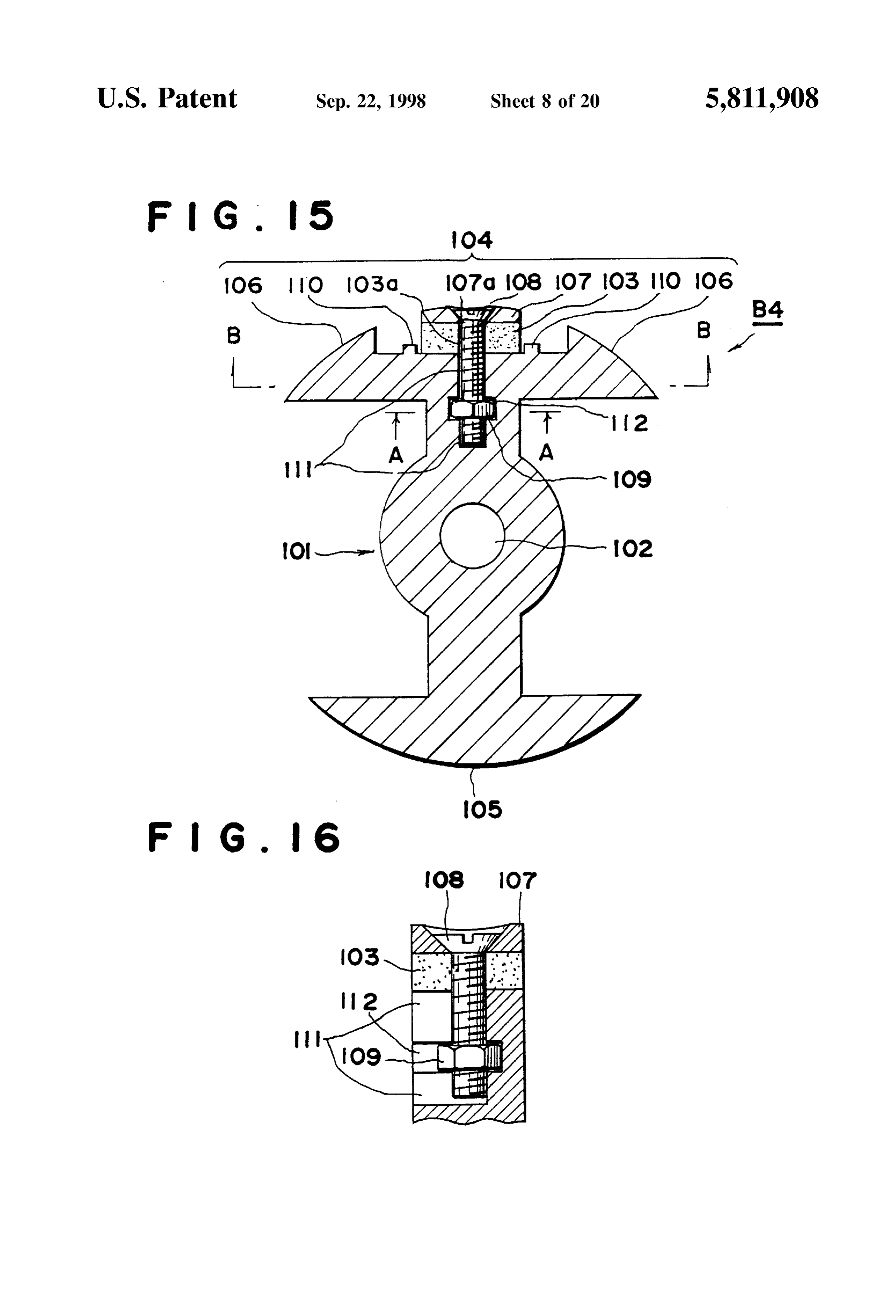
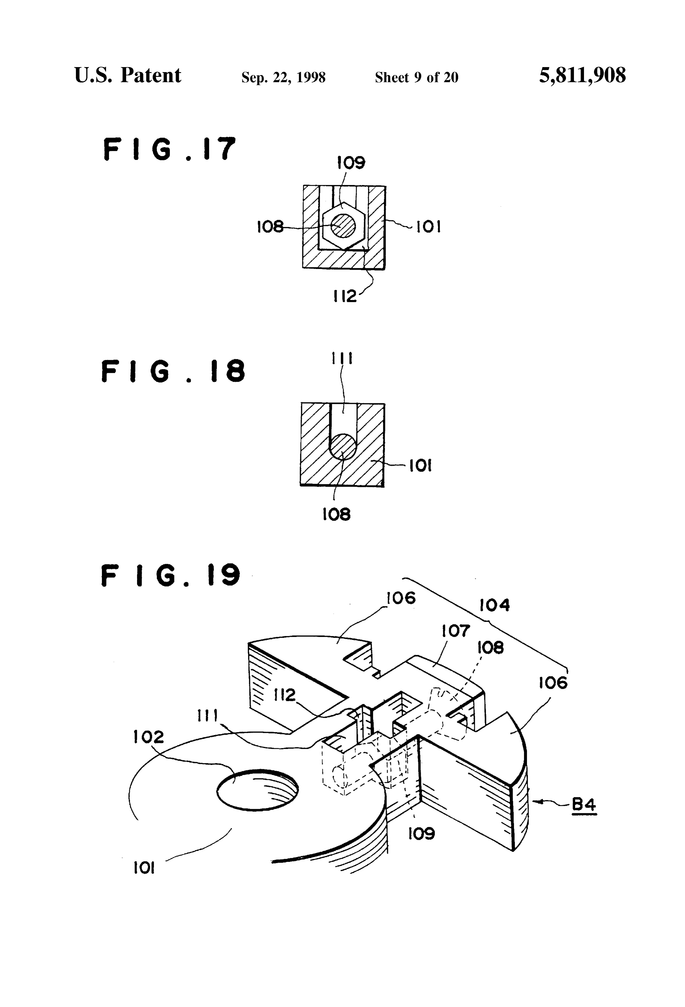
peripheral of the perforations for removing the rotor with the FIG. 16 is a side sectional view showing the partially rotation operation. Therefore, by pulling up said extraction broken down magnetic power generator rotor in FIG. 15 part in this engaged condition by Screwing in the Screw part 1O FIG. 17 is a line A-A sectional view of FIG. 13. through the plate, the extraction of the rotor from the FIG. 18 is a line B-B Sectional view of FIG. 15 crankshaft is made possible.
FIG. 19 is a dismantle view showing the partially broken
Also, the magnetic power generator rotor removal tool of down magnetic this invention is provided with an engagement protuberant 15 power generator rotor in FIG. 15.
part at the tip of the extraction part that can be engaged in broken down magnetic side sectional view showing a partially the area of the perforations for removing the rotor by a linear tion after being ejectionpower generator rotor in this inven formed.
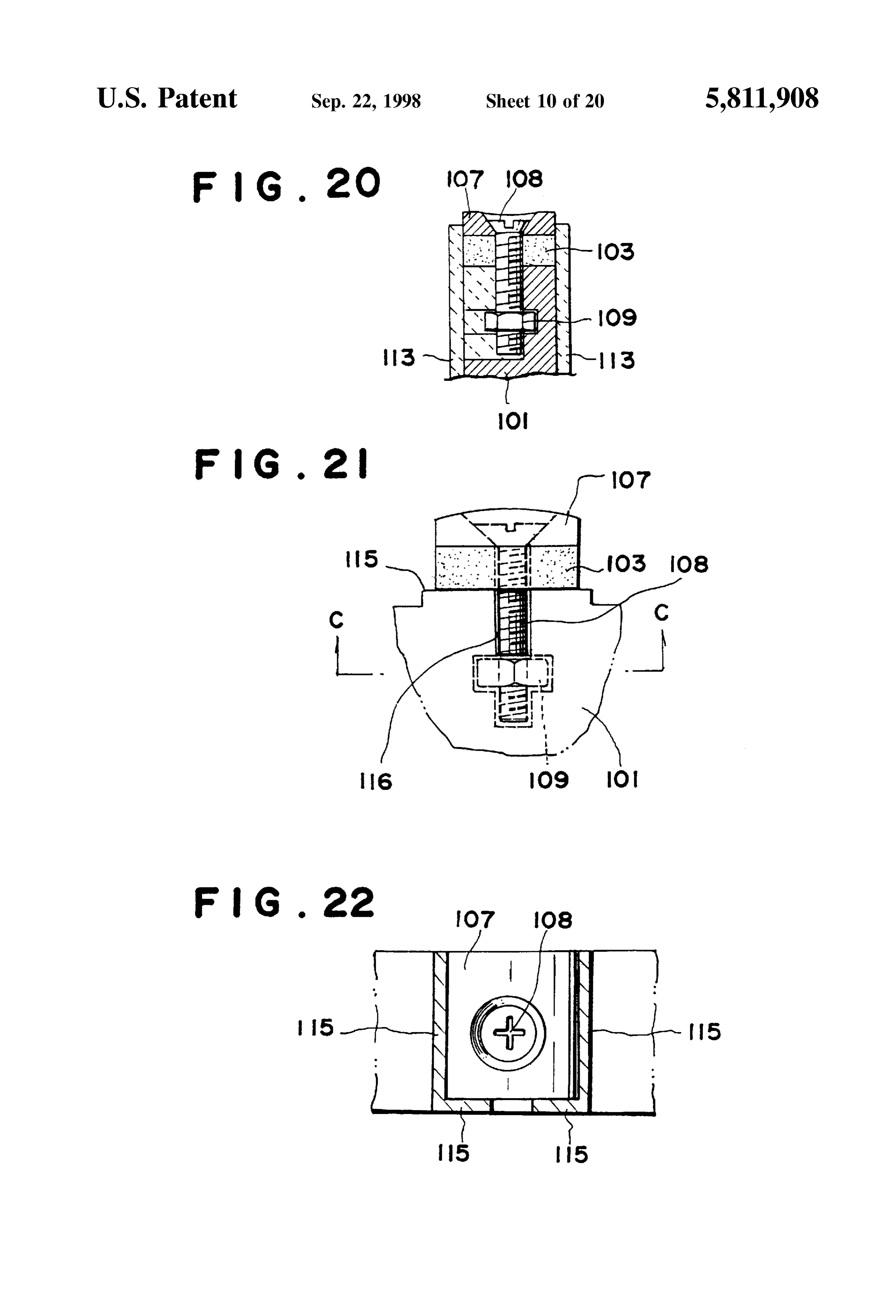
motion operation. Therefore, by pulling up Said extraction part in this engaged condition by Screwing in the Screw part FIG. 21 is a front view of the principal parts showing a through the plate, the extraction of the rotor from the magnetic power generator rotor according to another con crankshaft is made possible. figuration for implementing this invention. Also, the magnetic power generator rotor removal tool of FIG. 22 is a plane View of the magnetic power generator this invention is provided with an engagement protuberant rotor in FIG. 21.
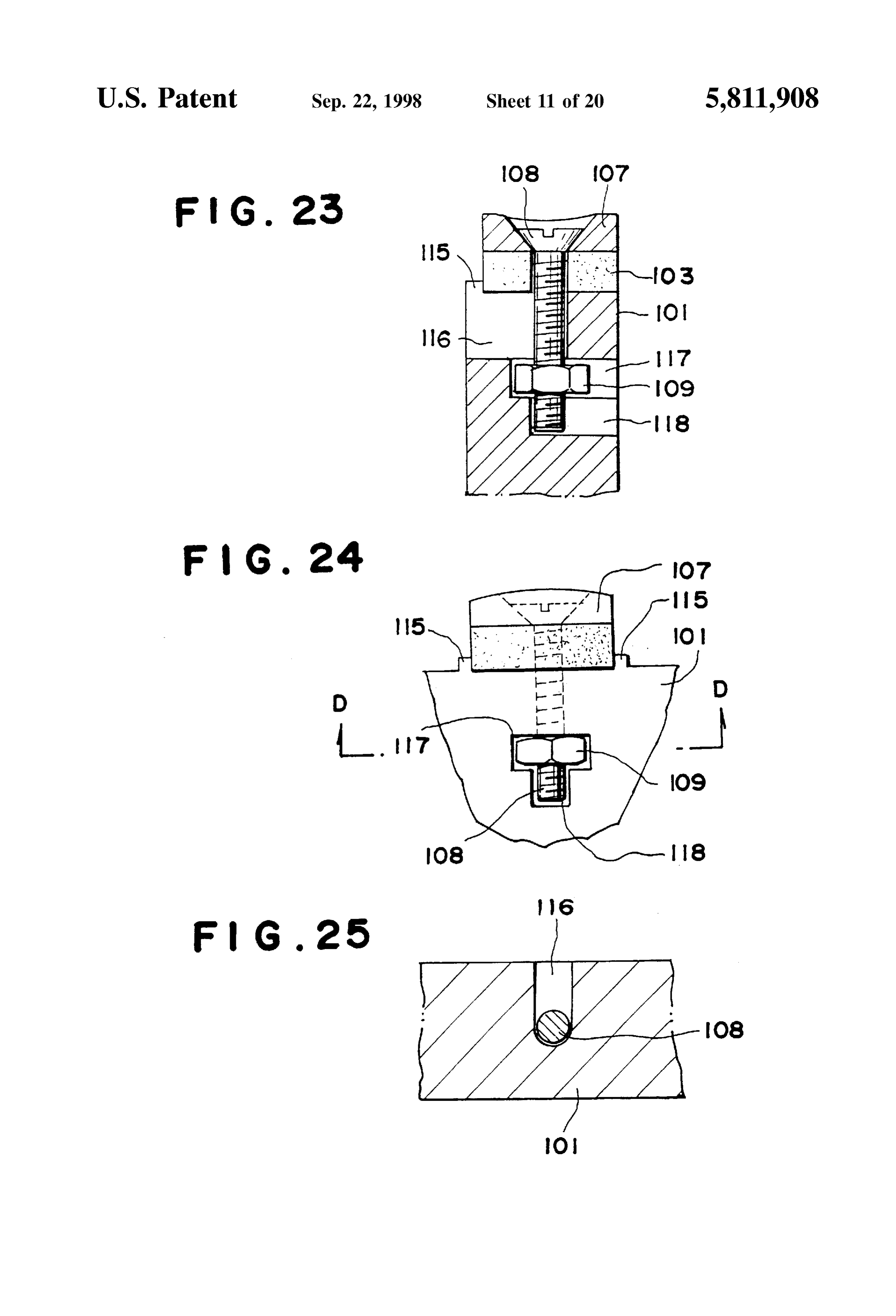
part at the tip of the extraction part that can be engaged in FIG. 23 is a side sectional view of the magnetic power the area of the perforation for removing the rotor by the 25 generator rotor in FIG. 21.
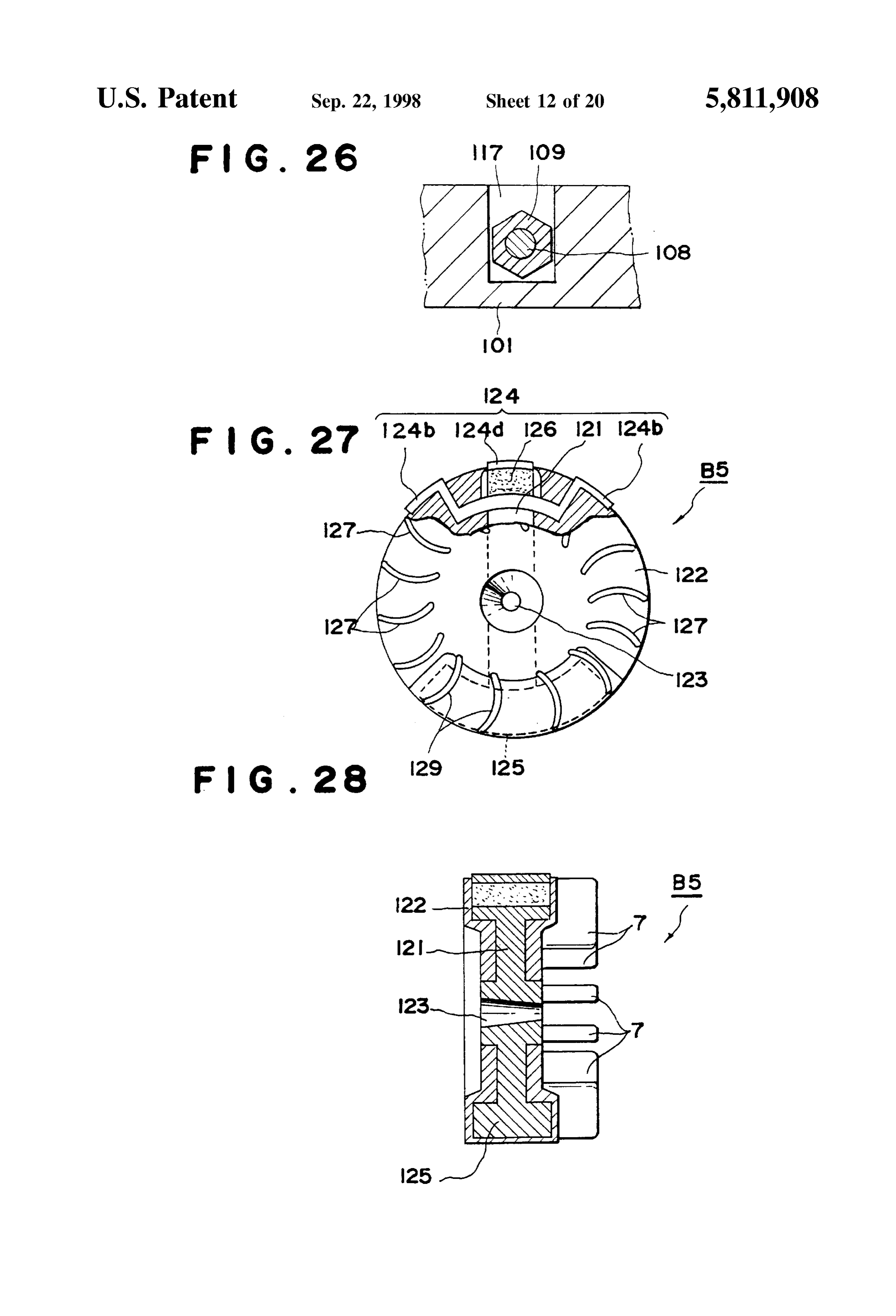
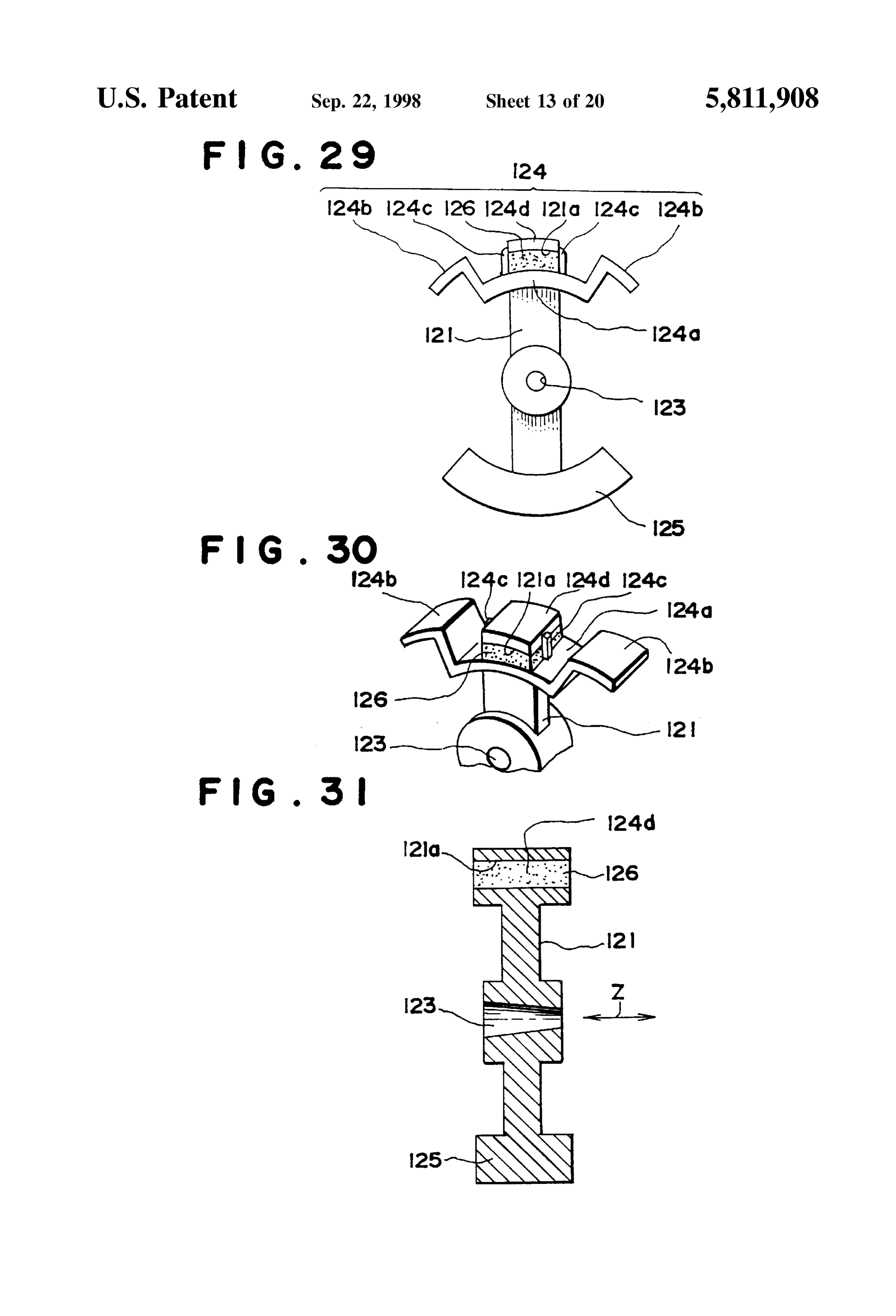
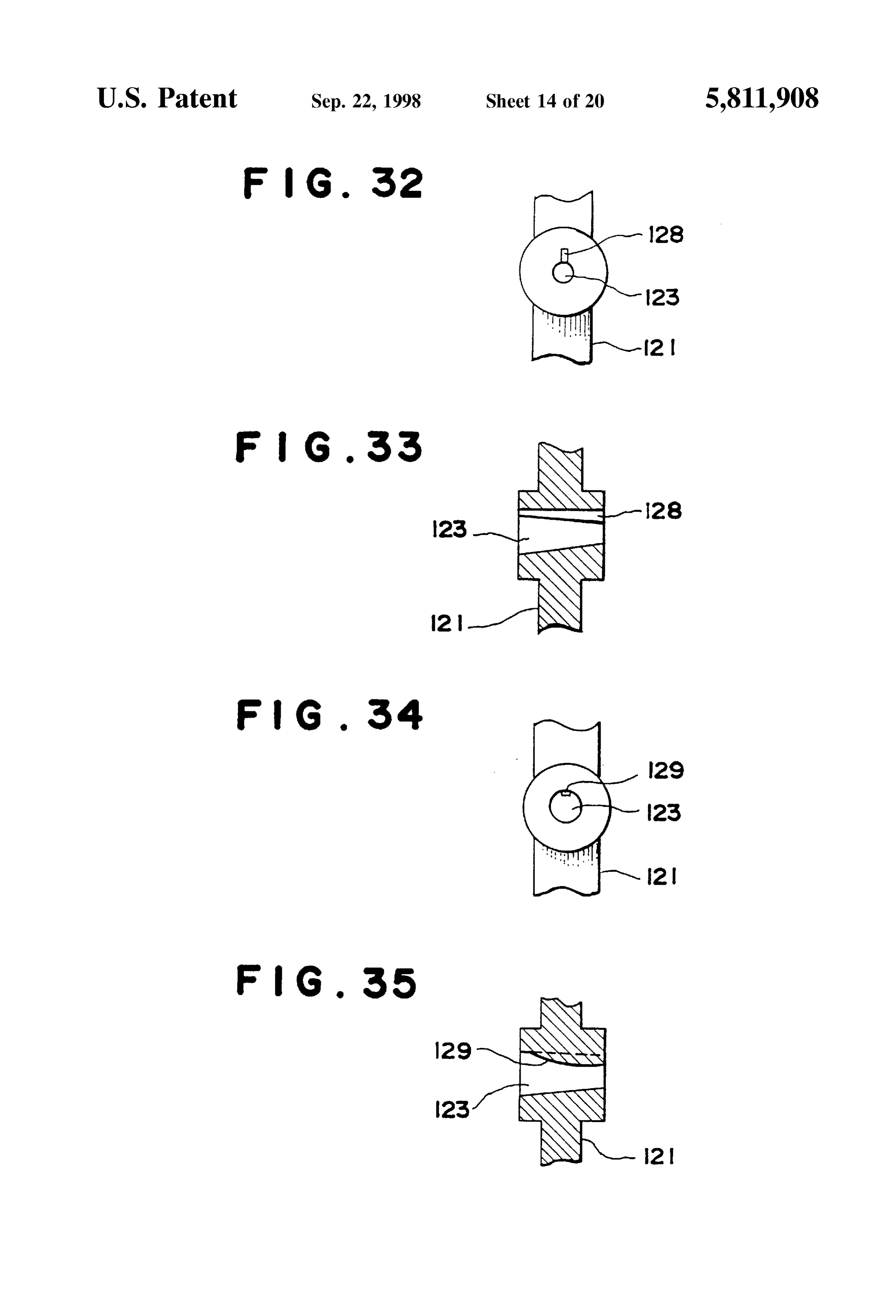
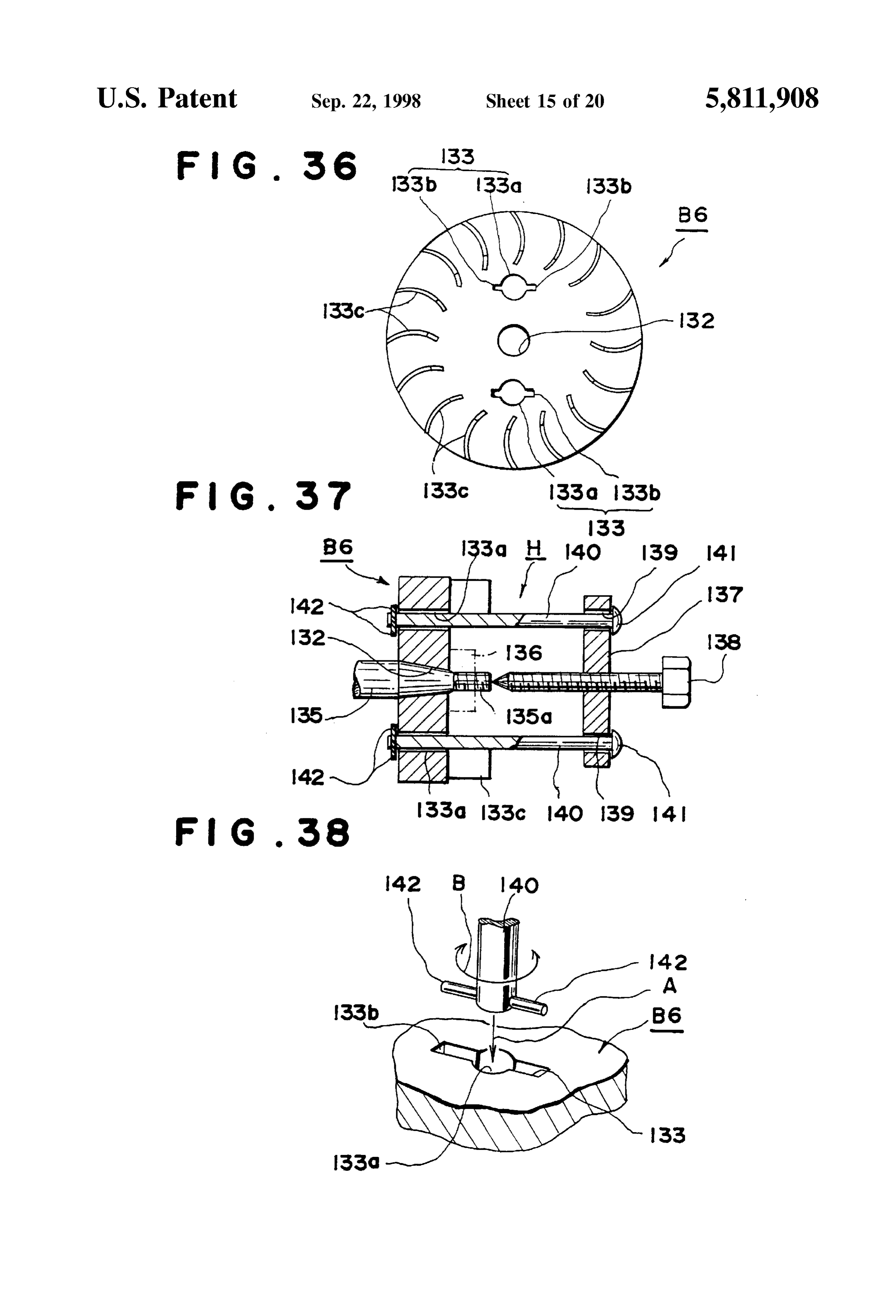
rotation operation of a plate provided with an extraction part. FIG. 24 is a back view of the magnetic power generator Therefore by pulling up Said extraction part in this engaged rotor in FIG. 21 condition by Screwing in the Screw part through the plate, FIG. 25 is a line C-C sectional view of FIG. 21. the extraction of the rotor from the crankshaft is made FIG. 26 is a line D-D sectional view of FIG. 21. possible. FIG. 27 is a front view showing a partially broken down BRIEF EXPLANATION OF DRAWINGS magnetic power generator rotor according to another con figuration for implementing this invention.
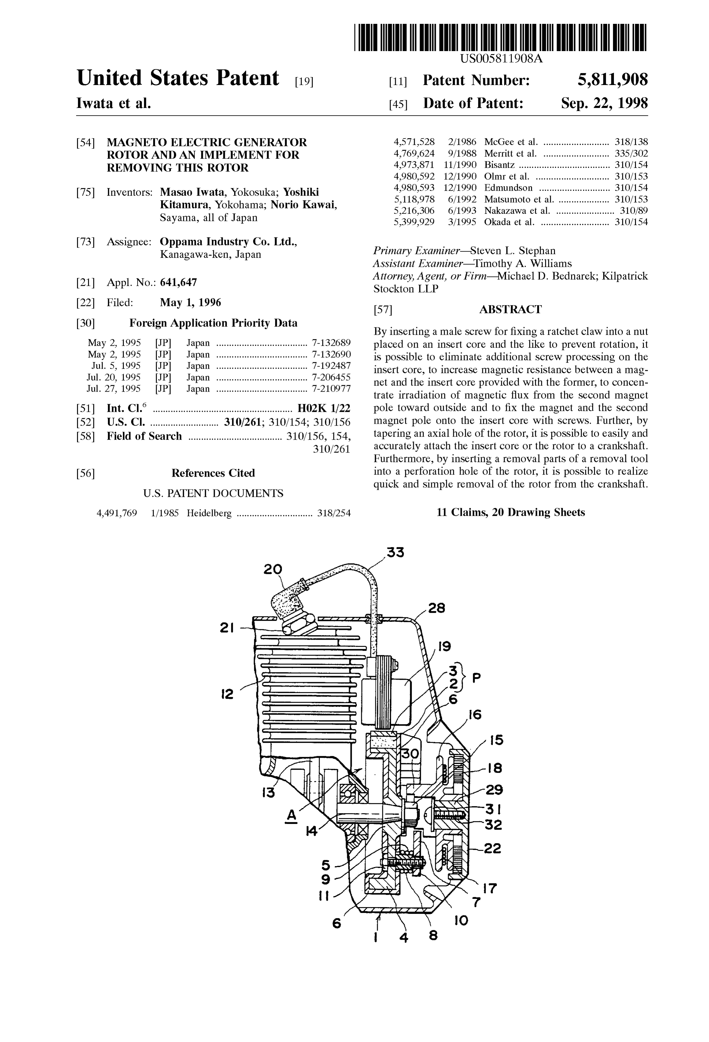
FIG. 1 is a sectional drawing showing a partly broken FIG. 28 is a longitudinal Section view of the rotor shown down Small size engine having a magnetic power generator in FIG. 27 FIG. 29 is a front view showing the insert core rotor in accordance with the configuration for implementing 35 in FIG. 27.
this invention.
FIG.30 is a dismantle view of the principal parts showing
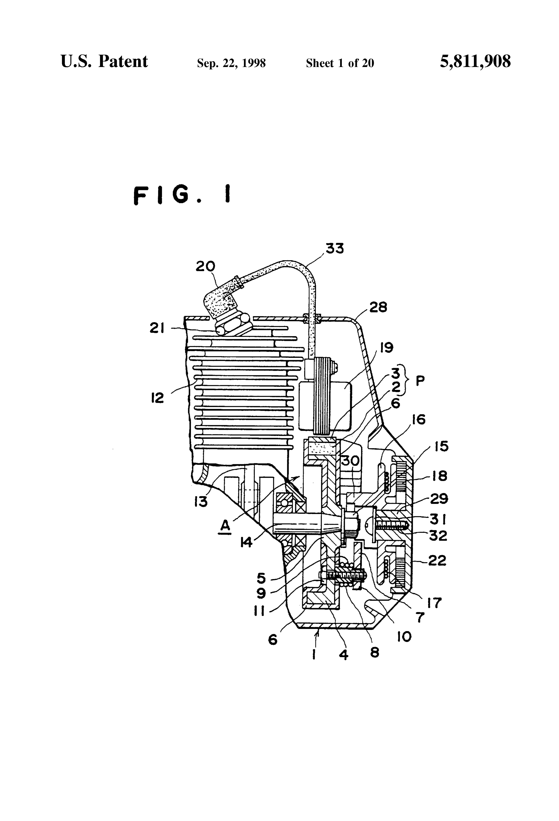
FIG. 2 is a Sectional drawing showing an enlargement of the insert core in FIG. 27.
the principal parts of the rotor in FIG. 1. FIG. 31 is a longitudinal section view showing the insert FIG. 3 is a left side view showing the principal parts of the 40 core in FIG. 27.
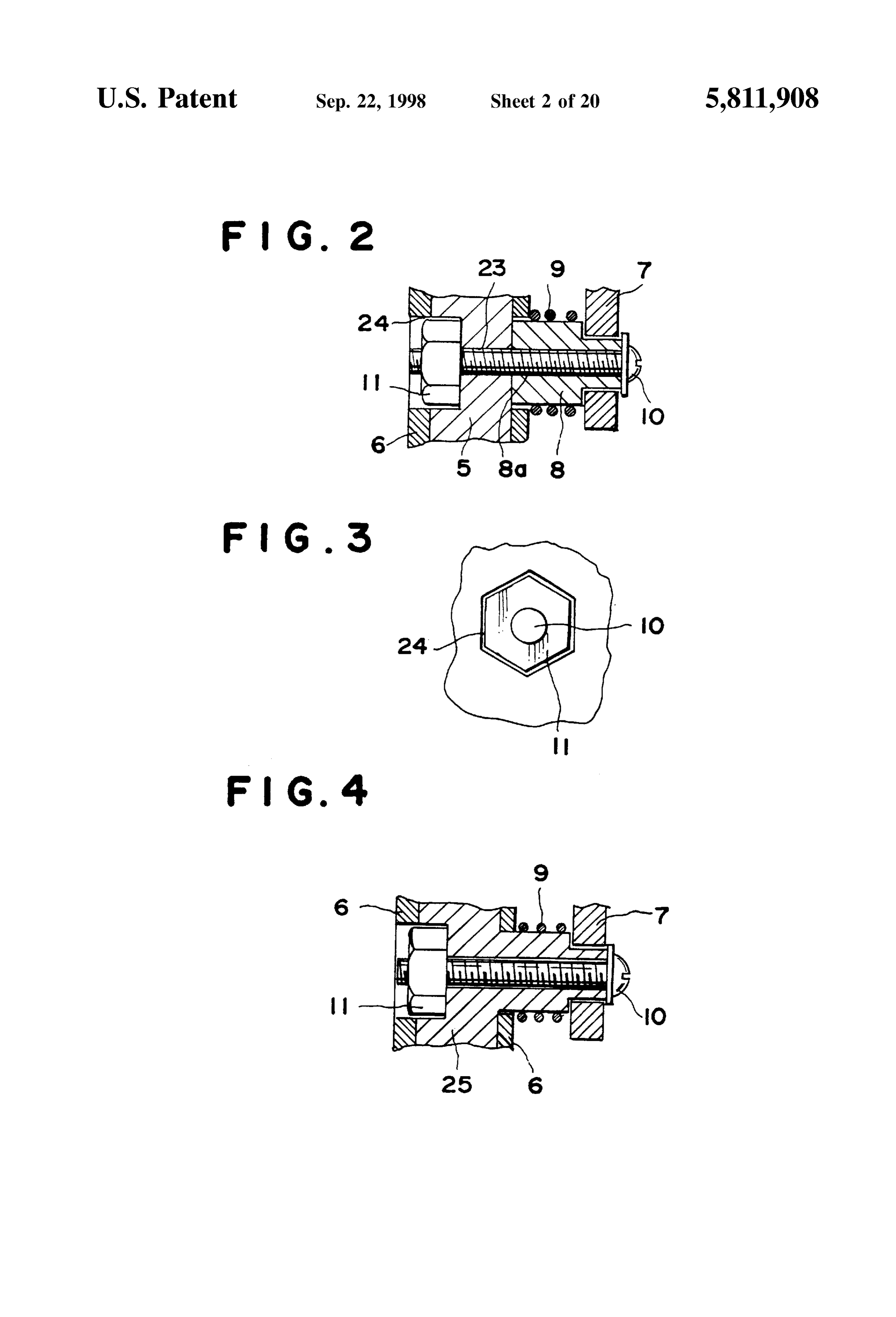
rotor in FIG. 9. FIG. 32 is a front view of the principal parts showing FIG. 4 is a Sectional drawing showing an enlargement of another example of the axial hole part area in this invention. the principal parts of a magnetic power generator rotor FIG. 33 is a longitudinal section view of the axial hole according to another configuration for implementing this part area in FIG. 32.
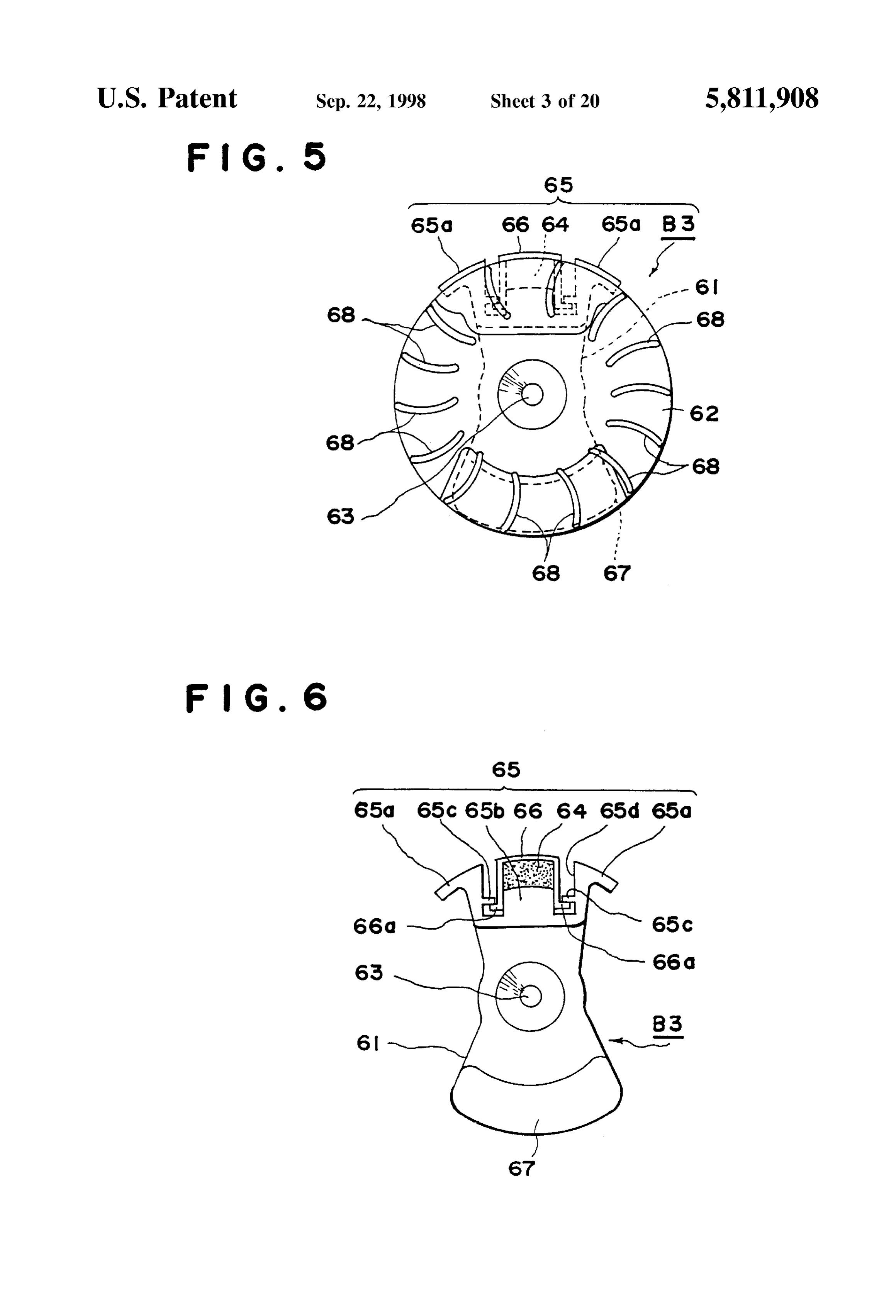
invention. 45 FIG. 34 is a front view of the principal parts shown in FIG. 5 is a front view showing a magnetic power gen another example of the axial hole part area in this invention erator rotor according to another configuration for imple FIG. 35 is a longitudinal section view of the axial hole menting this invention. area in FIG. 34.
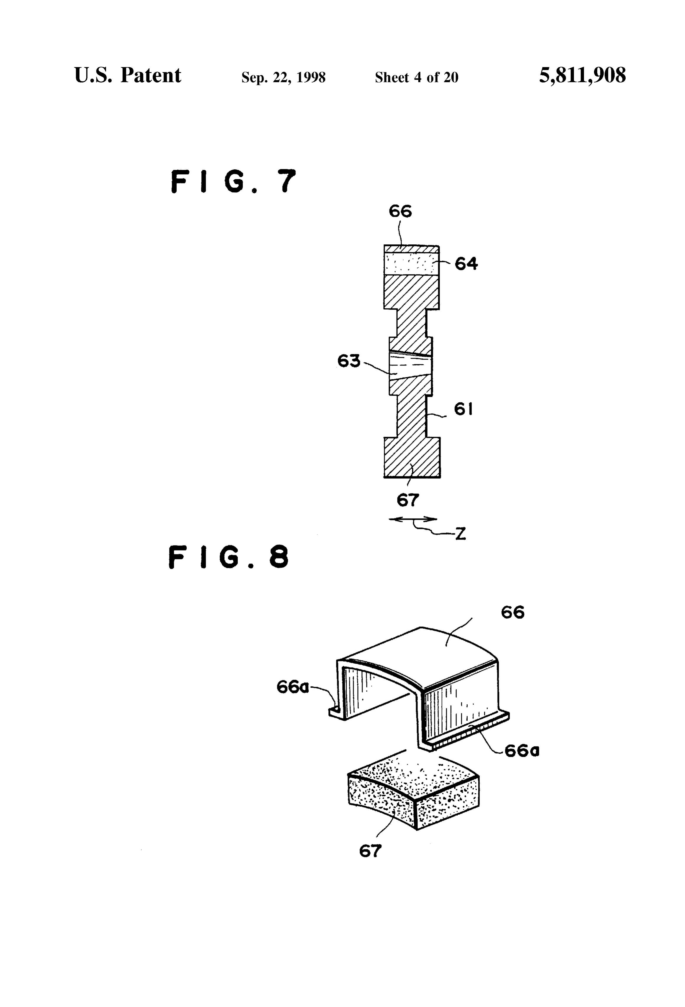
FIG. 6 is a front view showing the insert core in FIG. 5. FIG. 36 is a front view showing a magnetic power FIG. 7 is a longitudinal section view of the insert core 50 generator rotor according to another configuration for imple shown in FIG. 6. menting this invention.
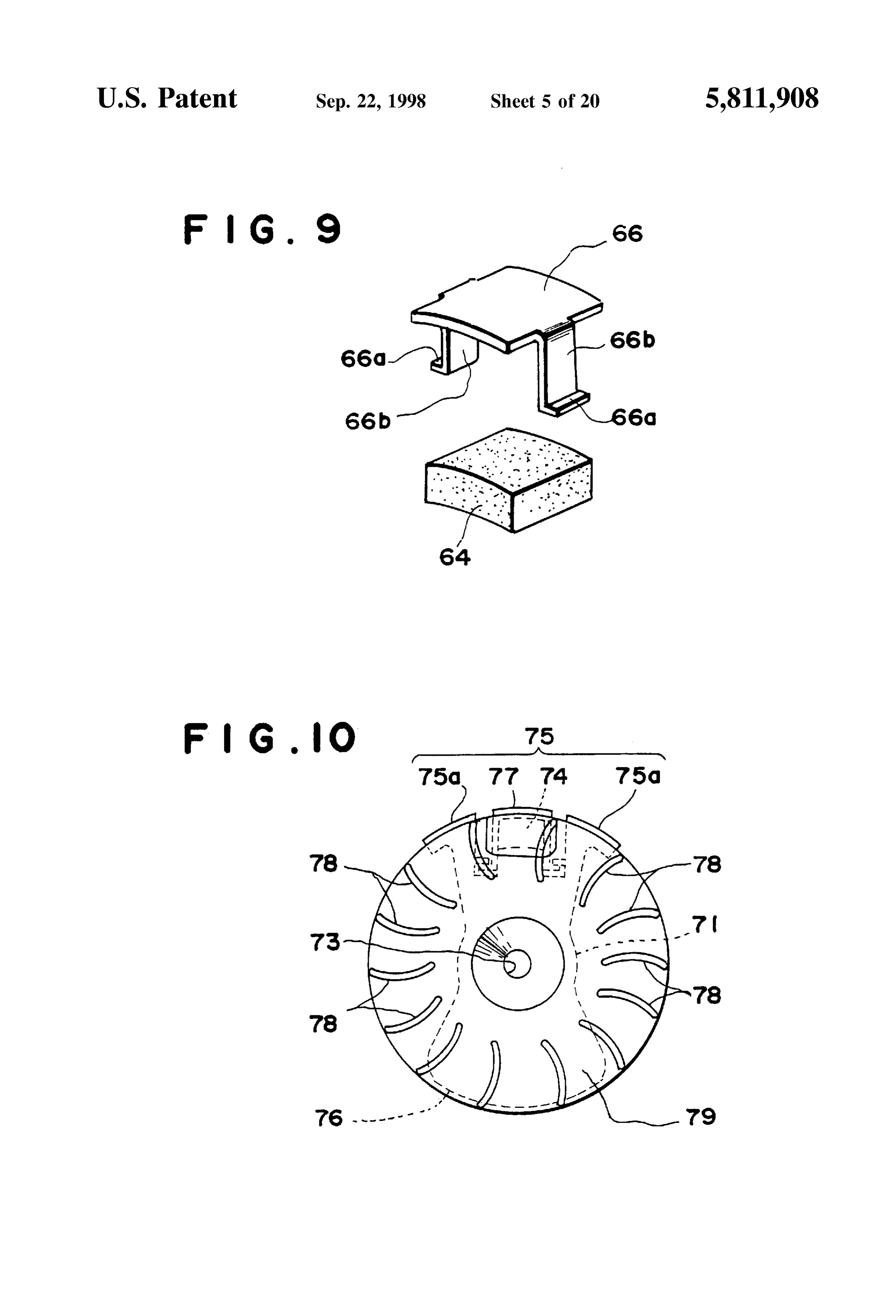
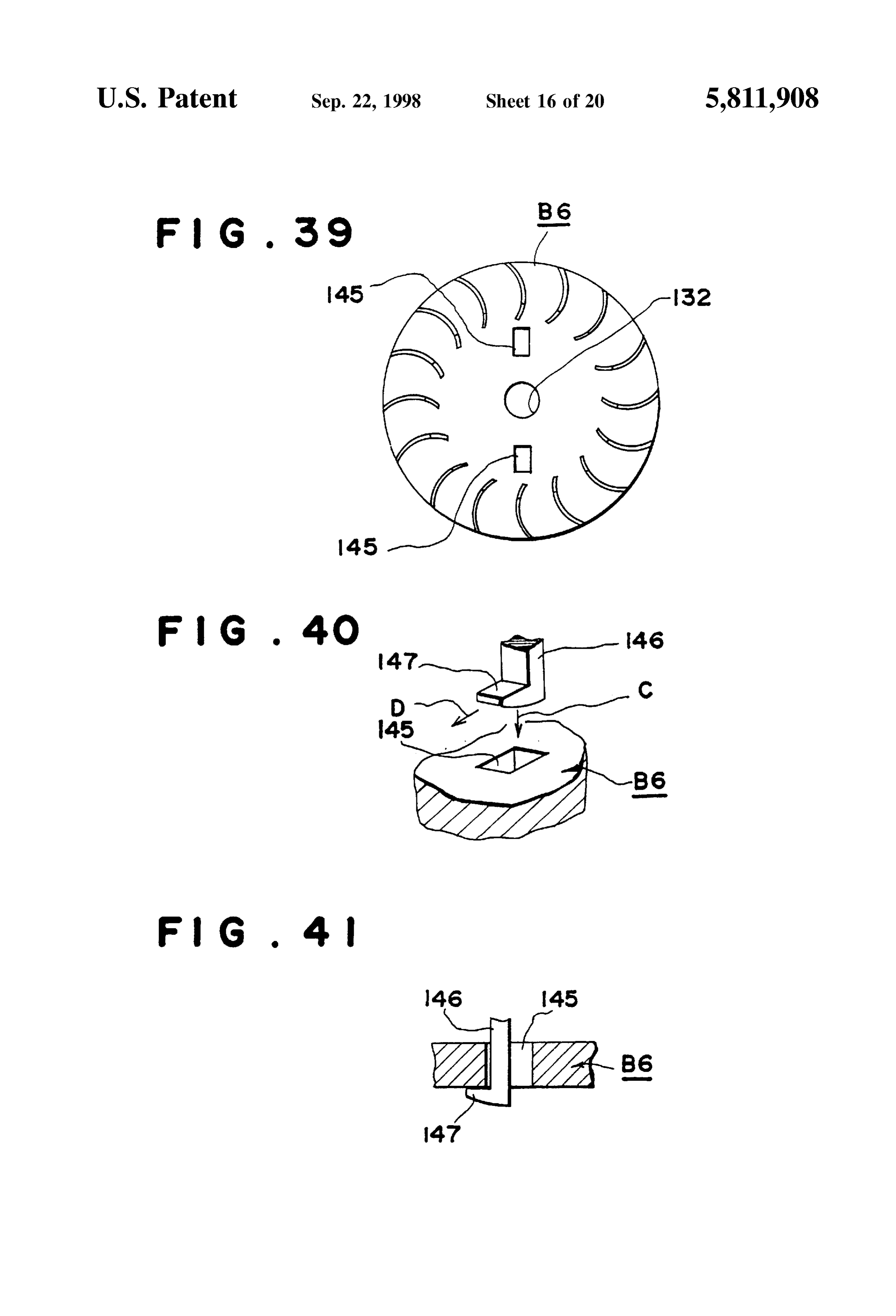
FIG. 8 is a dismantle deal drawing showing an enlarge FIG. 37 is a partially cut off sectional view showing a ment of the magnetic pole and magnet in FIG. 6. magnetic power generator rotor removing tool according to FIG. 9 is a dismantle deal drawing showing an enlarge one configuration for implementing this invention ment of another example of the magnetic pole and magnet 55 FIG.38 is a dismantle view of a principal part showing the in FIG. 6. relation between the perforation for removal and the extrac FIG. 10 is a front view showing a magnetic power tion part in FIG. 37.
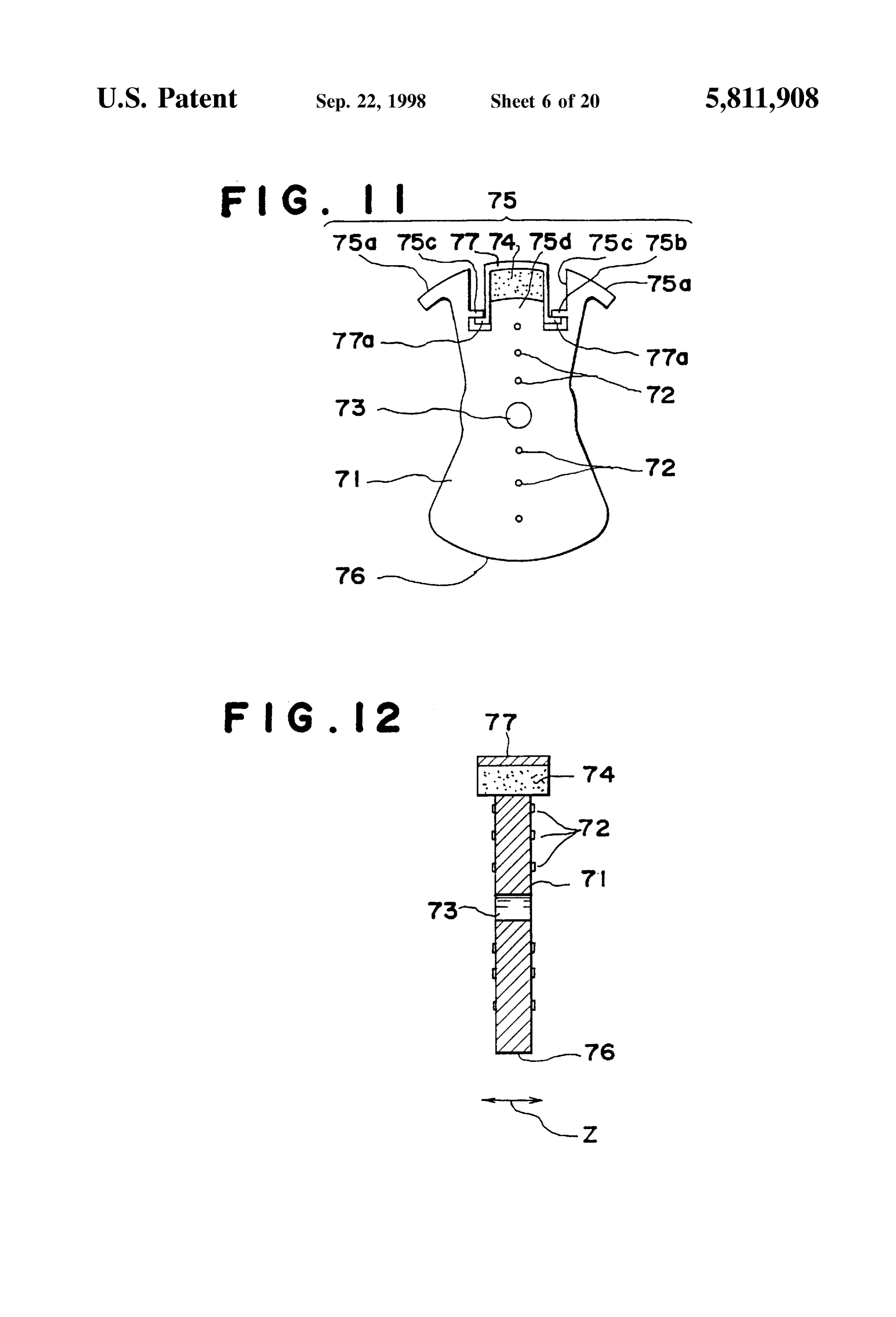
generator rotor according to another configuration for imple FIG. 39 is a front view showing a magnetic power menting this invention. 60 generator rotor according to another configuration for imple FIG. 11 is a front view showing the insert core in FIG. 10. menting this invention.
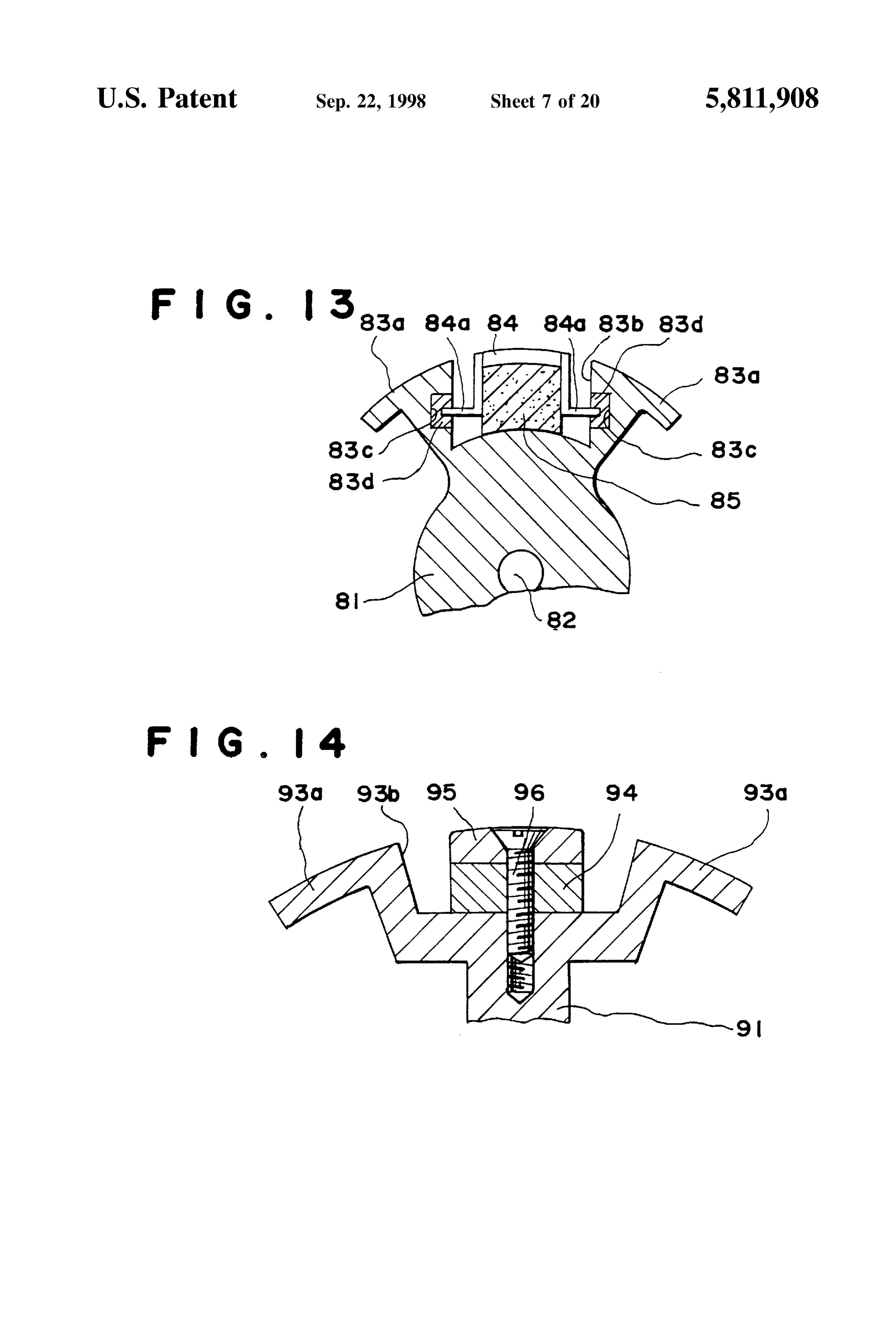
FIG. 12 is a longitudinal section view of the insert core FIG. 40 is a dismantle view of a principle part showing the shown in FIG. 11. relation between the perforation for removal and the extrac FIG. 13 is a front view showing a partially broken down tion part in FIG. 39.
insert core insert core in a magnetic power generator rotor 65 FIG. 41 is a Sectional view of a principal part showing the according to another configuration for implementing this condition of engagement of the perforation for removal and invention. an extraction part in FIG. 40.
Page 26
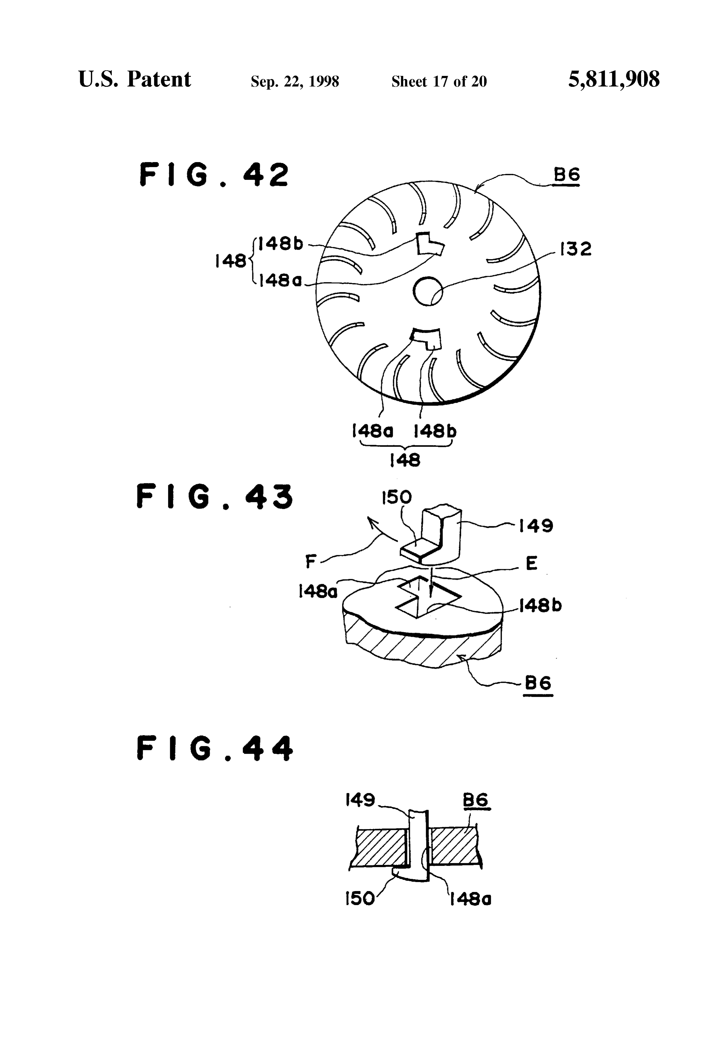
FIG. 42 is a front view showing a magnetic power Next, FIG. 4 is a partial sectional view showing another generator rotor of another configuration for implementing configuration for implementing this invention, and the dif this invention. ference with the above described embodiment is in the point FIG. 43 is a dismantle view of a principal part showing the that the axial part 8 Supporting the ratchet claw 7 in a free relation between the perforation for removal and an extrac rotating manner has been formed into one unit with the insert tion part in FIG. 42 core 5 when forming the latter. In all other respects it is FIG. 44 is a Section view of a principal part showing the identical with the embodiment described above, so a dupli condition of engagement of the perforation for removal and cation of explanation will be omitted. an extraction part in FIG. 43. With Such a construction, the need to prepare said axial FIG. 45 is a sectional view showing a partially broken part 8 as a Separate part will disappear, and it will be possible down conventional Small size engine. to plan a cost reduction by eliminating the number of parts FIG. 46 is a Sectional view showing an enlargement of work. used, and an improvement In the efficiency of assembly part of the rotor in FIG. 45. Further, in the configuration for implementation shown in FIG. 47 is a dismantle view showing an insert core in a FIGS. 1 through 4, an insert core 5 formed by using a conventional magnetic power generator rotor. 15 tempered bonding metal of a magnetic material was shown,
FIG. 48 is a longitudinal section view of the insert core but a layered magnetic plate would also have the same effect shown in FIG. 47. as that described previously.
FIG. 49 is a side view showing a conventional pulley Moreover, in Said configuration for implementation, the removal tool. case where an insert core 5 is covered with a Synthetic resin FIG. 50 is a side view showing a conventional rotor layer that is of a non-magnetic material and formed into a removal tool. disc shape was described, however, as long as it is a
DETAILED DESCRIPTION OF THE
non-magnetic material, anything can be used. For example,
INVENTION it can be covered with an aluminum die cast using alumi
In FIGS. 1 and 2, identical symbols indicated previously 25 Furthermore, Said configuration for implementation are affixed to the parts identical with the past examples in explained the case where an insert core 5 was used with the FIGS. 45 and 46. axial hole between a pole piece part P on one Side and a In rotor A of the magnetic power generator of the con counter weight part 4 on the other Side, however it goes figuration according to this implementation, a ratchet claw 7 without Saying that the present invention can also be applied is provided as shown in FIG. 2 to an axial part 8 having a when the pole piece part P and the counter weight part 4 are perforation 8a as it cylindrical part. Moreover, 10 is a male Separated.
screw pushed through a perforation 23 which is formed by FIG. 5 is a front view showing a magnetic power gen a perforation 8a of said axial part 8 and an insert core 5. erator rotor B3 according to another configuration for imple Furthermore, 11 is a nut which is screwed on the end of menting this invention, and in Said drawing 61 is an insert Said male Screw 10 and Secures Said axial part 8 to Said insert 35 core made from a magnetic Sintered alloy forming an core S. Moreover, a nut 11 is located in a rotation blocking approximately I-shape as a whole, and 62 is a non-magnetic hole 24 formed in said insert core 5, and blocks rotation material layer Such as a Synthetic resin layer and aluminum despite the Screwing in operation of Said male Screw 10. die cast layer formed by ejection to cover the insert core 1. FIG.3 shows a hexagonal concave shape slightly larger than 40 Also, with said insert core 61, an axial hole part 63 is said nut 11. between a pole piece part 65, with a magnet 64 on one Side, Also, said rotation blocking hole 24 can be formed with facing a counter weight part 67 on the other Side The Said a non magnetic layer 6 Such as Synthetic resin and aluminum pole piece 65, as shown in FIG. 6, has a pair of approxi wit lout providing an insert core 5. mately L-shape magnetic poles 65a projecting at one end of Consequently, in the rotor of a Small size engine with Such 45 an insert core 61, a concave part 65b for attachment indented a construction, in case Said ratchet claw 7 is installed on the between Said magnetic poles 65a, a pair of engagement insert core 5, first the ratchet claw 7 is attached to said axial blocking protuberance 65 projecting from the opposite walls part 8 in a freely rotating manner, then the male screw 10 is in Said concave part 65b for attachment, and a magnetic Screwed through the axial part 8. receptacle part 65d protruding from the bottom part of Said Next, after inserting said male screw 10 into the perfo 50 concave part 65b for attachment.
ration 23 which has been pre-formed in the insert core 5, the Also, 66 is a magnetic pole formed in an approximately nut 11 is screwed on to the end of Said male Screw which is horseshoe shape by a magnetic material as a whole, and as protruding out from the insert core 5. shown in FIG. 8 at both ends are installed engagement Said Screwing on action can be easily and quickly effected pieces 66a, which can be engaged with Said engagement by screwing on the male screw 10 to the nut 11, which has 55 blocking protuberance 65c.
been installed in the rotation blocking hole 24, through the Further, 64 is a magnet and when the engagement piece axial part 8. 66a is engaged with Said engagement blocking protuberant Therefore, according to the configuration of this 65c, the magnet 64 will be held between the bracket-shaped embodiment, there is no need to purposely carry out the part of Said magnetic pole 66 and the receptacle Surface of Screw thread process for the male Screw in order to Screw the 60 Said magnetic receptacle part 65d.
male Screw 10 on to the insert core 5, and said ratchet claw In short, Said magnetic pole 66 is formed independently of 7 can be easily Secured. insert core 61, and when assembling the rotor it is attached Further according to the configuration of this to Said insert core 61, and at the point of attachment embodiment, the shape of Said rotation blocking hole 24 is (separate part) the magnetic resistance of the magnetic shown as being hexagonal, but it can be any shape if the 65 circuit will increase.
rotation blocking effect can be achieved when the nut 11 is Furthermore, Said magnetic pole 66 and the magnet 64 embedded. form one part of Said pole piece 65, and the magnet pole 66
Page 27
comes close to a power generating coil and ignition coil it is possible to drastically improve the power generating which are not shown in the drawings and functions to capability of each coil.
generate Voltage. Moreover, in order to further reduce the shortage part in An insert core 61 having, a pole piece part 65 and a the magnetic circuit it is also possible to narrowly control the counter weight part 67 as shown in FIGS. 6 and 7, is Start up piece 66b of the magnetic pole 66 covering the Side positioned in a metal mold that is not shown in the drawing of said magnet 64 as shown in FIG. 9. and each part excluding the axial hole part 63 is ejection FIG. 10 is a rotor showing another configuration for formed, or aluminum die cast formed, and a disc shape rotor implementing this invention, and the insert core forming this coated with a non-magnetic material layer 62 as shown in rotor, as shown in FIG. 11, blocks a multiple layered FIG. 5 is formed. magnetic plate with a rivet 72 and is composed of layers. Also, 68 is a cooling fan formed Simultaneously when Even in this configuration of embodiment, excluding the enjection forming or aluminum die cast forming Said Syn axial hole part 73, said insert core 71 is formed in a disc thetic resin and protrudes in an ideal shape to carry out the shape covered by a non-magnetic layer 79 and the axial hole cooling of the internal combustion engine. part 73 is between a pole piece part 75 having a magnet 74 15 on one side and a counter weight 76 on the opposite Side.
Also, the axial line directional Z length of Said magnet 64 is equal with the magnet 65a and 66; therefore, the magnetic a pair Said pole piece part 75 has, as shown in FIGS. 11 and 12, flux of the magnet 64 is concentrated in magnetic pole 66 of approximately L shape magnetic poles 75a pro and can affect the ignition coil and power Venerating coil, truding at one end of an insert core 71, a concave part 75b that are not shown in the drawing, with high efficiency. for attachment indented between each of Said magnetic poles Also, Said counter weight part 67 has the necessary and 75a, from an engagement blocking protuberant 75c projecting a pair of walls facing each other in Said concave part
Sufficient weight to match the weight of Said pole piece part 75b for attachment, and a magnet receptacle part 75d 65 and is designed to improve the inertial moment of the insert core 61, and is formed in an approximately arc shape projecting attachment.
from the bottom of said concave part 75b for as a whole. 25
Also, 77 is a magnetic pole formed in an approximately
The insert core 61 having the axial hole part 63, the pole horseshoe shape by a magnetic plate, and at both ends, as piece part 65 and the counter weight part 67 is formed by a shown in FIG. 7, an engagement piece 77a, which can be magnetic piece made from a sintered alloy as one unit using engaged with Said engagement blocking protuberant 75c, is one metal mold as described previously. provided.
Also, Said axial hole part 63 is a tapered hole whose inside 74 is Said magnet, which is Secured between the bracket diameter changes in the direction of the axial fringe as shaped part of Said magnetic pole 77 and the receptive described previously. Because this tapered hole is formed by Surface of Said magnet receiving part 75d at the time of the metal mold simultaneously when forming said insert engaging the engagement piece 77a with Said engagement core 61, it becomes possible to smoothly finish the inside blocking protuberant 75c 78 is a fan used for feeding air, and Surface. 35 79 is a non-magnetic material layer.
For this reason, when installing a rotor B3, having Such a Further, said magnetic pole 77 and magnet 74 also com tapered hole as the axial hole part 63, under pressure on the prise a part of Said pole piece part 75, and magnetic pole 77 crankshaft 14 of the internal combustion engine, a part of the approaches near a power generating coil and an ignition coil tapered hole will be in tight contact with the outer surface of which are not shown in the drawing and forms a magnetic the crankshaft 14. For this reason Said rotor can be accu 40 circuit for generating Voltage.
rately attached to is designated position on the crankshaft. In this configuration of embodiment, the axial line direc Also, the outer Surface part of each of Said magnetic poles tional Z length of the magnetic pole 77 and the magnet 74 65a and 66 is slightly exposed outside of Said non-magnetic are equal, and moreover is greater than the thickness of the material layer, and thus is able to efficiently Supply the 45 insert core 71, therefore it is possible for the highly dense magnetic flux of the magnet 64 to the power generating coil flux generated by magnet 74 to adequately affect Said power and the ignition coil. Consequently, it is possible to increase generating coil and the like through magnetic pole 77 having the power generating efficiency of each of these coils. a weak magnetic resistance (the mutual contact area is A magnetic power generator rotor B3 with Such a con equal).
Struction is attached to the crankshaft 14 of an internal 50 FIG. 13 shows another configuration for implementing combustion engine and rotates as described above and this invention. In Said drawing, 81 is an insert core made adequately affects the magnetic flux from the magnetic pole from Sintered alloy of non-magnetic material or a layered 66 on to the power generating coil and ignition coil posi magnetic plate. In this insert core 81, 82 is an axial hole part tioned in the area of the rotor B3 and generates an induced Such as a tapered hole or Straight hole and the like, 83a is a power of a pulse form in each of these coils. 55 pair of L shape magnetic poles provided at one end of insert In this case, Said magnetic pole 66 is formed into one unit core 81, and 83b is a concave part for attachment formed with the magnet 64 which is installed in the magnetic between each of the magnet poles 83a.
receptacle part 65d of the insert core 61 by its engagement Also, 83a is a cut off part formed on the facing walls of piece 66a. the concave part 83b for attachment, 84 is a horseshoe shape For this reason, the magnetic resistance of the magnetic 60 magnetic pole Supported by Said facing walls 83b in Such a circuit at the part of engagement of this engagement piece manner that the engagement pieces 84a at both ends seem to 66a and the engagement blocking protuberant 65 that blockS be biting into the non-magnetic part 83d provided in the cut the engagement becomes great. In short, the shortage part of off part 83a and which is made of magnetic plates. the magnetic circuit can be lowered and Virtually all of the Also, 85 is a magnet which is held between Said magnetic magnetic flux generated by the magnet 64 engagement, and 65 pole 84 and the bottom part of said concave part for thus it is possible for the magnetic flux passing through this attachment 83b. Magnetic poles 83a, 84 and magnet 85 form magnetic pole 66 to adequately affect Said coils. As a result, the pole piece part.
Page 28
The insert core 8 I comprised thus is identical with each 107a are provided. Said screw 108 is inserted into these of Said configurations for embodiment, and over these are perforations 103a and 107a and a nut 109 is attached to a provided a non-magnetic layer by ejection forming of Syn suitable position on said screw 108.
thetic resin or aluminum die casting to prepare a disc shape To the insert core 101 are installed from the side using a rOtOr. fising tool, the assembled unit of said magnet 103 and the In this configuration of embodiment, by providing a second pair of magnetic poles 107 provided with said screw non-magnetic part 83d, Such as that described previously 108 and nut 109 so as to place the magnet 103 between the between the magnetic pole 84 and the magnetic pole 83a, the ribs 110 for prevention of a shifting in position provided magnetic resistance at the engagement blocking part between the first pair of magnetic poles 106 in the pole piece (connecting part) becomes very strong.
Consequently, the flow of magnetic flux from the mag part 104 of said insert core 101; and also the screw 108 is installed So as to be placed in the concave hole part 111 and netic pole 84 to the magnetic pole 83a is reduced. In short, the shortage part of the magnetic circuit becomes Small and theNext, nut 109 in the concave hole part 112. it becomes possible for much of the flux from magnet 85 to poles 107Said magnet 103 and the Second pair of magnetic installed with said fixing tool is to be secured but pass through magnetic pole 84 and be adequately concen 15 trated in Such as the power generating coil and the like. in the case of this invention these can be tightened and fixed FIG. 14 shows a configuration of another embodiment of by Simply turning Said Screw 108 in a tightening direction against the nut 109 that is restricted from turning by the this invention. This configuration of embodiment places a magnet 94 and a magnetic pole 95 of about the same size on concave hole part 112.
top of one another in order at the bottom part of the concave That is, because the concave hole part 112 that fits in said part for attachment 93b formed between a pair of L shaped nut 109 provided in said insert core 101 is, as shown in magnetic poles 93a, and by Screwing these to the bottom of FIGS. 16 and 17, a hole that has been made only slightly Said bottom part with a non-magnetic material Screw 96, larger than the opposing aforementioned nut 109. The made of Such as StainleSS Steel and the like fixes the magnet opposing part of the nut 109 comes in contact with the wall 94 and the magnetic pole 95 to the insert core 91. of said concave hole part 112 and even when the screw 108 This configuration of embodiment is able to virtually 25 is tightened said nut 109 itself does not rotate. avoid magnetic shortages in the magnetic pole 95 and the On one hand, because the concave hole part 111, in which insert core 91 because the magnetic pole 95 is attached to the said Screw 10S fits into, has a clearance for said 108 to insert core 91 through a non-magnetic Screw 96 AS a result, smoothly rotate in as shown in FIG. 18, no difficulty the magnetic flux from the magnetic pole 95 can be whatsoever occurs in the tightened fixture of Said magnet adequately concentrated in the power generating coil and the 103 and the like.
like, and can achieve the original excellent power generating Furthermore, if the position of said concave hole part 112 capacity FIGS. 15 through 20 show a magnetic power is located in a place away from the magnetic field of Said generator rotor B4 according to another configuration for magnet 10)3, a magnetic body can be used. Also, Said axial implementing this invention. 101 is an insert core and is 35 hole part 102 was made a tapered hole for easy release of the comprised of the pole piece part 104 and the counter weight mold when forming, but it can also be a Straight hole. part 105 that have the axial hole part 102 between them and Next, the assembled insert core 101 including such as said secure the magnet 103. magnet 103 and the magnetic poles 107, is Set up to expose Also, 106 is the first pair of magnetic poles formed as one a part of the Outer-most part of the first pair of magnetic unit with said insert core 101, and 107 is the second pair of 40 poles 106 and the second pair of magnetic poles 107 of the magnetic poles made of a magnetic material and fixed insert core 101 to the metal mold for ejection molding use between Said first pair of magnetic poles 106 through Said which is a non-magnetic material Such as for example magnet 103 by a non-magnetic screw (bolt) 108 and a nut Synthetic resin, and the outer shape is formed into a disc 109, and is press formed. shape as shown in FIG. 20 by the ejection forming of the Furthermore, 110 are ribs for preventing a shift in position 45 Synthetic resin. The rotor is completed in this way. provided on the attachment Surface of Said magnet 103 So as Further, depending on needs, the provision of a cooling to bring said magnet 103 between the ribs, 111 are concave fan for engine cooling to Said disc shape rotor is optional. hole parts engaging Said Screw 108, and 112 is a concave Generally, a pre-magnetized magnet is used for Said hole part that is wider than Said concave hole parts 111. magnet 103 but depending on the case, there are times when These are also open at the other side of the insert core 101. 50 a magnetic body that has not been magnetized is used. In 113 was formed by carrying out Such as ejection forming Such case, the magnetic body can be magnetized into a into disc shape on the assembled insert core 101, and is for magnet after Said ejection forming.
example a Synthetic resin layer of non-magnetic material as Also, in Said configuration of embodiment, a case carry shown in FIG. 20. ing out ejection molding with Synthetic resin, which is a Next, the procedure for assembling said insert core 101 55 non-magnetic body, was shown, but ejection molding with will be described. First, said insert core 101 is formed with Such as the conventional aluminum die cast can be carried a powder Such as for example iron oxide that is a magnetic without being restricted to Synthetic resin to achieve the material using a metal mold with a pole piece part 104 Same results as that in Said configuration of embodiment. having the first pair of magnetic poles 106 as shown in the FIGS. 21 through 26 show another configuration of the drawing, the concave parts 111 and 112 as shown in FIG. 60 magnet 103 and the magnetic poles 107. In this configura 195 for installing a screw 108 and a nut 109, the ribs 110 for tion of embodiment, the ribs 113 for preventing a slip in preventing a shift in the position of the magnets provided position have been provided to prevent the bottom part of between said first pair of magnetic poles 106, and for said magnet 103 from shifting in the direction of the thrust example a tapered axial hole part 102, and a balance weight (one thrust direction in this configuration of embodiment) 105 on the other side of Said axial hole 102. 65 and in the direction of interSection. Also, at about the center between said magnet 103 and the Also, in this configuration of embodiment, on one side of second pair of magnetic poles 107 perforations 103a and said ribs 115 for preventing a shift in position in the thrust
Page 29
direction and the insert core 101, as shown in FIGS. 23 and hole is formed by the metal mold simultaneously with the 25, a concave hole part 116 has been provided enabling the fonTilnu of said insert core, it is possible to finish the inside insertion of a screw 108 attached to said magnet 103. Surface Smoothly.
On one hand on the other side of Said insert core 101, as For this reason, a part of the tapered hole part of the rotor shown in FIGS. 24 and 26, there is provided a concave hole having such a tapered hole as the axial hole part 123 w 11 part 117 enabling said nut 109 to be inserted from the other fit tightly so as to bite into the outer surface of the crankshaft side and a concave hole part 118 in which the bottom end of when installing on the crankshaft of an internal combustion said Screw 108 is seated. engine. Consequently, Said rotor can be accurately installed In this configuration of embodiment, first the nut 109 is in the established position on the crankshaft. inserted in said concave hole part 117 from said other side An insert core 121 such as shown in FIGS. 29 through 31 of the insert core 101, next the screw 108, which has been is positioned with a metal mold that is not shown in the passed through Said magnet 103 and the Second magnet drawing, and each part excluding the axial hole part 123 is poles 107, is screwed in from said one side, then at this time ejection formed with Synthetic resin, or formed by alumi the end of the Screw 108 is Screwed into the nut 109.
num die casting, and coated with a non-magnetic material
Subsequently, with said second magnetic poles 107 in the layer 122 such as shown in FIGS. 97 and 28, to form a disc condition of being positioned in the ribs 11 S for preventing shape rotor.
a shift in position, by screwing said screw 108 into said nut Also, a multiple of cooling fans 127 are formed as one 109 with a tool, said magnet 103 can be fixed firmly in the unit on one side of this disc shape non-magnetic material insert core 101 without resulting in a shift of position. layer 122. These cooling fans 127 provide ventilation with In other words, in this configuration of embodiment, the the rotation of Such a rotor, and is used for cooling the ribs 115 for preventing a shift in position, which have been engine.
provided at the established position for the insert core 101 of Also, the outer Surface part of Said magnetic poles 124b the magnet 103, can be easily prevented from shifting in and 124d are slightly exposed on the outside of Said non either the from, back, left or right direction when assembling 25 magnetic material layer 122, and thus can efficiently Supply the magnet 103 with the screw 108 and the nut 109 without the magnetic flux from the magnet to the power generating using an engagement tool. Therefore, the magnet 103 and coil and the ignition coil and the like. Consequently, it is the second magnetic poles 107 will be safely secured in their possible to raise the power generating efficiency of each of established positions even after assembling. these coils.
FIGS. 27 and 28 show another configuration of embodi Also, the axial hole part 123 provided at the center part of ment of a magnetic power generator rotor B5, and 121 is an an insert core 121 Such as described above has a tapered insert core having an approximately H shape as a whole, and hole, but as shown in FIGS. 32 and 33 by forming as one unit 122 is a non-magnetic material layer made of Synthetic resin, a key groove 128 in the axial direction in the axial hole part aluminum die cast and the like which has been ejection 123 when forming said insert core 121, the rotation block on molded in disc shape So as to cover the insert core 121. 35 the crankshaft of the rotor can be made reliable when fitting Also, Said insert core 121 has on one side a pole piece 124 to the key protuberant pre-formed on the crankshaft. having a magnet 126 and on the other opposite Side a counter Further, in case a key protuberant cannot be provided on weight 125 with an axial hole part 123 between them. the crankshaft itself, by inserting a piece in the key groove Of these, as shown in detail in FIGS. 29 30 and 31, the 128 the rotation block for the rotor against said crankshaft pole piece 124 is comprised of the L shape magnetic poles 40 can be reliably accomplished.
124b protruding from both ends of a 1 shape magnetic pole Also, as shown in FIGS. 34 and 35, by providing the key piece 124a, the magnetic poles 124d as magnetic material protuberant 129 as one unit in the axial direction in Said axial (plates) Supported by the Supporting column 124c erected as hole part 123 at the time of said forming, the blocking of one unit on Said magnetic pole piece 124a, and the magnet 45 rotation of the rotor on the crankshaft can be reliably 126 provided in an open hole 121 a formed between the accomplished when fitted to the key groove pre-formed on magnetic piece 124a, the Supporting column 124c and the the crankshaft.
magnetic pole 124d. Further, said key groove 128 and key protuberant 129 can Here, this magnet 126 is equal in axial line directional be formed simultaneously with the forming of the length with each of the magnetic poles 124b and 124d, 50 crankshaft, therefore the processing Steps for the rotor will therefore the magnetic flux from magnet 126 is concentrated not increase for the purpose of fomling Said groove and in magnetic pole 124d and very efficiently affects an ignition protuberant. In short, the need to implement a separate Step coil and an power generating coil which are not shown in the for processing the key groove 128 and the key protuberant drawing. 129 after forming the axial hole part 123 will be eliminated, Also, Said counter weight part 125 has the necessary and 55 and also the need to prepare Separate key parts will be adequate weight to match the weight of Said pole piece part eliminated, and it will be advantageous from operational and 124, and is designed to improve the inertial moment against economical points.
the insert core 121, and overall is of an approximately arc FIG. 36 shows a rotor B6 according to another configu shape. ration of embodiment of this invention, which has an axial The insert core having the axial hole part 123, the pole 60 hole 132 at its center part for fitting, with the engine piece part 124 and the counter weight part 125 is formed as crankshaft. This axial hole 132 is formed in a tapered shape one unit using one metal mold with a magnetic body made as needed.
from Sineered alloy. Consequently, the shape and Size of this Said rotor has in opposing positions (opposing positions insert core 121 can be optionally Selected, and the weight of 180 degrees to each other) a pole piece part (not shown and production cost can be lowered in comparison to con 65 in the drawing) consisting of a magnet and magnetic poles ventional layered insert cores tapered hole with its diameter and a counter weight (not shown in the drawing) with the changing in the axial line direction and because this tapered axial hole 132 between them. Also, 133 is multiple locations
Page 30
of said rotor B6, and here they are perforations for removal a multiple (2 here) of rectangular removal perforations 145 that have been formed in 2 places. These removal perfora are formed on rotor B), and against the removal perforations tions 133 consist of a perforation 133a through which a rod 145 there are the insertion hook parts 147 as engagement shape extraction part that is part of the removal tool parts of the end of extraction part 146 attached to the plate described later on can be passed through, and a pin perfo 7 along the Surface of the plate So as to be moveable in a ration hole 133b through which an engagement pin con direct line.
nected to Said extraction part as a continuation of the through Consequently, in this configuration of embodiment, after hole 133a. Moreover, 133c are cooling fans placed apart at inserting the hook part 147 of the end of the extraction part equal distances. 146 into the perforation 145 in the C direction of the arrow FIG. 37 shows said removal tool and the removal struc Similarly as described above, by moving the extraction part ture for removing said rotor B6 from the crankshaft In said 146 on said plate 147 in a direct line toward the D direction drawing 135 is the crankshaft fitted to said axial hole 132 of of the arrow as shown in FIG. 5, the hook part 147 can be the rotor 131. positioned behind the rotor B6 as shown in FIG. 41. A nut 136 is fitted tightly on a male screw 135a at the tip 15 Subsequently, by screwing in the screw part 138, the removal of said rotor B6 can be carried out similarly as of the crankshaft 135, and the rotor B6 is fixed so that it will not easily come off of crankshaft 135. Further this nut 136 described above.
can be removed at the time of the above mentioned removal FIGS. 42 and 43 show another configuration for imple operation. menting this invention. In this configuration of embodiment, Also, 137 is for example a disc shape plate comprising a formed a multiple (2 here) of L shape removal perforations 148 are support for removal tool H, and at the center of this plate 137 148 the on the rotor B6, and for these removal perforations is screwed in a screw part 138 such as a bolt whose tip is in extraction partpart149150attached hook as an engagement part of the end of to the plate 1.37 is made contact with the end part of said crankshaft 135, and insertable.
furthermore perforated holes 139 have been provided in a Further said removal perforations 148 are comprised of multiple of locations on this plate 137. 25 the circumference directed hole 148a along the direction of 140 is an extraction part of said removal tool H passed the circumference of the rotor B6, and the diameter directed through these perforated holes 139, and a head part 141 for hole 148 extending in the direction of the radius of the rotor blocking removal has been provided at one end and at the B6.
other end an engagement pin 142 has been provided as an Consequently, in this configuration of embodiment, Simi engagement part.
lar to that shown in FIG. 37, after inserting the hook part 150
Furthermore, the diameter of said other end part of the of the extraction part 149 Supported on the plate 137 in the removal part 40 is slightly smaller than the perforated hole E direction of the arrow to the diameter directed hole 148 of 133a of the removal perforation 133 shown in FIG. 1, and the engagement pin 142 has a length freely enabling a the F removal perforation 148, said plate 137 is turned in the direction of the arrow for only a few degrees.
through passage through said pin perforation hole 133b, and 35 By doing this, after positioning said hook part 150 behind in the area other than this pin perforation 133b, extends the rotor B6 in the area of said circumference directed hole outside of the diameter o the perforation hole 133a. 148a, by screwing in said screw part 138 as shown in FIG. Consequently, in a rotor removal tool H with Such a 44, the hook part 150 can be blocked behind the rotor B6, structure when removing a rotor B6 from a crankshaft 135, and by continuing to screw in the screw part 138 the removal said other end of each removal part 140 is first inserted in the 40 of the rotor B6 can be carried out similarly as described A direction of the arrow in removal perforation 133 as above.
shown in FIG. 38. Further, in this case, by moving horizontally after insert This insertion is accomplished by inserting the extraction ing the extraction part 149 itself in the diameter directed part 140 itself into the perforation 133a and the engagement 45 hold 148b without turning said plate 137, the hook part 150 pin 142 into perforation 133a of said removal perforations can be positioned behind the rotor B6, therefore as described 133. above the removal of rotor B6 can be carried out. Next, after insertion, each removal part 14 perse is rotated Furthermore, without being restricted to the hooks 147 at for example 90 degrees in the B direction of the arrow at and 150 provided at the ends of said extraction parts 146, Said perforation 13. AS a result, each engagement pin 14 50 and 149 and by using all other protuberance instead, it goes reaches the perforation 133a area behind the rotor B6, and without saying that the extraction of the rotor B6 can be when said screw part 138 is screwed into the plate 137 under carried out as described above.
Such condition, the engagement pin 142 will come in contact We claim:
with the rear Surface of the rotor B6 in the perforation 143a 1. A magneto electric generator rotor comprising: aca.
55 a core made of magnetic materials,
Also, with the screwing in of this screw part 138, after the the core including a pair of first magnetic poles formed tip hits the end surface of said crankshaft 135, the plate 137 integrally with the core, the magnetic poles being will move in the opposite direction (midright side in FIG. Spaced from one another;
37) to the crankshaft 135. a magnet mounted on Said core between the pair of first For this reason, the engagement pin 142 at the end of Said 60 magnetic poles, and extraction part 140 that is blocked on the plate 137 is turned a Second magnetic pole that is formed of a separate piece in the extraction direction (mid-right side of FIG. 37) from of magnetic material attached to the core So as to hold the rear side of the rotor B6, and this rotor B6 is subject to the magnet on the core, wherein non-magnetic mem a strong pulling torque and is Smoothly removed from the bers are provided between said Second magnetic pole crankshaft 135. 65 and Said core.
FIGS. 39 and 40 show another configuration for imple 2. The magneto electric generator rotor of claim 1, menting this invention. In this configuration of embodiment, wherein the rotor comprises an axially extending central
Page 31
hole that extends axially through the rotor and at least two between the pair of first magnetic poles, and a Second holes circumferentially Spaced about the central hole and magnetic pole that is formed of a separate piece of extending axially through the rotor. magnetic material attached to the core So as to hold the 3. The magneto electric generator rotor of claim 2, magnet on the core.
wherein the at least two holes comprise non-cylindrical 5 7. The magneto electric generator rotor of claim 6, openings to receive an extraction tool. wherein non-magnetic members are provided between Said 4. The magneto electric generator rotor of claim 2, Second magnetic pole and Said core.
wherein the at least two holes comprise non-cylindrical 8. The magneto electric generator rotor of claim 6, holes.
wherein the rotor comprises an axially extending central 5. The magneto electric generator rotor of claim 2, wherein the at least two holes comprise rectangular perfo hole holes that extends axially through the rotor and at least two circumferentially Space about the central hole and rations.
6. A magneto electric generator rotor comprising: extending axially through the rotor. 9. The magneto electric generator rotor of claim 8, an insert core made of a magnetic material having an axis wherein and two ends Spaced about the axis, the insert core 15 the at least two holes comprise non-cylindrical comprising a pole piece at one end and a counter weight removal perforations adapted to receive an extraction tool. 10. The magneto electric generator rotor of claim 8, at the other end; wherein the at least two holes comprise non-cylindrical a non-magnetic layer molded in a disk shape So as to holes.
cover Said insert core, and 11. The magneto electric generator rotor of claim 8, a ratchet claw attached to Said insert core; wherein the at least two holes comprise rectangular perfo wherein the pole piece comprises a pair of first magnetic rations.
poles integrally formed with the core and Spaced from one another and a magnet mounted on Said core
Provenance
- Collection
- Cited prior art
- Original PDF
- patentimages.storage.googleapis.com →
- Filed
- 1996-05-01
- Pages
- 31
- Method
- pdftotext (the PDF's own text layer) + pdftoppm 300dpi page scans
- Source
- Google Patents bibliographic record
- Granted
- 1998-09-22
- Inventors
- Masao Iwata; Yoshiki Kitamura; Norio Kawai; Oppama Industry Co Ltd
- Transcribed from
- patentimages.storage.googleapis.com →