patent · US5483116
Rotor for a rotating electric machine
9 January 1996
Page 1 — bibliographic record
IIHIIII
United States Patent (19) 11 Patent Number: 5,483,116 Kusase et al. 45) Date of Patent: Jan. 9, 1996 (54) ROTOR FOR A ROTATINGELECTRIC 5,306,977 4/1994 Hayashi. MACHINE FOREIGN PATENT DOCUMENTS 75 Inventors: Shin Kusase, Obu, Atsushi Umeda, 0394528 10/1990 European Pat. Off. . Anjo; Saburo Hukaya, Kariya, 3-265450 11/1991 Japan.
Noriyasu Inomata, Toyota; Hitoshi 4-165950 6/1992 Japan.
Irie, Nagoya, Hiroshi Ishida, Anjo, all Primary Examiner-R. Skudy of Japan
Attorney, Agent, or Firm-Cushman, Darby & Cushman 73) Assignee: Nippondenso Co., Ltd., Kariya, Japan (57) ABSTRACT 21 Appl. No.: 297,838 The present invention prevents the degradation of the power generating efficiency of an alternating current generator by 22 Filed: Aug. 30, 1994 preventing the expansion of an air gap formed between pole 30 Foreign Application Priority Data cores and a stator core, achieves low-noise operation by preventing generation of high-frequency impact magnetic
Aug. 30, 1993 JP Japan .................................... 5-24253 noise, and makes it possible to relieve strains applied on a Jul. 5, 1994 (JP Japan .................................... 6-153679 magnet holder. The present invention utilizes sixteen mag (51) Int. Cl." ...................................... HO2K A22 nets, each of which fits between two of sixteen claw-like magnetic poles formed on the outer periphery of Lundell 52 U.S. C. ............................ 310/263; 310/93; 310/156; type pole cores, which rotates integrally with a shaft. The 310/254 magnets are caught and stopped by a magnet holder which 58) Field of Search ..................................... 310/263, 156, has been formed by interconnecting zig-zagging segments 310/51, 43, 45,254, 192 and has elasticity as a whole. Here, the permanent magnets 56) References Cited are held by the magnet holder so that the magnet holder does not protrude towards the rotor side from the outer peripheral
of the magnet holder contact the outer faces of the perma
RE. 31,950 7/1985 Binns ...................................... 310,156 nent magnets. The claw-like magnetic poles are disposed so 4,959,577 9/1990 Radomski. as to face the stator.
5,038,066 8/1991 Pawlak et al. .......................... 30,263 5,132,581 7/1992 Kusase ....... 310,263 5,177.391 5/1993 Kusase et al. . ... 310,263 23 Claims, 5 Drawing Sheets
Page 2
Drawing sheet — no readable text.
Page 3
Drawing sheet — no readable text.
Page 4
Drawing sheet — no readable text.
Page 5
Drawing sheet — no readable text.
Page 6
Drawing sheet — no readable text.
Page 7
ROTOR FOR A ROTATING ELECTRIC Furthermore, in the technique disclosed in Japanese MACHINE Unexamined Patent Publication 3-265450, as the non-mag netic ring is formed to have a circular shape with a constant
BACKGROUND OF THE INVENTION width, strains are generated which deform the non-magnetic 1. Field of the Invention ring radially inwardly when a difference in thermal expan sion exists between the non-magnetic ring and the claw-like
The present invention generally relates to a rotor for a magnetic poles. The non-magnetic ring is often deformed or rotating electric machine, such as alternating current (a.c.) broken.
generators and electric motors. More particularly, the present invention relates to rotary electric machines, which 0 are adapted to hold permanent magnets with a resin-made SUMMARY OF THE INVENTION magnet holding member, where the permanent magnets are disposed between circumferential side faces of two adjacent It is an object of the present invention to provide a rotor claw-like magnetic doles of Lundell-type pole cores, for for a rotating electric machine which, can prevent perfor instance. 15 mance degradation by preventing an air gap from expand 2. Related Art ing.
In a conventional rotor for an a.c. generator, for example, noise It is also an object of the present invention to achieve low it is known that each permanent magnet in the generator is operation by preventing the generation of high-fre inserted between the circumferential side faces of two quency impact magnetic noise.
adjacent claw-like magnetic poles of Lundell-type pole 20 It is another object of the present invention to provide a cores to diminish the magnetic flux leakage between a rotor of a rotating electric machine which can stably hold plurality of claw-like magnetic poles. At the same time, the permanent magnets by absorbing and relieving strains magnetic flux of the permanent magnets is directed towards applied to the magnet holding member and at the same time the field coil (field winding) to improve the output efficiency, prevent the deformation and breakage of the magnet holding i.e., the electric power generating efficiency of the stator coil member.
(armature winding) against the magnetomotive force of the In the present invention, pole cores having a plurality of field coil. claw-like magnetic poles formed on the outer periphery When Lundell-type pole cores rotate, strains are gener thereof are used. The pole cores are assembled so that the ated on the permanent magnets in the direction of the 30 claw-like magnetic poles engage with each other and rotate centrifugal force. Therefore, conventional devices require an integrally with a rotatable shaft. The present invention arrangement where the permanent magnets do not protrude further includes a plurality of permanent magnets, each of from the area between the circumferential side faces of two which is disposed between two adjacent claw-like magnetic adjacent claw-like magnetic poles. poles of the pole cores and magnetized in the direction so as Such a technique is disclosed in, for example, Japanese 35 to diminish the magnetic flux leakage between the claw-like Unexamined Patent Publication No. 4-165950. This docu magnet poles. Also, the present invention includes a resin ment teaches that the outer face of a rotor, i.e., the outer made holding member fit between the circumferential side peripheral face of a plurality of claw-like magnetic poles of faces of the two adjacent claw-like magnetic poles to hold Lundell-type pole cores, and the outer faces of permanent the permanent magnets. The resin-made magnet holding magnets, are covered with a non-magnetic holding member 40 member is formed in a ring shape that circuitously com made of a metal such as aluminum. Furthermore, another pletes a 360° circle.
technique is disclosed in Japanese Unexamined Patent Pub Furthermore, the present invention may be formed such lication No. 3-265450. This document discloses that a metal that the resin-made magnet holding member has a plurality or resin-made non-magnetic ring is disposed between claw of encompassing parts for encompassing or covering and like magnetic poles of Lundell-type pole cores so that the 45 holding each of the permanent magnets. Further, connecting permanent magnets are held by the non-magnetic ring. parts interconnect the encompassing parts. The permanent According to the technique disclosed in Japanese Unex magnets may be buried in the resin-made magnet holding amined Patent Publication No. 4-165950, which employs a member.
construction where the outer peripheral face of a rotor is In this arrangement, because the plurality of permanent covered with a non-magnetic holding member, a problem 50 magnets are buried in the resin-made magnet holding mem exists in that the air gap expands between the outer periph ber, it is possible to prevent foreign matter from reaching the eral faces of the Lundell-type pole cores and the internal magnets, and the formation of cracks on the surfaces of the peripheral face of the stator core. Thus, the output efficiency, permanent magnets can be avoided. Moreover, even if i.e., the electric power generating efficiency of the stator cracks were to occur on the permanent magnets, it is coil, is degraded by the expanding air gap between the outer 55 possible to prevent the permanent magnets from flying off peripheral faces of the Lundell-type pole cores and the the rotary device since they are covered with resinous internal peripheral face of the stator core. material. Furthermore, the thermal impact due to the severe Furthermore, the metal-made non-magnetic holding cooling/heating cycles experienced by a rotating electric member and the permanent magnets are mounted on the machine as well as small vibrations caused by rotation can Lundell-type pole cores, which are subjected to the magne 60 be eliminated.
tomotive force produced by the field coil. Accordingly, The present invention may also be formed so that the another problem exists, in that high-frequency impact mag resin-made magnet holding member is molded with resin in netic noise caused by metallic collision noise is made such a manner that only part of the permanent magnet is between the claw-like magnetic poles and the non-magnetic buried therein. When a plurality of permanent magnets are holding member due to the vibration conveyed from the 65 buried in the molded resin, the permanent magnets can be Lundell-type pole cores when the Lundell-type pole cores held using the exposed parts, thus making the positioning of are rotated by rotation of the shaft. the magnets quite easy to accomplish.
Page 8
Furthermore, where the resin-made magnet holding mem expand, whereby the degradation in the performance of the ber is formed of resin magnetic material, the magnetic flux rotating electric machine is prevented. Moreover, by sup of the permanent magnets can be reinforced if the resin pressing vibrations conveyed from the pole cores to the made magnet holding member is magnetized in the same permanent magnets to prevent the interference between the direction as the permanent magnets. magnet holding member and the permanent magnets, the The present invention may also be formed so that the generation of high-frequency impact magnetic noise is also resin-made magnet holding member has board parts, which suppressed. Furthermore, as the resin-made magnet holding contact the inner faces of the permanent magnets, base parts member is formed in a zig-zag ring shape or in repeated for controlling the axial movement of the permanent mag V-shaped turns, the elastic deforming force is generated on nets, and catching parts for controlling the radial movement O the whole portion of the resin-made magnet holding member of the permanent magnets. Also, the resin-made magnet to absorb and relieve strains applied to the magnet holding holding member holds each of the permanent magnets in a member.
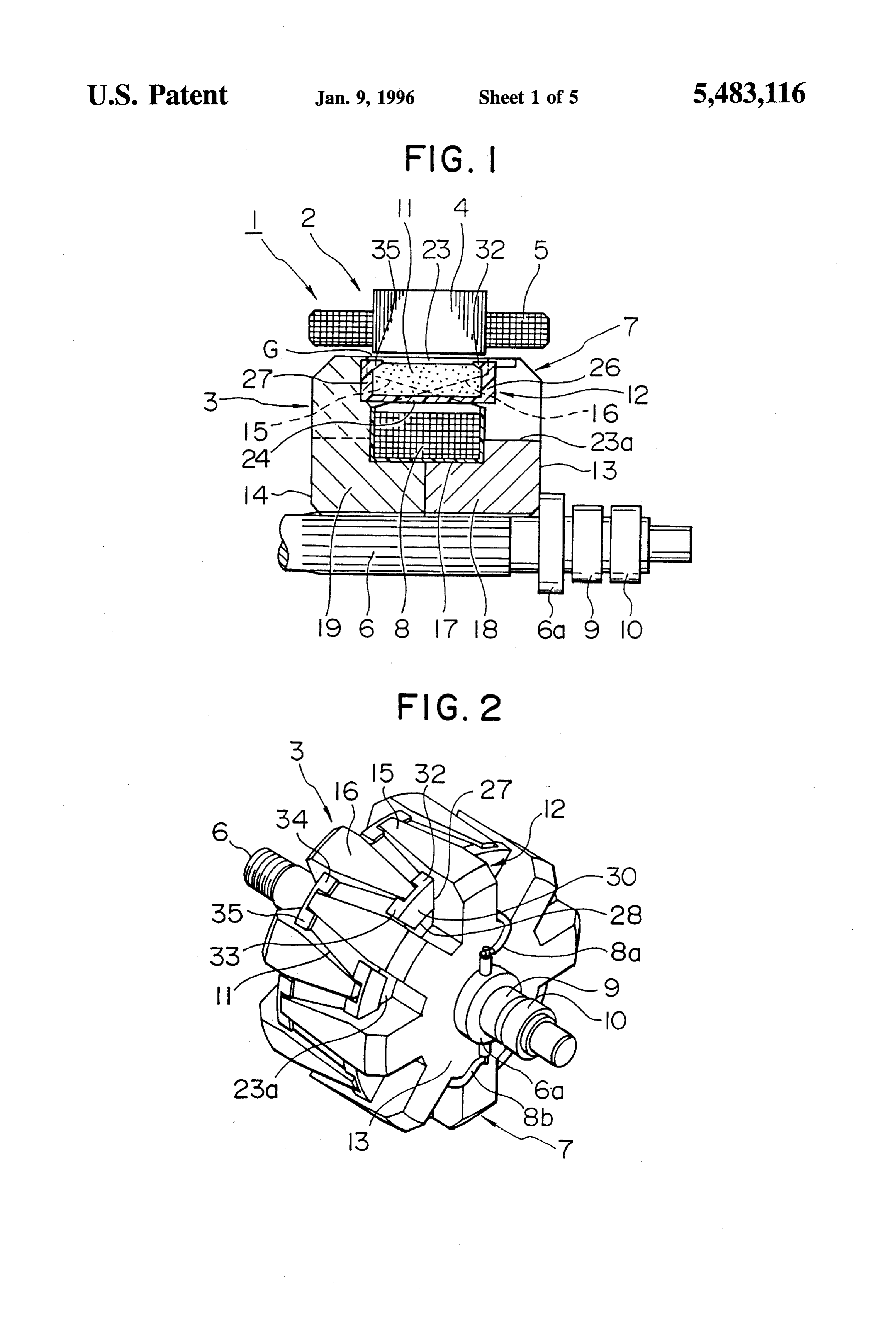
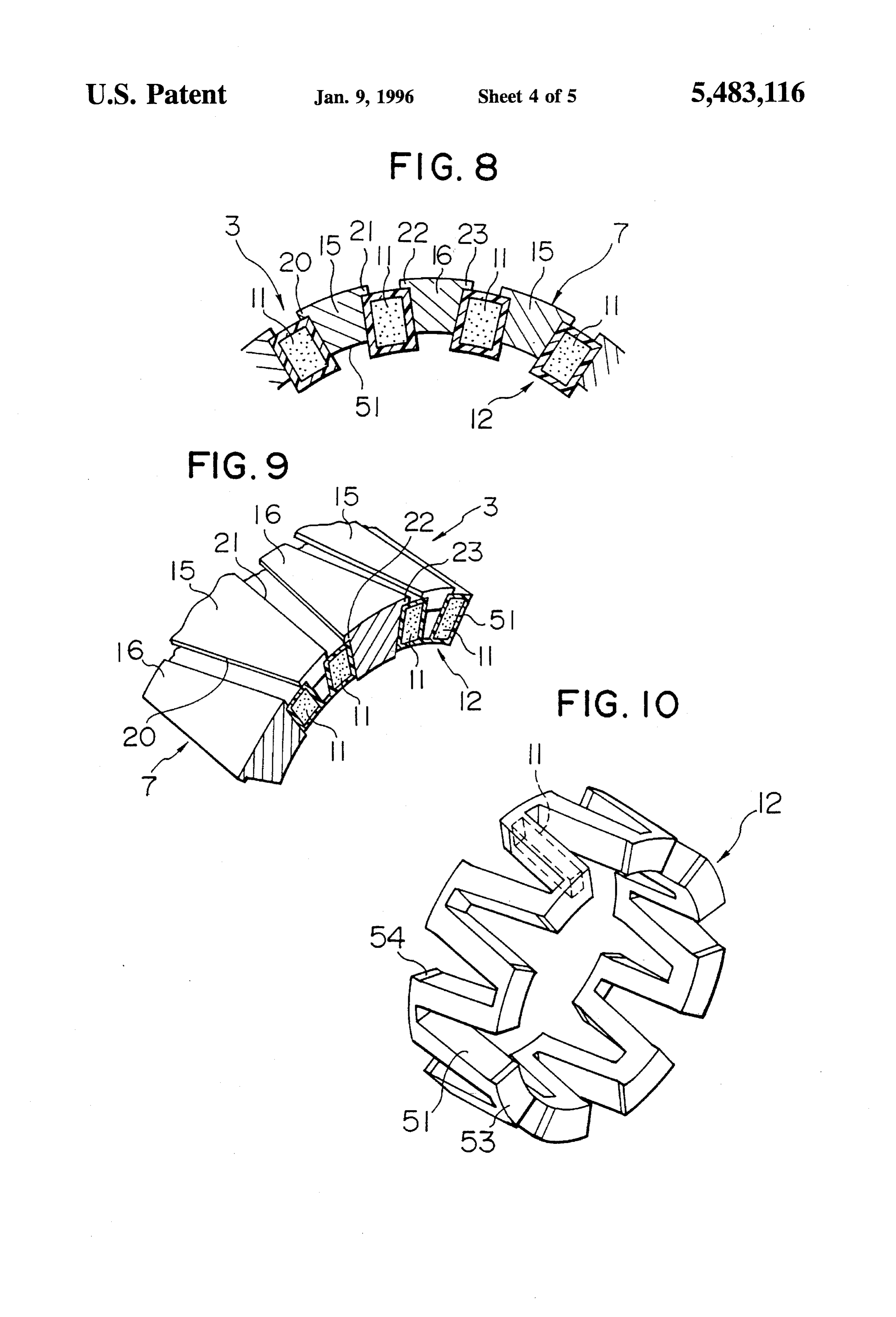
state where the opposed faces facing the side faces of the BRIEF DESCRIPTION OF THE DRAWINGS claw-like magnetic poles are open and the side faces of the permanent magnets contact the side faces of the claw-like 15 Other objects, features and characteristics of the present magnetic poles. invention along with methods of operation and the functions In this arrangement, the assembly of the permanent mag of interrelated parts will become apparent to a person skilled nets to the resin-made magnet holding member can be easily in the art to which the invention pertains from a study of the performed. As the assembly is performed, the magnetic flux following detailed description, the appended claims, and the can be easily passed through the claw-like magnetic poles by 20 attached figures, all of which form a part of this specifica having the permanent magnets contact the side faces of the tion. In the figures:
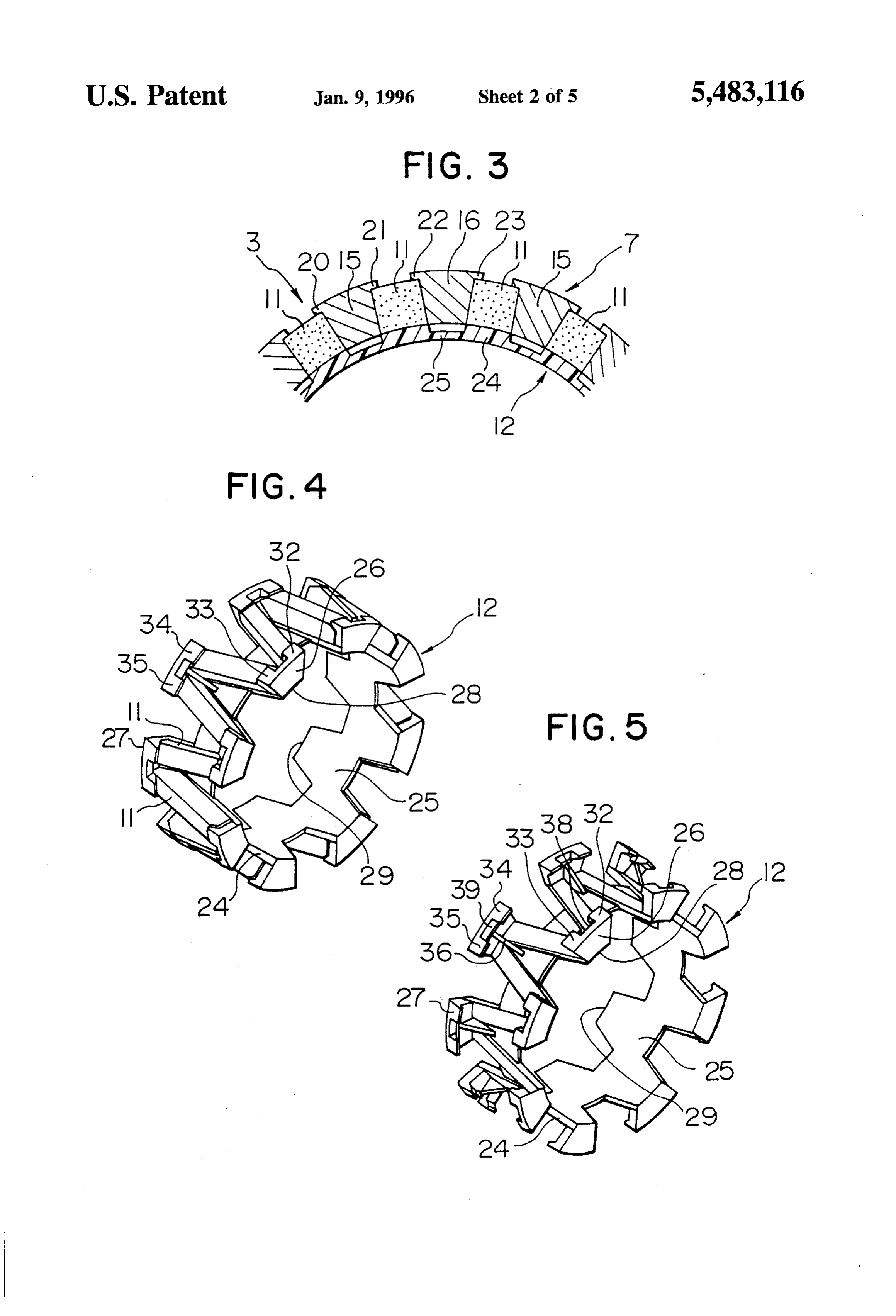
claw-like magnetic poles. FIG. 1 is a sectional view of the main part of the The present invention may also include a plurality of alternating current generator for a vehicle according to a first claw-like magnetic poles that are provided with a flange or embodiment of the present invention;
taper shaped catching parts for suppressing the centrifugal 25 FIG. 2 is a perspective side view of the rotor of the movement of the resin-made magnet holding member. The alternating current generator illustrated in FIG. 1; size of the catching parts is set so that the centrifugal force FIG. 3 is a sectional view of the main part of the rotor of of the permanent magnets compresses the resin-made mag net holding member on the catching parts. The suppression the alternating current generator illustrated in FIG. 1; of the permanent magnets and the resin-made holding mem FIG. 4 is a perspective side view illustrating the state in ber in the centrifugal direction can be performed with 30 which sixteen permanent magnets and a magnet holder are greater precision, and thus resistance to the centrifugal assembled;
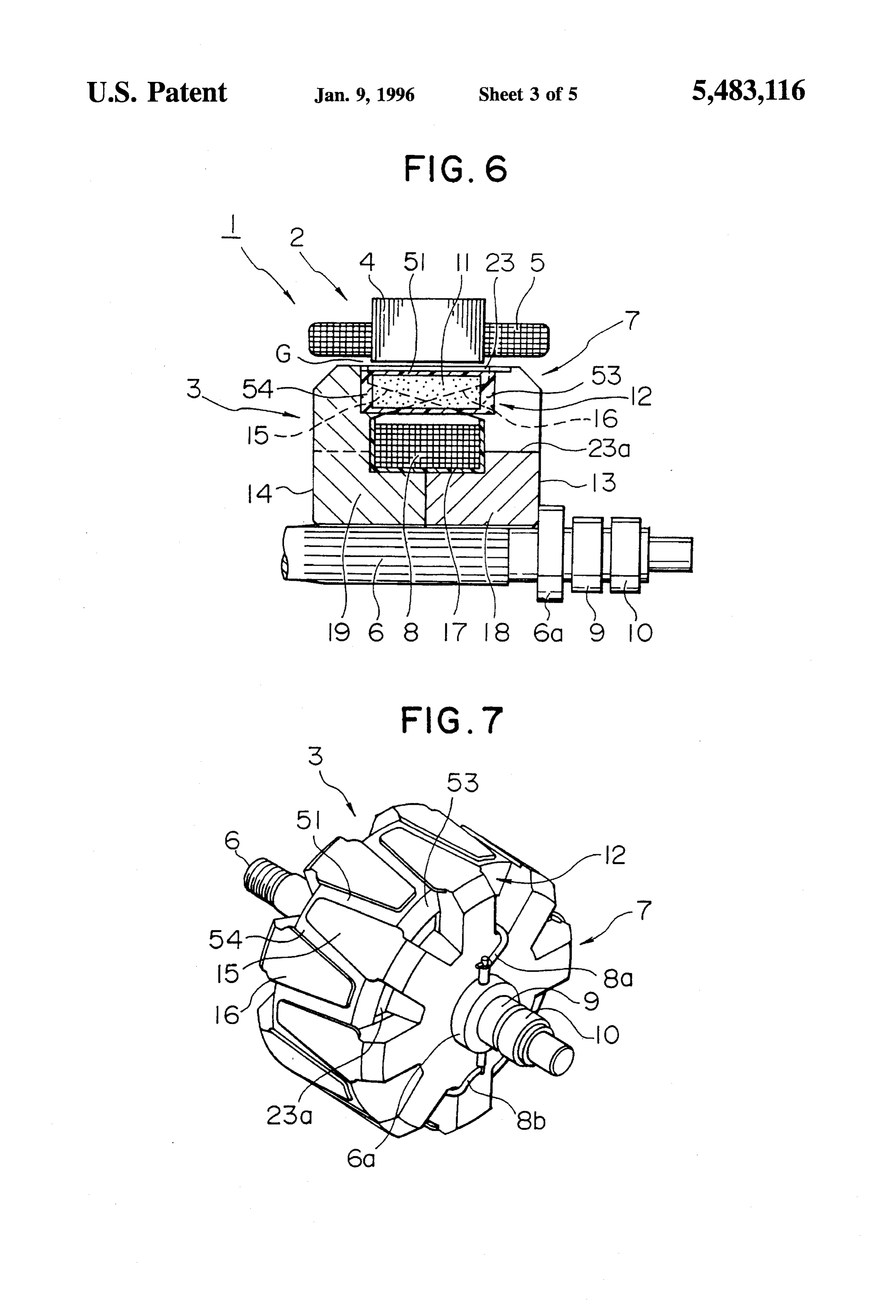
forces acting on the permanent magnets and holding mem FIG. 5 is a perspective side view of a magnet holder; ber can be improved. FIG. 6 is a sectional view of the main part of the The rotating electric machine may be an alternating 35 alternating current generator for a vehicle employed accord current generator. The rotor may have Lundell-type pole ing to a second embodiment of the present invention; cores, which allow the resin-made magnet holding member FIG. 7 is a perspective side view of the rotor of the holding the permanent magnets to intervene suitably, and the alternating current generator illustrated in FIG. 6; power generating efficiency can be improved by the perma FIG. 8 is a sectional view of the main part of the rotor of nent magnets.
40 the alternating current generator illustrated in FIG. 6;
The resin-made magnet holding member does not have to FIG. 9 is a perspective side view of the main part of the have both ends thereof interconnected even though it is rotor of the alternating current generator illustrated in FIG. formed in a circular manner, thus allowing for size differ 8;
ences between the permanent magnets and the resin-made magnet holding member to be easily absorbed. That is, the 45 FIG. 10 is a perspective side view of a magnet holder with resin-made holding member may be formed to have a which sixteen permanent magnets are molded;
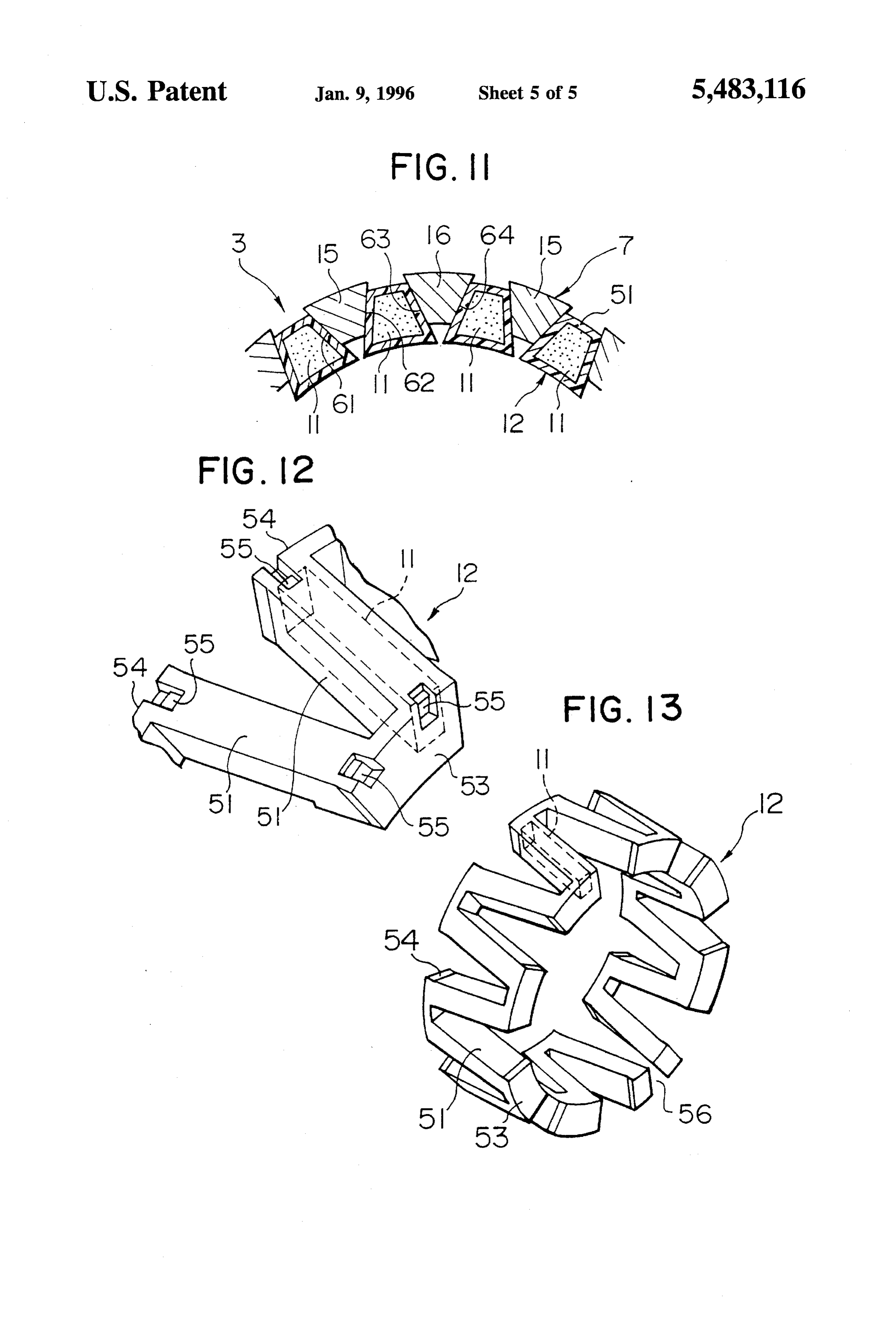
discontinuity therein. FIG. 11 is a sectional view of the main part of the rotor It is also possible for the present invention to include pole of the alternating current generator for a vehicle according cores having a plurality of claw-like magnetic poles formed to a third embodiment of the present invention; on the outer periphery thereof, which are assembled so that 50 FIG. 12 is a magnified view of the main part of the magnet the claw-like magnetic poles engage with each other and holder illustrating the modification where part of the per rotate integrally with a rotatable shaft. The present invention manent magnet is exposed; and may also have a plurality of permanent magnets each of FIG. 13 is a perspective side view illustrating the modi which is disposed between two adjacent claw-like magnetic fication where a part of the magnet holder is formed so as to poles of the pole cores and magnetized in the direction that 55 be discontinuous.
diminishes the magnetic flux leakage between the claw-like DETAILED DESCRIPTION OF THE magnet poles. Further, a resin-made holding member may be PRESENTLY PREFERRED EXEMPLARY fit between side faces of the two adjacent claw-like magnetic EMBODIMENTS poles to hold the permanent magnets. The resin-made mag net holding member is preferably formed so that it zig-zags 60 The rotor of a rotating electric machine according to the in a complete circle, making repeated V-shaped turns. present invention will now be described with reference to According to the present invention, as a plurality of the attached figures.
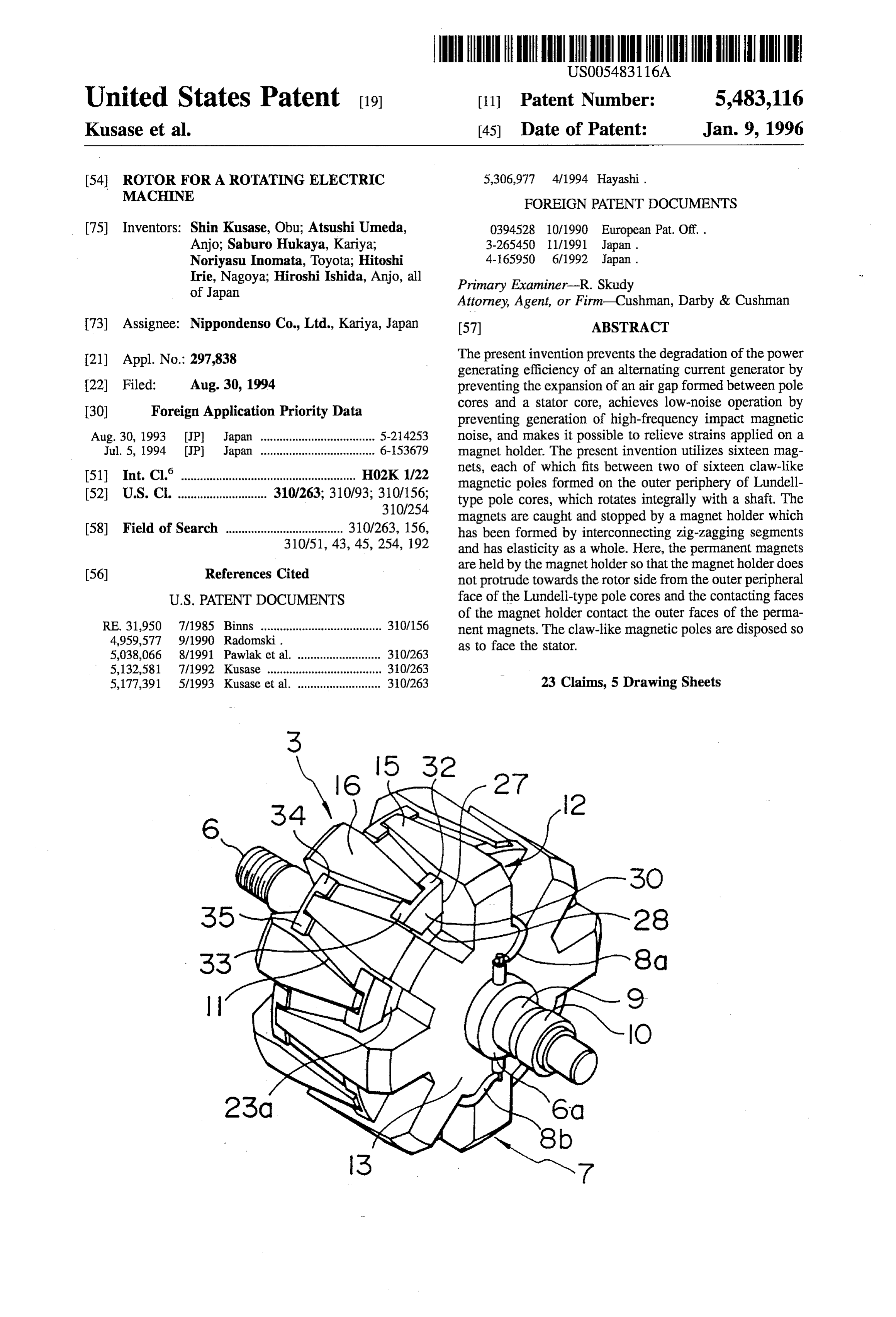
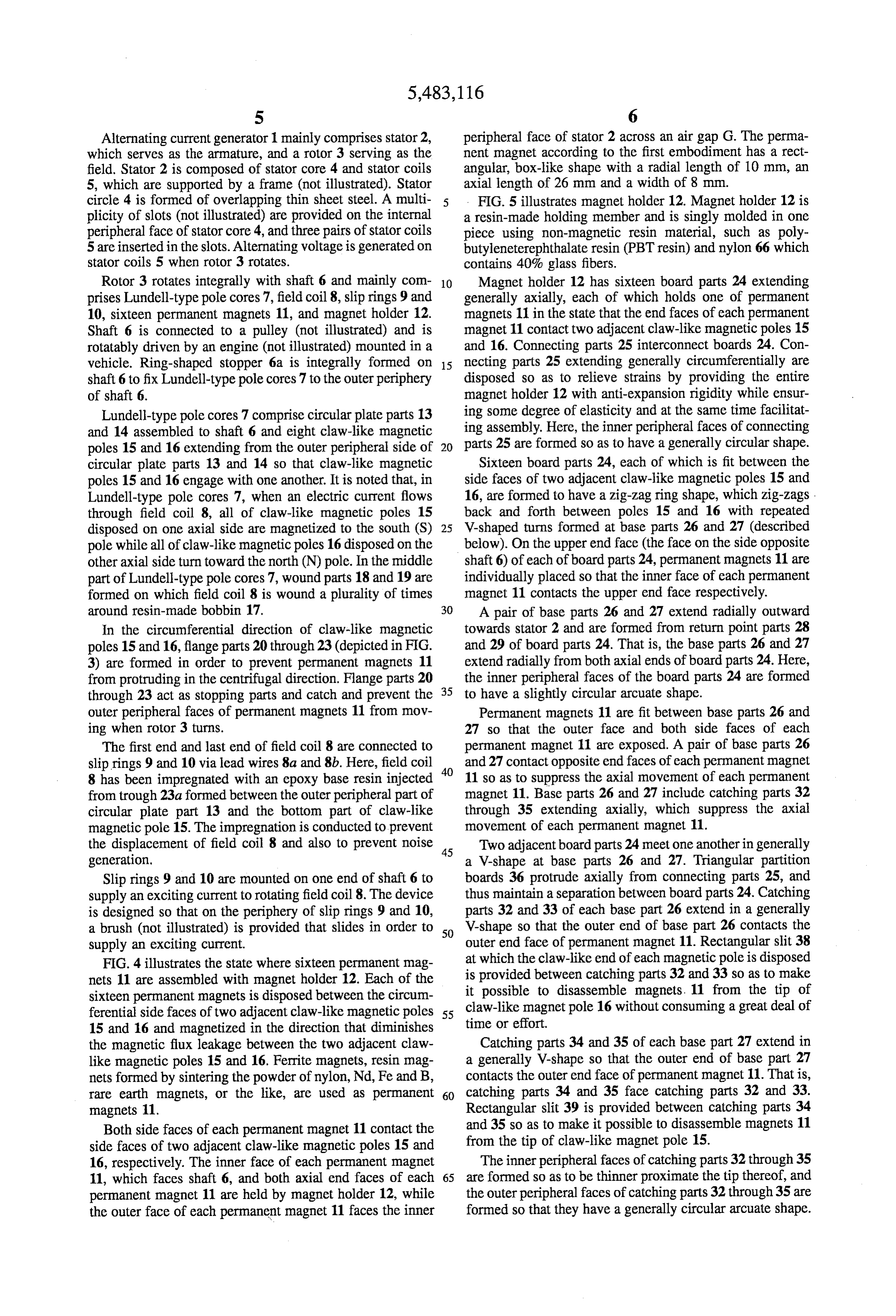
permanent magnets are held by a resin-made magnet holding FIGS. 1 through 5 illustrate the first embodiment of the member fit between the side faces of each of two adjacent present invention. FIG. 1 illustrates the main part of an claw-like magnet poles of Lundell-type pole cores, the gap 65 alternating current generator for a vehicle, while FIGS. 2 between the outer peripheral face of the rotor and the inner and 3 illustrate a rotor of an alternating current generator, as peripheral face of the stator, i.e., the air gap, does not a rotating electric machine.
Page 9
Alternating current generator 1 mainly comprises stator 2, peripheral face of stator 2 across an air gap G. The perma which serves as the armature, and a rotor 3 serving as the nent magnet according to the first embodiment has a rect field. Stator 2 is composed of stator core 4 and stator coils angular, box-like shape with a radial length of 10 mm, an 5, which are supported by a frame (not illustrated). Stator axial length of 26 mm and a width of 8 mm. circle 4 is formed of overlapping thin sheet steel. A multi FIG. 5 illustrates magnet holder 12. Magnet holder 12 is plicity of slots (not illustrated) are provided on the internal a resin-made holding member and is singly molded in one peripheral face of stator core 4, and three pairs of stator coils piece using non-magnetic resin material, such as poly 5 are inserted in the slots. Alternating voltage is generated on butyleneterephthalate resin (PBT resin) and nylon 66 which stator coils 5 when rotor 3 rotates. contains 40% glass fibers. Rotor 3 rotates integrally with shaft 6 and mainly com 10 Magnet holder 12 has sixteen board parts 24 extending prises Lundell-type pole cores 7, field coil 8, slip rings 9 and generally axially, each of which holds one of permanent 10, sixteen permanent magnets 11, and magnet holder 12. magnets 11 in the state that the end faces of each permanent Shaft 6 is connected to a pulley (not illustrated) and is magnet 11 contact two adjacent claw-like magnetic poles 15 rotatably driven by an engine (not illustrated) mounted in a and 16. Connecting parts 25 interconnect boards 24. Con vehicle. Ring-shaped stopper 6a is integrally formed on 15 necting parts 25 extending generally circumferentially are shaft 6 to fix Lundell-type pole cores 7 to the outer periphery disposed so as to relieve strains by providing the entire of shaft 6. magnet holder 12 with anti-expansion rigidity while ensur Lundell-type pole cores 7 comprise circular plate parts 13 ing some degree of elasticity and at the same time facilitat and 14 assembled to shaft 6 and eight claw-like magnetic ing assembly. Here, the inner peripheral faces of connecting poles 15 and 16 extending from the outer peripheral side of 20 parts 25 are formed so as to have a generally circular shape. circular plate parts 13 and 14 so that claw-like magnetic Sixteen board parts 24, each of which is fit between the poles 15 and 16 engage with one another. It is noted that, in side faces of two adjacent claw-like magnetic poles 15 and Lundell-type pole cores 7, when an electric current flows 16, are formed to have a Zig-Zag ring shape, which zig-zags. through field coil 8, all of claw-like magnetic poles 15 back and forth between poles 15 and 16 with repeated disposed on one axial side are magnetized to the south (S) 25 V-shaped turns formed at base parts 26 and 27 (described pole while all of claw-like magnetic poles 16 disposed on the below). On the upper end face (the face on the side opposite other axial side turn toward the north (N) pole. In the middle shaft 6) of each of board parts 24, permanent magnets 11 are part of Lundell-type pole cores 7, wound parts 18 and 19 are individually placed so that the inner face of each permanent formed on which field coil 8 is wound a plurality of times magnet 11 contacts the upper end face respectively. around resin-made bobbin 17. A pair of base parts 26 and 27 extend radially outward
In the circumferential direction of claw-like magnetic towards stator 2 and are formed from return point parts 28 poles 15 and 16, flange parts 20 through 23 (depicted in FIG. and 29 of board parts 24. That is, the base parts 26 and 27 3) are formed in order to prevent permanent magnets 11 extend radially from both axial ends of board parts 24. Here, from protruding in the centrifugal direction. Flange parts 20 the inner peripheral faces of the board parts 24 are formed through 23 act as stopping parts and catch and prevent the 35 to have a slightly circular arcuate shape. outer peripheral faces of permanent magnets 11 from mov Permanent magnets 11 are fit between base parts 26 and ing when rotor 3 turns. 27 so that the outer face and both side faces of each The first end and last end of field coil 8 are connected to permanent magnet 11 are exposed. A pair of base parts 26 slip rings 9 and 10 via lead wires 8a and 8b. Here, field coil and 27 contact opposite end faces of each permanent magnet 8 has been impregnated with an epoxy base resin injected 11 so as to suppress the axial movement of each permanent from trough 23a formed between the outer peripheral part of magnet 11. Base parts 26 and 27 include catching parts 32 circular plate part 13 and the bottom part of claw-like through 35 extending axially, which suppress the axial magnetic pole 15. The impregnation is conducted to prevent movement of each permanent magnet 11. the displacement of field coil 8 and also to prevent noise 45 Two adjacent board parts 24 meet one anotheringenerally generation. a V-shape at base parts 26 and 27. Triangular partition Slip rings 9 and 10 are mounted on one end of shaft 6 to boards 36 protrude axially from connecting parts 25, and supply an exciting current to rotating field coil 8. The device thus maintain a separation between board parts 24. Catching is designed so that on the periphery of slip rings 9 and 10, parts 32 and 33 of each base part 26 extend in a generally a brush (not illustrated) is provided that slides in order to 50 V-shape so that the outer end of base part 26 contacts the supply an exciting current. outer end face of permanent magnet 11. Rectangular slit 38 FIG. 4 illustrates the state where sixteen permanent mag at which the claw-like end of each magnetic pole is disposed nets 11 are assembled with magnet holder 12. Each of the is provided between catching parts 32 and 33 so as to make sixteen permanent magnets is disposed between the circum it possible to disassemble magnets. 11 from the tip of ferential side faces of two adjacent claw-like magnetic poles 55 claw-like magnet pole 16 without consuming a great deal of time or effort.
15 and 16 and magnetized in the direction that diminishes the magnetic flux leakage between the two adjacent claw Catching parts 34 and 35 of each base part 27 extend in like magnetic poles 15 and 16. Ferrite magnets, resin mag a generally V-shape so that the outer end of base part 27 nets formed by sintering the powder of nylon, Nd, Fe and B, contacts the outer end face of permanent magnet 11. That is, rare earth magnets, or the like, are used as permanent 60 catching parts 34 and 35 face catching parts 32 and 33. magnets 11. Rectangular slit 39 is provided between catching parts 34 Both side faces of each permanent magnet 11 contact the and 35 so as to make it possible to disassemble magnets 11 side faces of two adjacent claw-like magnetic poles 15 and from the tip of claw-like magnet pole 15. 16, respectively. The inner face of each permanent magnet The inner peripheral faces of catching parts 32 through 35 11, which faces shaft 6, and both axial end faces of each 65 are formed so as to be thinner proximate the tip thereof, and permanent magnet 11 are held by magnet holder 12, while the outer peripheral faces of catching parts 32 through 35 are the outer face of each permanent magnet 11 faces the inner formed so that they have a generally circular arcuate shape.
Page 10
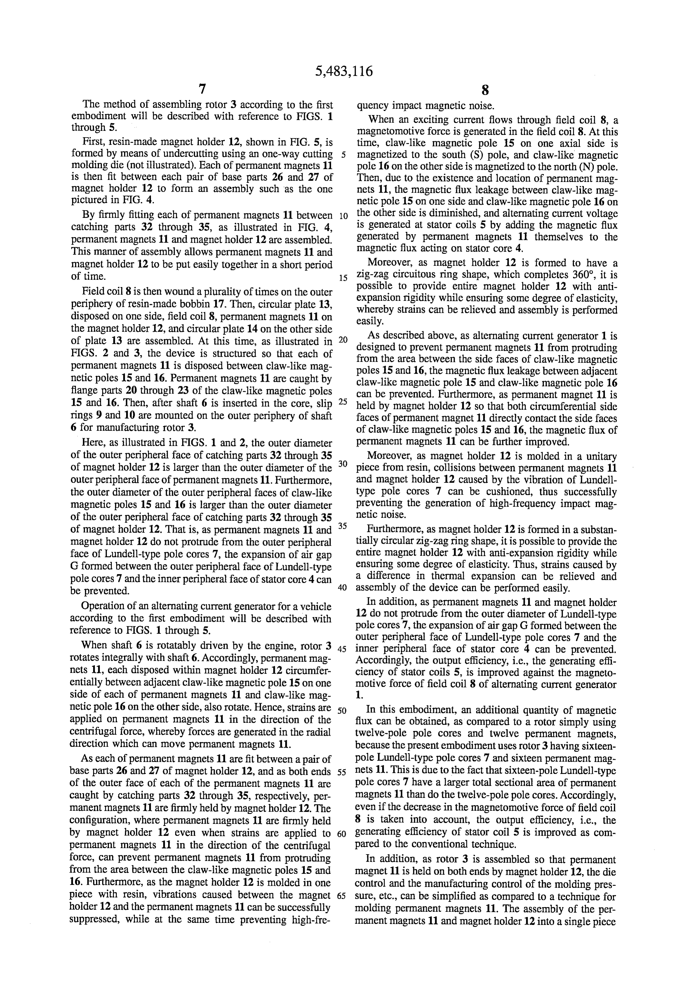
The method of assembling rotor 3 according to the first quency impact magnetic noise.
embodiment will be described with reference to FIGS. 1 When an exciting current flows through field coil 8, a through 5. magnetomotive force is generated in the field coil 8. At this First, resin-made magnet holder 12, shown in FIG. 5, is time, claw-like magnetic pole 15 on one axial side is formed by means of undercutting using an one-way cutting magnetized to the south (S) pole, and claw-like magnetic molding die (not illustrated). Each of permanent magnets 11 pole 16 on the other side is magnetized to the north (N) pole. is then fit between each pair of base parts 26 and 27 of Then, due to the existence and location of permanent mag magnet holder 12 to form an assembly such as the one nets 11, the magnetic flux leakage between claw-like mag pictured in FIG. 4. netic pole 15 on one side and claw-like magnetic pole 16 on By firmly fitting each of permanent magnets 11 between 10 the other side is diminished, and alternating current voltage catching parts 32 through 35, as illustrated in FIG. 4, is generated at stator coils 5 by adding the magnetic flux permanent magnets 11 and magnet holder 12 are assembled. generated by permanent magnets 11 themselves to the This manner of assembly allows permanent magnets 11 and magnetic flux acting on stator core 4.
magnet holder 12 to be put easily together in a short period Moreover, as magnet holder 12 is formed to have a of time. 15 zig-zag circuitous ring shape, which completes 360, it is possible to provide entire magnet holder 12 with anti
Field coil 8 is then wound a plurality of times on the outer expansion periphery of resin-made bobbin 17. Then, circular plate 13, whereby strains rigidity while ensuring some degree of elasticity, disposed on one side, field coil 8, permanent magnets 11 on can be relieved and assembly is performed easily.
the magnet holder 12, and circular plate 14 on the other side As described above, as alternating current generator 1 is of plate 13 are assembled. At this time, as illustrated in 20 designed to prevent permanent magnets 11 from protruding FIGS. 2 and 3, the device is structured so that each of from the area between the side faces of claw-like magnetic permanent magnets 11 is disposed between claw-like mag poles 15 and 16, the magnetic flux leakage between adjacent netic poles 15 and 16. Permanent magnets 11 are caught by claw-like magnetic pole 15 and claw-like magnetic pole 16 flange parts 20 through 23 of the claw-like magnetic poles can be prevented. Furthermore, as permanent magnet 11 is 15 and 16. Then, after shaft 6 is inserted in the core, slip 25 held by magnet holder 12 so that both circumferential side rings 9 and 10 are mounted on the outer periphery of shaft faces of permanent magnet 11 directly contact the side faces 6 for manufacturing rotor 3. of claw-like magnetic poles 15 and 16, the magnetic flux of Here, as illustrated in FIGS. 1 and 2, the outer diameter permanent magnets 11 can be further improved. of the outer peripheral face of catching parts 32 through 35 30 Moreover, as magnet holder 12 is molded in a unitary of magnet holder 12 is larger than the outer diameter of the piece from resin, collisions between permanent magnets 11 outer peripheral face of permanent magnets 11. Furthermore, and magnet holder 12 caused by the vibration of Lundell the outer diameter of the outer peripheral faces of claw-like type pole cores 7 can be cushioned, thus successfully magnetic poles 15 and 16 is larger than the outer diameter preventing the generation of high-frequency impact mag of the outer peripheral face of catching parts 32 through 35 35 netic noise.
of magnet holder 12. That is, as permanent magnets 11 and Furthermore, as magnet holder 12 is formed in a substan magnet holder 12 do not protrude from the outer peripheral tially circular zig-zag ring shape, it is possible to provide the face of Lundell-type pole cores 7, the expansion of air gap entire magnet holder 12 with anti-expansion rigidity while G formed between the outer peripheral face of Lundell-type ensuring some degree of elasticity. Thus, strains caused by pole cores 7 and the inner peripheral face of stator core 4 can a difference in thermal expansion can be relieved and be prevented. assembly of the device can be performed easily. Operation of an alternating current generator for a vehicle In addition, as permanent magnets 11 and magnet holder according to the first embodiment will be described with 12 do not protrude from the outer diameter of Lundell-type reference to FIGS. 1 through 5. pole cores 7, the expansion of air gap G formed between the outer peripheral face of Lundell-type pole cores 7 and the
When shaft 6 is rotatably driven by the engine, rotor 3 45 inner peripheral face of stator core 4 can be prevented. rotates integrally with shaft 6. Accordingly, permanent mag Accordingly, the output efficiency, i.e., the generating effi nets 11, each disposed within magnet holder 12 circumfer ciency of stator coils 5, is improved against the magneto entially between adjacent claw-like magnetic pole 15 on one motive force of field coil 8 of alternating current generator side of each of permanent magnets 11 and claw-like mag 1.
netic pole 16 on the other side, also rotate. Hence, strains are 50 In this embodiment, an additional quantity of magnetic applied on permanent magnets 11 in the direction of the flux can be obtained, as compared to a rotor simply using centrifugal force, whereby forces are generated in the radial twelve-pole pole cores and twelve permanent magnets, direction which can move permanent magnets 11. because the present embodiment uses rotor 3 having sixteen As each of permanent magnets 11 are fit between a pair of pole Lundell-type pole cores 7 and sixteen permanent mag base parts 26 and 27 of magnet holder 12, and as both ends 55 nets 11. This is due to the fact that sixteen-pole Lundell-type of the outer face of each of the permanent magnets 11 are pole cores 7 have a larger total sectional area of permanent caught by catching parts 32 through 35, respectively, per magnets 11 than do the twelve-pole pole cores. Accordingly, manent magnets 11 are firmly held by magnet holder 12. The even if the decrease in the magnetomotive force of field coil configuration, where permanent magnets 11 are firmly held 8 is taken into account, the output efficiency, i.e., the by magnet holder 12 even when strains are applied to 60 generating efficiency of stator coil 5 is improved as com permanent magnets 11 in the direction of the centrifugal pared to the conventional technique. force, can prevent permanent magnets 11 from protruding In addition, as rotor 3 is assembled so that permanent from the area between the claw-like magnetic poles 15 and magnet 11 is held on both ends by magnet holder 12, the die 16. Furthermore, as the magnet holder 12 is molded in one control and the manufacturing control of the molding pres piece with resin, vibrations caused between the magnet 65 sure, etc., can be simplified as compared to a technique for holder 12 and the permanent magnets 11 can be successfully molding permanent magnets 11. The assembly of the per suppressed, while at the same time preventing high-fre manent magnets 11 and magnet holder 12 into a single piece
Page 11
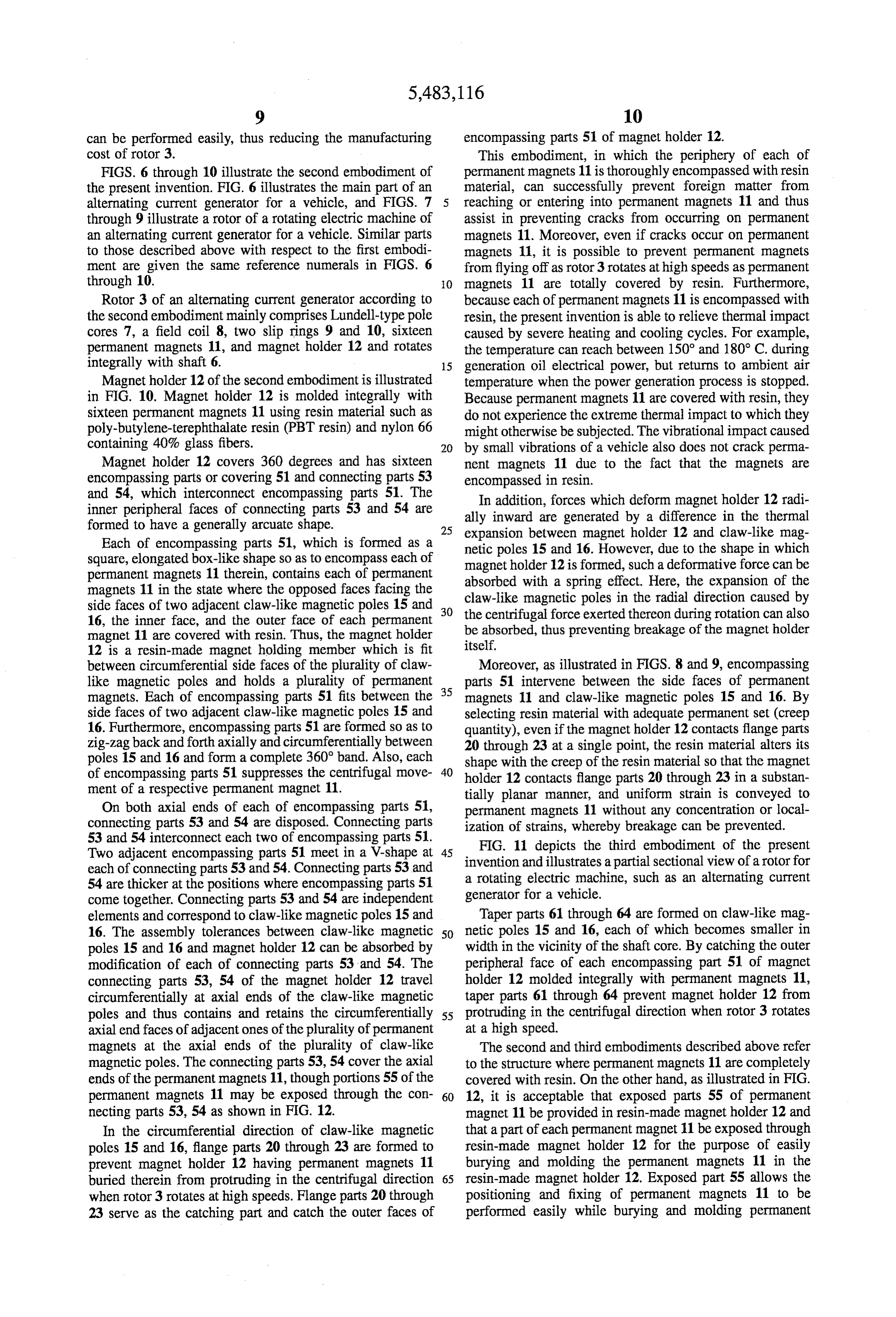
can be performed easily, thus reducing the manufacturing encompassing parts 51 of magnet holder 12. cost of rotor 3. This embodiment, in which the periphery of each of FIGS. 6 through 10 illustrate the second embodiment of permanent magnets 11 is thoroughly encompassed with resin the present invention. FIG. 6 illustrates the main part of an material, can successfully prevent foreign matter from alternating current generator for a vehicle, and FIGS. 7 reaching or entering into permanent magnets 11 and thus through 9 illustrate a rotor of a rotating electric machine of assist in preventing cracks from occurring on permanent an alternating current generator for a vehicle. Similar parts magnets 11. Moreover, even if cracks occur on permanent to those described above with respect to the first embodi magnets 11, it is possible to prevent permanent magnets ment are given the same reference numerals in FIGS. 6 from flying off as rotor 3 rotates at high speeds as permanent through 10. O magnets 11 are totally covered by resin. Furthermore, Rotor 3 of an alternating current generator according to because each of permanent magnets 11 is encompassed with the second embodiment mainly comprises Lundell-type pole resin, the present invention is able to relieve thermal impact cores 7, a field coil 8, two slip rings 9 and 10, sixteen caused by severe heating and cooling cycles. For example, permanent magnets 11, and magnet holder 12 and rotates the temperature can reach between 150 and 180° C. during integrally with shaft 6. 15 generation oil electrical power, but returns to ambient air Magnet holder 12 of the second embodiment is illustrated temperature when the power generation process is stopped. in FIG. 10. Magnet holder 12 is molded integrally with Because permanent magnets 11 are covered with resin, they sixteen permanent magnets 11 using resin material such as do not experience the extreme thermal impact to which they poly-butylene-terephthalate resin (PBT resin) and nylon 66 might otherwise be subjected. The vibrational impact caused containing 40% glass fibers. 20 by small vibrations of a vehicle also does not crack perma Magnet holder 12 covers 360 degrees and has sixteen nent magnets 11 due to the fact that the magnets are encompassing parts or covering 51 and connecting parts 53 encompassed in resin.
and 54, which interconnect encompassing parts 51. The inner peripheral faces of connecting parts 53 and 54 are allyIn inward addition, forces which deform magnet holder 12 radi are generated by a difference in the thermal formed to have a generally arcuate shape. 25 expansion between magnet holder 12 and claw-like mag Each of encompassing parts 51, which is formed as a netic poles 15 and 16. However, due to the shape in which square, elongated box-like shape so as to encompass each of magnet holder 12 is formed, such a deformative force can be permanent magnets 11 therein, contains each of permanent absorbed with a spring effect. Here, the expansion of the magnets 11 in the state where the opposed faces facing the claw-like magnetic poles in the radial direction caused by side faces of two adjacent claw-like magnetic poles 15 and 30 the centrifugal force exerted thereon during rotation can also 16, the inner face, and the outer face of each permanent be absorbed, thus preventing breakage of the magnet holder magnet 11 are covered with resin. Thus, the magnet holder itself.
12 is a resin-made magnet holding member which is fit between circumferential side faces of the plurality of claw Moreover, as illustrated in FIGS. 8 and 9, encompassing like magnetic poles and holds a plurality of permanent 35 parts 51 intervene between the side faces of permanent magnets. Each of encompassing parts 51 fits between the magnets 11 and claw-like magnetic poles 15 and 16. By side faces of two adjacent claw-like magnetic poles 15 and selecting resin material with adequate permanent set (creep 16. Furthermore, encompassing parts 51 are formed so as to quantity), even if the magnet holder 12 contacts flange parts zig-zag back and forth axially and circumferentially between 20 through 23 at a single point, the resin material alters its poles 15 and 16 and form a complete 360° band. Also, each shape with the creep of the resin material so that the magnet of encompassing parts 51 suppresses the centrifugal move 40 holder 12 contacts flange parts 20 through 23 in a substan ment of a respective permanent magnet 11. tially planar manner, and uniform strain is conveyed to On both axial ends of each of encompassing parts 51, permanent magnets 11 without any concentration or local connecting parts 53 and 54 are disposed. Connecting parts ization of strains, whereby breakage can be prevented. 53 and 54 interconnect each two of encompassing parts 51. FIG. 11 depicts the third embodiment of the present Two adjacent encompassing parts 51 meet in a V-shape at 45 invention and illustrates apartial sectional view of a rotor for each of connecting parts 53 and 54. Connecting parts 53 and 54 are thicker at the positions where encompassing parts 51 a rotating electric machine, such as an alternating current come together. Connecting parts 53 and 54 are independent generator for a vehicle.
elements and correspond to claw-like magnetic poles 15 and Taper parts 61 through 64 are formed on claw-like mag 16. The assembly tolerances between claw-like magnetic 50 netic poles 15 and 16, each of which becomes smaller in poles 15 and 16 and magnet holder 12 can be absorbed by width in the vicinity of the shaft core. By catching the outer modification of each of connecting parts 53 and 54. The peripheral face of each encompassing part 51 of magnet connecting parts 53, 54 of the magnet holder 12 travel holder 12 molded integrally with permanent magnets 11, circumferentially at axial ends of the claw-like magnetic taper parts 61 through 64 prevent magnet holder 12 from poles and thus contains and retains the circumferentially 55 protruding in the centrifugal direction when rotor 3 rotates axial end faces of adjacent ones of the plurality of permanent at a high speed.
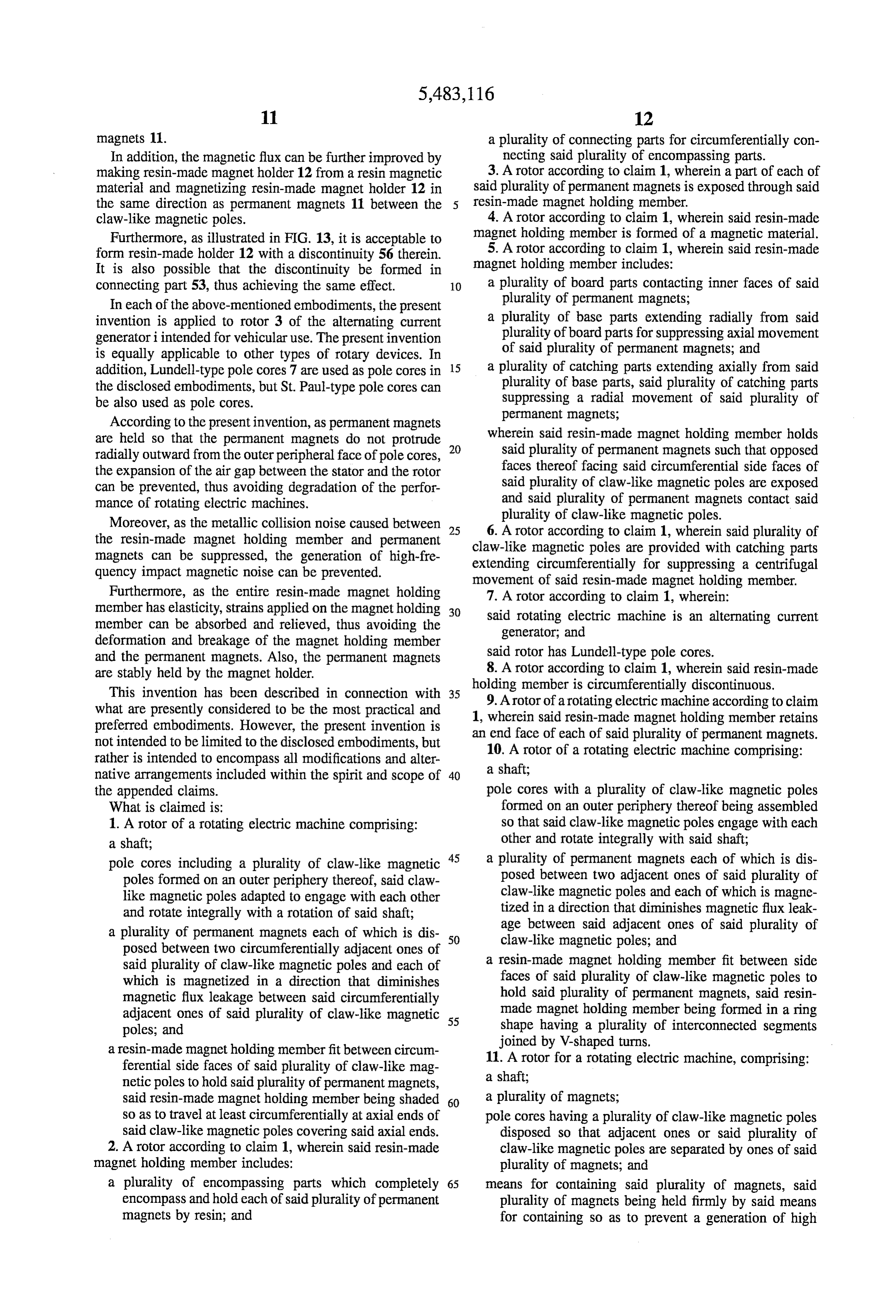
magnets at the axial ends of the plurality of claw-like The second and third embodiments described above refer magnetic poles. The connecting parts 53, 54 cover the axial to the structure where permanent magnets 11 are completely ends of the permanent magnets 11, though portions 55 of the covered with resin. On the other hand, as illustrated in FIG. permanent magnets 11 may be exposed through the con 60 12, it is acceptable that exposed parts 55 of permanent necting parts 53, 54 as shown in FIG. 12. magnet 11 be provided in resin-made magnet holder 12 and In the circumferential direction of claw-like magnetic that a part of each permanent magnet 11 be exposed through poles 15 and 16, flange parts 20 through 23 are formed to resin-made magnet holder 12 for the purpose of easily prevent magnet holder 12 having permanent magnets 11 burying and molding the permanent magnets 11 in the buried therein from protruding in the centrifugal direction 65 resin-made magnet holder 12. Exposed part 55 allows the when rotor 3 rotates at high speeds. Flange parts 20 through positioning and fixing of permanent magnets 11 to be 23 serve as the catching part and catch the outer faces of performed easily while burying and molding permanent
Page 12
magnets 11. a plurality of connecting parts for circumferentially con In addition, the magnetic flux can be further improved by necting said plurality of encompassing parts. making resin-made magnet holder 12 from a resin magnetic 3. A rotor according to claim 1, wherein a part of each of material and magnetizing resin-made magnet holder 12 in said plurality of permanent magnets is exposed through said the same direction as permanent magnets 11 between the 5 resin-made magnet holding member.
claw-like magnetic poles. 4. A rotor according to claim 1, wherein said resin-made Furthermore, as illustrated in FIG. 13, it is acceptable to magnet holding member is formed of a magnetic material. form resin-made holder 12 with a discontinuity 56 therein. 5. A rotor according to claim 1, wherein said resin-made It is also possible that the discontinuity be formed in magnet holding member includes:
connecting part 53, thus achieving the same effect. 10 a plurality of board parts contacting inner faces of said In each of the above-mentioned embodiments, the present plurality of permanent magnets; invention is applied to rotor 3 of the alternating current a plurality of base parts extending radially from said generatori intended for vehicular use. The present invention plurality of board parts for suppressing axial movement is equally applicable to other types of rotary devices. In of said plurality of permanent magnets; and addition, Lundell-type pole cores 7 are used as pole cores in 15 a plurality of catching parts extending axially from said the disclosed embodiments, but St. Paul-type pole cores can plurality of base parts, said plurality of catching parts be also used as pole cores. suppressing a radial movement of said plurality of According to the present invention, as permanent magnets permanent magnets;
are held so that the permanent magnets do not protrude 20 wherein said resin-made magnet holding member holds radially outward from the outer peripheral face of pole cores, said plurality of permanent magnets such that opposed the expansion of the air gap between the stator and the rotor faces thereof facing said circumferential side faces of can be prevented, thus avoiding degradation of the perfor said plurality of claw-like magnetic poles are exposed mance of rotating electric machines. and said plurality of permanent magnets contact said plurality
Moreover, as the metallic collision noise caused between 25 6. A rotor according of claw-like magnetic poles. the resin-made magnet holding member and permanent to claim 1, wherein said plurality of magnets can be suppressed, the generation of high-fre claw-like magnetic poles are provided with catching parts quency impact magnetic noise can be prevented. extending circumferentially for suppressing a centrifugal movement of said resin-made magnet holding member.
Furthermore, as the entire resin-made magnet holding 7. A rotor according to claim 1, wherein: member has elasticity, strains applied on the magnet holding 30 said rotating electric machine is an alternating current member can be absorbed and relieved, thus avoiding the generator, and deformation and breakage of the magnet holding member and the permanent magnets. Also, the permanent magnets said rotor has Lundell-type pole cores. are stably held by the magnet holder. 8. A rotor according to claim 1, wherein said resin-made This invention has been described in connection with 35 holding member is circumferentially discontinuous. what are presently considered to be the most practical and 9. A rotor of a rotating electric machine according to claim preferred embodiments. However, the present invention is 1, wherein said resin-made magnet holding member retains not intended to be limited to the disclosed embodiments, but an end face of each of said plurality of permanent magnets. rather is intended to encompass all modifications and alter 10. A rotor of a rotating electric machine comprising: native arrangements included within the spirit and scope of 40 a shaft;
the appended claims. pole cores with a plurality of claw-like magnetic poles What is claimed is: formed on an outer periphery thereof being assembled 1. A rotor of a rotating electric machine comprising: so that said claw-like magnetic poles engage with each a shaft; other and rotate integrally with said shaft; pole cores including a plurality of claw-like magnetic 45 a plurality of permanent magnets each of which is dis poles formed on an outer periphery thereof, said claw posed between two adjacent ones of said plurality of like magnetic poles adapted to engage with each other claw-like magnetic poles and each of which is magne and rotate integrally with a rotation of said shaft; tized in a direction that diminishes magnetic flux leak a plurality of permanent magnets each of which is dis 50 age between said adjacent ones of said plurality of posed between two circumferentially adjacent ones of claw-like magnetic poles; and said plurality of claw-like magnetic poles and each of a resin-made magnet holding member fit between side which is magnetized in a direction that diminishes faces of said plurality of claw-like magnetic poles to magnetic flux leakage between said circumferentially hold said plurality of permanent magnets, said resin adjacent ones of said plurality of claw-like magnetic 55 made magnet holding member being formed in a ring poles; and shape having a plurality of interconnected segments a resin-made magnet holding member fit between circum joined by V-shaped turns.
ferential side faces of said plurality of claw-like mag 11. A rotor for a rotating electric machine, comprising: netic poles to hold said plurality of permanent magnets, a shaft;
said resin-made magnet holding member being shaded 60 a plurality of magnets;
so as to travel at least circumferentially at axial ends of pole cores having a plurality of claw-like magnetic poles said claw-like magnetic poles covering said axial ends. disposed so that adjacent ones or said plurality of 2. A rotor according to claim 1, wherein said resin-made claw-like magnetic poles are separated by ones of said magnet holding member includes: plurality of magnets; and a plurality of encompassing parts which completely 65 means for containing said plurality of magnets, said encompass and hold each of said plurality of permanent plurality of magnets being held firmly by said means magnets by resin; and for containing so as to prevent a generation of high
Page 13
frequency impact magnetic noise, said means for con a shaft, taining connecting circumferentially axial ends of adja a plurality of permanent magnets;
cent two of said plurality of magnets at each axial end pole cores having a plurality of claw-like magnetic poles of said claw-like magnetic poles. disposed so that adjacent ones of said plurality of 12. A rotor as claimed in claim 11, wherein said plurality claw-like magnetic poles are supply ones of said plu of magnets are permanent magnets. rality of permanent magnets; and 13. A rotor according to claim 12, wherein said means for means for containing said plurality of permanent magnets, containing includes a holding member formed of a resin said plurality of permanent magnets being held firmly material and having an outermost surface radially inward of by said means for containing so as to prevent a gen said plurality of claw-like magnetic poles. 10 eration of high frequency impact magnetic noise, said 14. A rotor according to claim 13, wherein said holding means for containing including means for covering and member is a substantially circular band including a plurality retaining an end portion of each of said plurality of of interconnected segments, a number of said plurality of permanent magnets at axial ends of each of said plu interconnected segments being equal to a number of said rality of claw-like magnetic poles, said means for plurality of magnets. 15 containing including a holding member formed of a 15. A rotor according to claim 14, wherein said substan resin material and having an outermost surface radially tially circular band of said holding member is discontinuous. inward of said plurality of claw-like magnetic poles, 16. A rotor for a rotating electric machine according to said holding member completely covering said plural claim 11, wherein said means for containing including ity of permanent magnets.
means for retaining an end face of each of said plurality of 20 21. A rotor and a stator for use in an alternating current magnets at axial ends of each of said plurality of claw-like generator, said rotor comprising: magnetic poles. a rotatable shaft;
17. A rotor according to claim 13, wherein said holding pole cores having a plurality of claw-like magnetic poles, member at least partially covers said plurality of magnets. said plurality of claw-like magnetic poles being rotat 18. A rotor for a rotating electric machine comprising: 25 able with said rotatable shaft; a shaft; a plurality of permanent magnets, one of said plurality of a plurality of permanent magnets; magnets being disposed between adjacent ones of said pole cores having a plurality of claw-like magnetic poles plurality of claw-like magnetic poles; and disposed so that adjacent ones of said plurality of 30 means for holding said plurality of permanent magnets in claw-like magnetic poles are separated by ones of said a position between said plurality of claw-like magnetic plurality of permanent magnets; and poles, said means for holding being formed of a resin means for containing said plurality of permanent magnets, material and comprising:
said plurality of permanent magnets being held firmly a plurality of connecting portions which hold end faces by said means for containing so as to prevent a gen 35 of said plurality of magnets, and eration of high frequency impact magnetic noise, said a plurality of interconnecting members that intercon means for containing including means for covering and nect said plurality of connecting portions circumfer retaining an end portion of each of said plurality of entially covering axial ends of said plurality of permanent magnets at axial ends of each of said plu claw-like magnetic poles, a number of said plurality rality of claw-like magnetic poles, said means for of interconnecting members equalling a number of containing including: said plurality of magnets; and a holding member formed of a resin material and said stator comprising:
having an outermost surface radially inward of said a stator core; and plurality of claw-like magnetic poles; a plurality of stator coils; said stator being separated a plurality of connecting portions; and 45 from said plurality of claw-like magnetic poles by an a plurality of board portions connecting said connecting airspace having a predetermined size which does not portions; change during rotation of said rotor. wherein said plurality of permanent magnets are disposed 22. A rotor and a stator for use in an alternating generator on said plurality of board portions, and said plurality of as claimed in claim 21, wherein said holding means is a band permanent magnets have end faces disposed at said 50 covering 360°.
plurality of connecting portions. 23. A rotor and a stator for use in an alternating generator 19. A rotor according to claim 18, wherein two of said as claimed in claim 21, wherein said holding means is plurality of board portions form a V-shaped turn at each of discontinuous.
said plurality of connecting portions.
20. A rotor for a rotating electric machine comprising:
Provenance
- Collection
- Cited prior art
- Original PDF
- patentimages.storage.googleapis.com →
- Filed
- 1994-08-30
- Pages
- 13
- Method
- pdftotext (the PDF's own text layer) + pdftoppm 300dpi page scans
- Source
- Google Patents bibliographic record
- Granted
- 1996-01-09
- Inventors
- Shin Kusase; Atsushi Umeda; Saburo Hukaya; Noriyasu Inomata; Hitoshi Irie; Hiroshi Ishida; NipponDenso Co Ltd
- Transcribed from
- patentimages.storage.googleapis.com →