patent · US5090711
Seal assemblies for internal mixers
25 February 1992
Page 1 — bibliographic record
United States Patent (19) 11 Patent Number: 5,090,711 Becker (45) Date of Patent: Feb. 25, 1992 54). SEAL ASSEMBLIES FOR INTERNAL FOREIGN PATENT DOCUMENTS
MIXERS
348765 2/1963 France ................................ 271/134 75) Inventor: Anton Becker, Stow, Ohio OOO76 7A959 Netherlands . 73 Assignee: Americhen, Inc., Cuyahoga Falls, 102558 7/1959 Netherlands . Ohio 397.362 8/1965 Switzerland .
(21) Appl. No.: 486,148 1270762 3/1970 United Kingdom . 22 Filed: Feb. 28, 1990 Primary Examiner-William A. Cuchlinski, Jr. Assistant Examiner-Scott W. Cummings
Related U.S. Application Data Attorney, Agent, or Firm-Renner, Kenner, Greive, 63 Continuation-in-part of Ser. No. 233,593, Aug. 18, Bobak, Taylor & Weber 1988, Pat. No. 5,056,800. 57 ABSTRACT 51 Int. C.’..........................r F16, 15/34 A seal assembly for the rotor shafts of internal mixers 52 U.S.C. .......................................... 277/68; 277/3; and the like used in the compounding of rubber and 277/82; 277/134 plastic. The assembly (130,170) comprises seal rotor 58) Field of Search ..................... 277/1, 3,38, 53, 54, means (130,170) carried by said rotor shaft outside of 277/67-72 FM, 81 R, 82, 83, 88-91, 92,93 R, the mixing chamber of said mixer and having a continu 935 D, 97-100, 133-135 ous circumferential region (136,175) for the bi-direc 56) References Cited tional movement of a viscous melt of flowable material
which provides first trough means (138,176) extending axially away from the housing, second trough means 450,004 7/1891 Daley. (139,178) extending axially toward the housing, and 1926,006 9/1933 Kohler .................................. 277/93 annular groove means (140,179) between the first and 2,721,747 12/1951 Whitfield . second trough means; sleeve means (132,172) non-rota 3,131,942 7/1959 Ertaud. tably carried by the housing of the mixer concentrically 3,188,095 6/1965 Van Vleet ........................ 277/83 X disposed about the seal rotor means; retainer ring means
3,364,523 5/1966 Schippers. (134,173) rotatable with the rotor shaft and engageable 3,700,247 10/972. Butler et al. . with the rotor means; and locking ring means (135,174) 3,746,349 7/1973 Smale et al. . rotatable with the rotor shaft and providing adjustable 3,749,42 7/1973 Lingley ............................. 277/8 R means (154,190) for maintaining the retainer ring means 3,963,247 6/976 Nommensen ..................... 277/67 X in communication with the seal rotor means, wherein 3,968,969 7/1976 Mayer et al. . movement of the flowable material between the conti 4,03,904 8/1978 Tankus ......................... 277/93 RX nous circumferential region and the sleeve means forms 4,509,773 4/1985 Wentworth . a dynamic melt seal thereby controlling the discharge of 4,521,026 6/1985 Eide .................................... 277/34 4,558,873 12/1985 Berthiaume ................ 277/935 DX materials from the mixing chamber between the housing 4,575,306 3/1986 Monnot . and the rotor shaft.
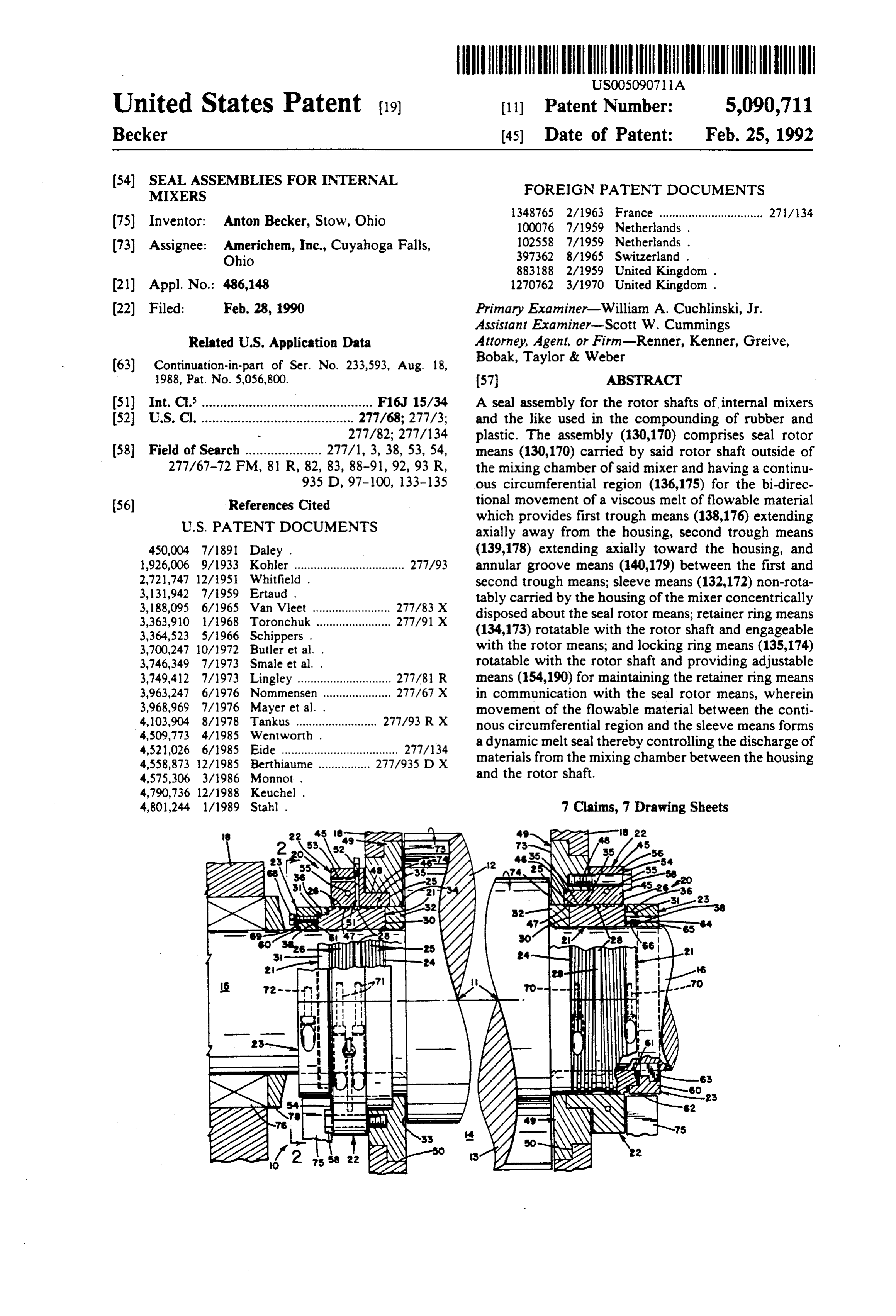
4,801,244 1/1989 Stahl. 7 Clains, 7 Drawing Sheets 22 Rapz 2 22
NSNEEZ
3 SVes N2x NN N&2%
NRS
III
Page 2
Drawing sheet — no readable text.
Page 3
Drawing sheet — no readable text.
Page 4
Drawing sheet — no readable text.
Page 5
Drawing sheet — no readable text.
Page 6
Drawing sheet — no readable text.
Page 7
Drawing sheet — no readable text.
Page 8
Drawing sheet — no readable text.
Page 9
causes softening of this seal type which results in defor
SEAL ASSEMBLIES FOR INTERNAL MIXERS mation under sealing pressure and accelerated wear. A third variation of the face type seals is the reverse
CROSS-REFERENCE TO RELATED action seal in which the sealing force is generated by the APPLICATIONS internal pressure of the mixer. The escaping material This application is a continuation-in-part of U.S. Ser. generates a pressure against a rotating sealing ring No. 233,593, filed Aug. 18, 1988, now U.S. Pat. No. which is allowed to float in the axial direction and gen 5,056,800. erate a sealing pressure on the opposing seal higher than the mixer pressure. This type of seal does not require
TECHNICAL FIELD O external adjustment or loading to function, but has the High intensity internal mixers, of which the Banbury same problem as the other face type seals. type is an example, are used in the rubber and plastic Another type of seal is the close clearance, tempera industry to soften, melt, mix and/or dispense compo ture controlled seal. This seal is not externally lubri nents and additives during the compounding of various cated and it is applicable to nonabrasive, self-lubricating formulations. Due to the action and design of the mixer 15 materials such as polyolefins and the like. The sealing is rotors and the application of pressure by the air loaded achieved by temperature control of the gland to solidify ram, the contents of the mixing chamber tend to leak the polymer which generates its own seal. The major between the rotor shafts and the mixer chamber. While problem with this type of seal is that only a limited this is a minor problem for the compounding of rubber, range of materials can be processed. Abrasive additives when plastics are compounded the materials are more 20 or corrosive materials wear the gland and shaft rapidly. costly and their loss is a significant problem. and the increased clearance causes the seal to leak. Numerous attempts have been made to design seals Another type is the pumping screw or forwarding that contain the material, provide a reasonable service screw seal. Seals of this design are utilized in various life, have a low manufacturing cost and are preferably applications and employ on the rotor shaft spiral quickly and easily changed. The present invention pro 25 grooves which generate a forwarding force and pump vides an apparatus and method to create a dynamic melt the polymer toward the inside of the mixer. The prob seal, or viscous O-ring for use with rotors of internal lem associated with this design is that when internal mixers.
pressure of the mixer decreases below the pumping
BACKGROUND OF THE INVENTION 30 pressure of the seal spiral, dislodged material is pumped back into the main melt.
As noted above, a variety of seals have been designed Finally, the labyrinth type seal employs an array of for internal mixers. The packing type of seal is one concentric grooves in the rotor or in the stationary part example and it employs an adjustable packing gland and a shaft seal comprising a wear ring of glass filled Teflon. with close clearance to provide the sealing function. A shortcoming of this design is the necessity of constant 35 The principle of this seal arrangement is that leaking material must flow across a closed clearance dam into adjustment of the packing gland in order to make up for the adjacent groove. If sufficient stages of labyrinth wear. The gland pressure causes increased friction on grooves are provided, material leak could be eliminated the rotor shaft which requires higher driving torque and or a controlled leak could result. Problems are also causes shaft wear.
Another design comprises the face type seals. One associated with this type of seal. First, due to deflection version is spring loaded in which the application of the of the rotor shafts, clearances must be relatively large spring load generates pressure on the sealing face which resulting in considerable leak flow which, in turn, ne contacts the shaft. As the internal pressure increases, cessitates long labyrinth seal. Second, grooves may more spring force is required which generates higher become filled with solid or degraded material rendering friction and heat. This heat, in turn, causes faster seal 45 the seals ineffective.
face deterioration, specifically if polymer seal materials Thus, despite the widespread existence of Banbury are used. As the seal face wears, the spring force on the and other types of high intensity internal mixers for seal surface diminishes which allows more compound to more than 50 years and the many and varied designs for leak. When processed compounds are very abrasive, as seals, a structure has not been provided heretofore that is true for halogenated thermoplastics and abrasive is effective in sealing the rotors, particularly in environ additives, accelerated wear and seal failures result. ments that are abrasive or corrosive or both such as the As a variation, some face type seals are loaded with compounding of certain thermoplastic formulations. hydraulic or pneumatic cylinders to compensate for SUMMARY OF THE INVENTON wear of the sealing surface. The pressure or load re mains constant, it does not decrease with wear as spring 55 It is therefore an object of the present invention to loaded seals. In some seal designs, external lubrication is provide a seal assembly that is useful for providing a incorporated to reduce friction and wear between the seal for the rotors of high intensity internal mixers. rotating and stationary seal faces. It is another object of the present invention to pro Several problems that limit the use of this type of seal vide a seal assembly that creates a dynamic, viscous include lubricant flow into the mixer cavity and leaks O-ring from the material within the mixer. from the seal area which contaminate the surrounding It is another object of the present invention to pro area necessitating frequent clean-up. Also, the seal lu vide a seal assembly that can accommodate rotor shaft bricant selected must be compatible with the material deflections, has a long service life, a reasonable manu being processed. In some instances, operating tempera facturing cost and is relatively easy to install and main tures may cause degradation of the lubricant. Lastly, 65 tal.
some polymeric seal faces contain molybdenum disul It is yet another object of the present invention to fate, graphite or other lubricants and operate without provide a seal assembly that permits changes of material external lubrication. Friction generated temperature and/or the color of the material to be made without the
Page 10
necessity of cleaning the seal as is required in existing PREFERRED EMBODIMENT FOR CARRYING apparatus.
OUT THE INVENTION
It is another object of the present invention to pro vide a method for creating a dynamic, viscous O-ring The present invention provides a seal assembly for seal for rotors that is effective with the compounding of 5 the rotors of high intensity internal mixers which are thermoplastic polymers. particularly useful in instances where plastic formula It is another object of the present invention to pro tions are being compounded. Such mixers are well vide a method for creating a dynamic, viscous O-ring known and include a mixing chamber and one or more seal that minimizes the loss of compounds, including rotors which are provided with blades that operate to powdered materials, and which does not permit escap 10 work the mixture of rubber or plastic against the surface ing material to flow back into the mixing chamber. of a surrounding mixing chamber as well as between These and other objects, together with the advan blades in multiple rotor apparatus. The action of the tages thereof over known seal designs and related meth blades performs a kneading action on rubbery and plas ods, which shall become apparent from the specification tic materials and works into the material the various which follows, are accomplished by the invention as S other components that are desired in the mixture. hereinafter described and claimed. Typically, during the mixing operation, a small por In general, a seal assembly for the rotor shafts of tion of the material is driven between the rotors and internal mixers and the like comprises seal rotor means housing that forms the internal chamber and out of the carried by the rotor shaft outside of the mixing chamber apparatus. In order to minimize this action, seals are of the mixer and having a continuous circumferential employed to control movement between the housing region for the bi-directional movement of a viscous melt and the rotors. These are customarily lubricated to of flowable material which provides first trough means decrease friction and wear and occasionally the lubri extending axially away from the housing, second trough cant works its way into the mixing chamber. When means extending axially toward the housing, and annu rubber is being compounded, the loss of material is not lar groove means between the first and second trough 25 a serious problem, nor is the entry of seal lubricant into means; sleeve means non-rotatably carried by the hous the mixing chamber a problem, particularly where the ing of the mixer concentrically disposed about the seal rubber formulation contains oil.
rotor means; retainer ring means rotatable with the For the compounding of plastics, most lubricants rotor shaft and engageable with the rotor means; and 30 would contaminate the mixture and, therefore, it is locking ring means rotatable with the rotor shaft and customary to select a compatible material such as dioc providing adjustable means for maintaining the retainer tyl phthalate, which is a plasticizer for many formula ring means in communication with the seal rotor means, tions, but not an inexpensive remedy. Another problem wherein movement of the flowable material between is the loss of components from the mixer. Such losses the continuous circumferential region and the sleeve 35 are not readily quantifiable which gives rise to varia means forms a dynamic melt seal thereby controlling tions in the formulation and, many of the ingredients the discharge of materials from the mixing chamber lost are rather expensive which, in turn, increases the between the housing and the rotor shaft. cost of the plastic resin being compounded.
BRIEF DESCRIPTION OF THE DRAWINGS
Still another difficulty unique to plastic compounding is that some formulations, particularly those containing
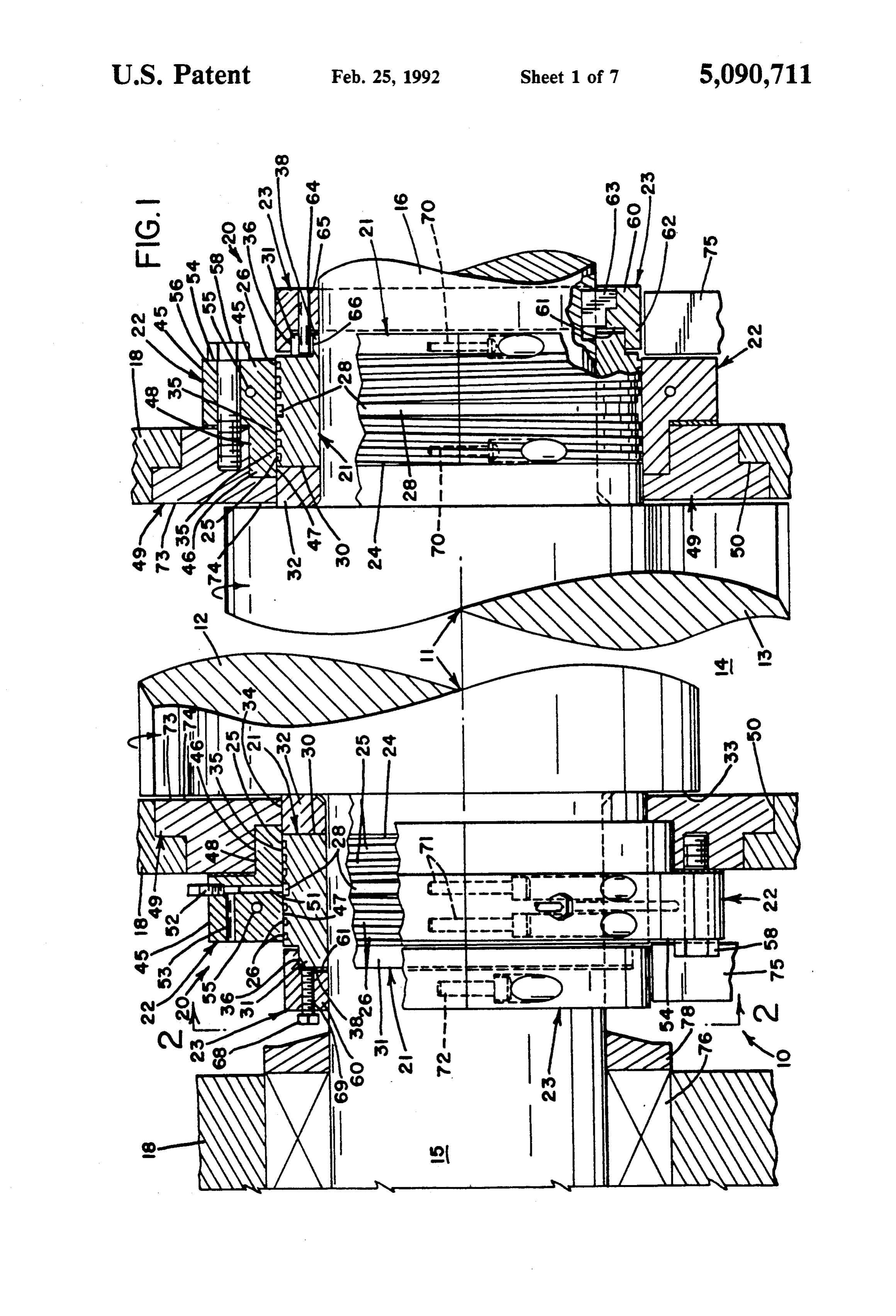
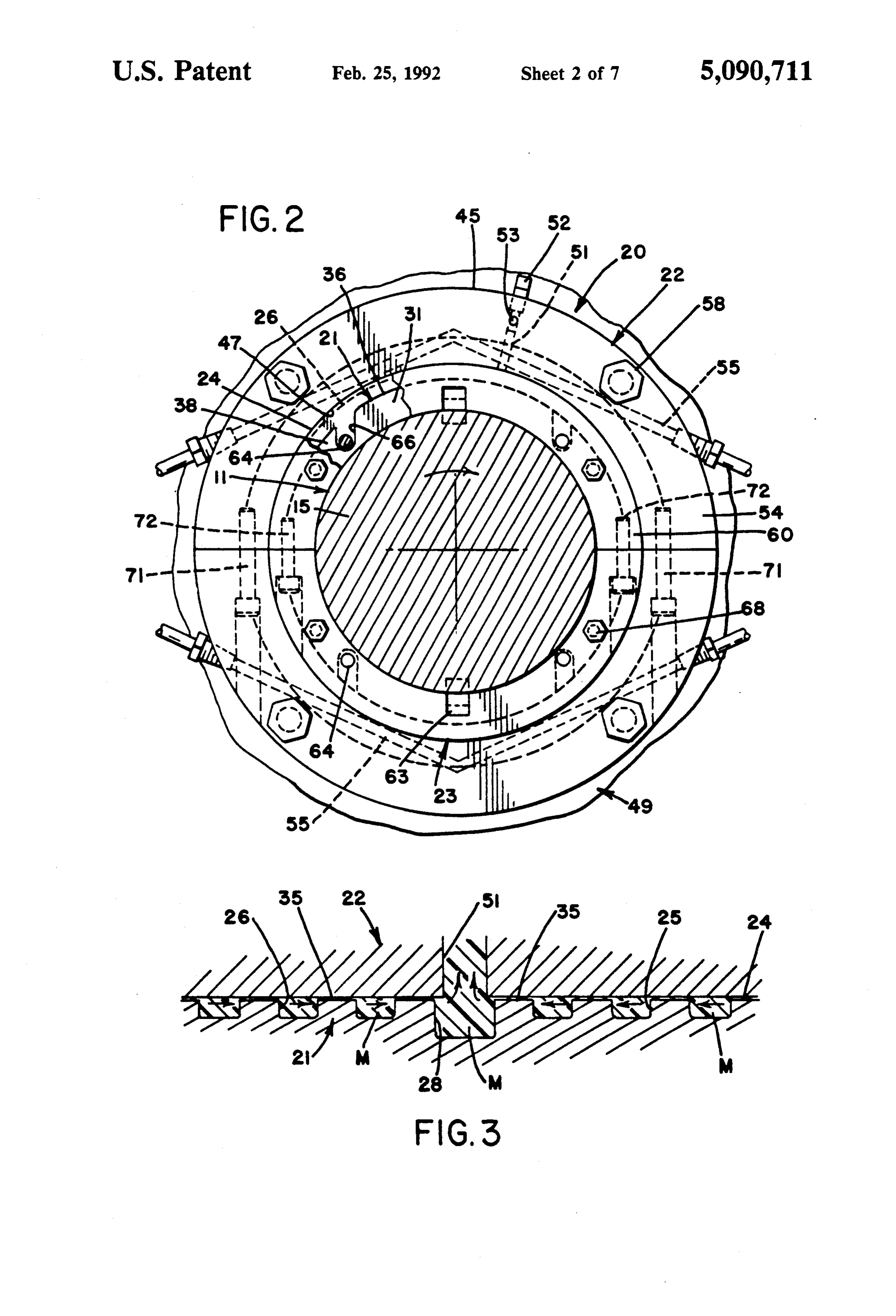
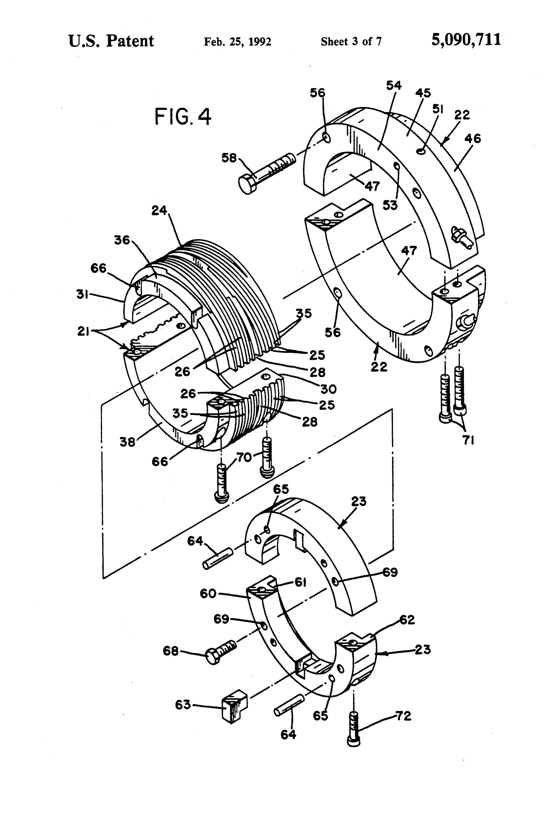
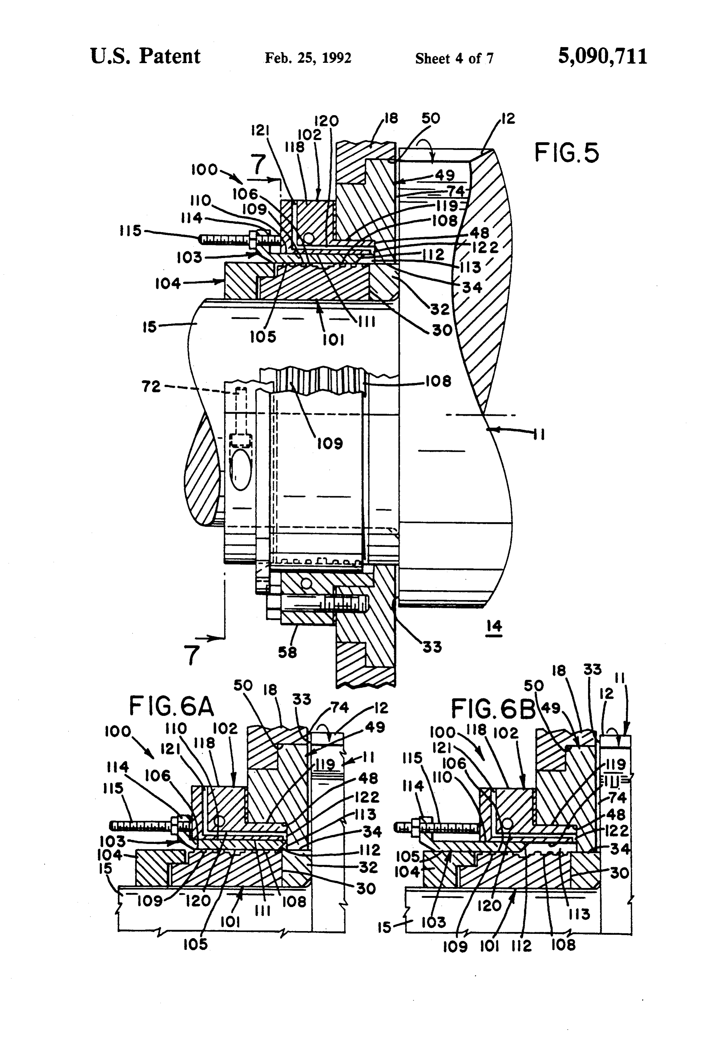
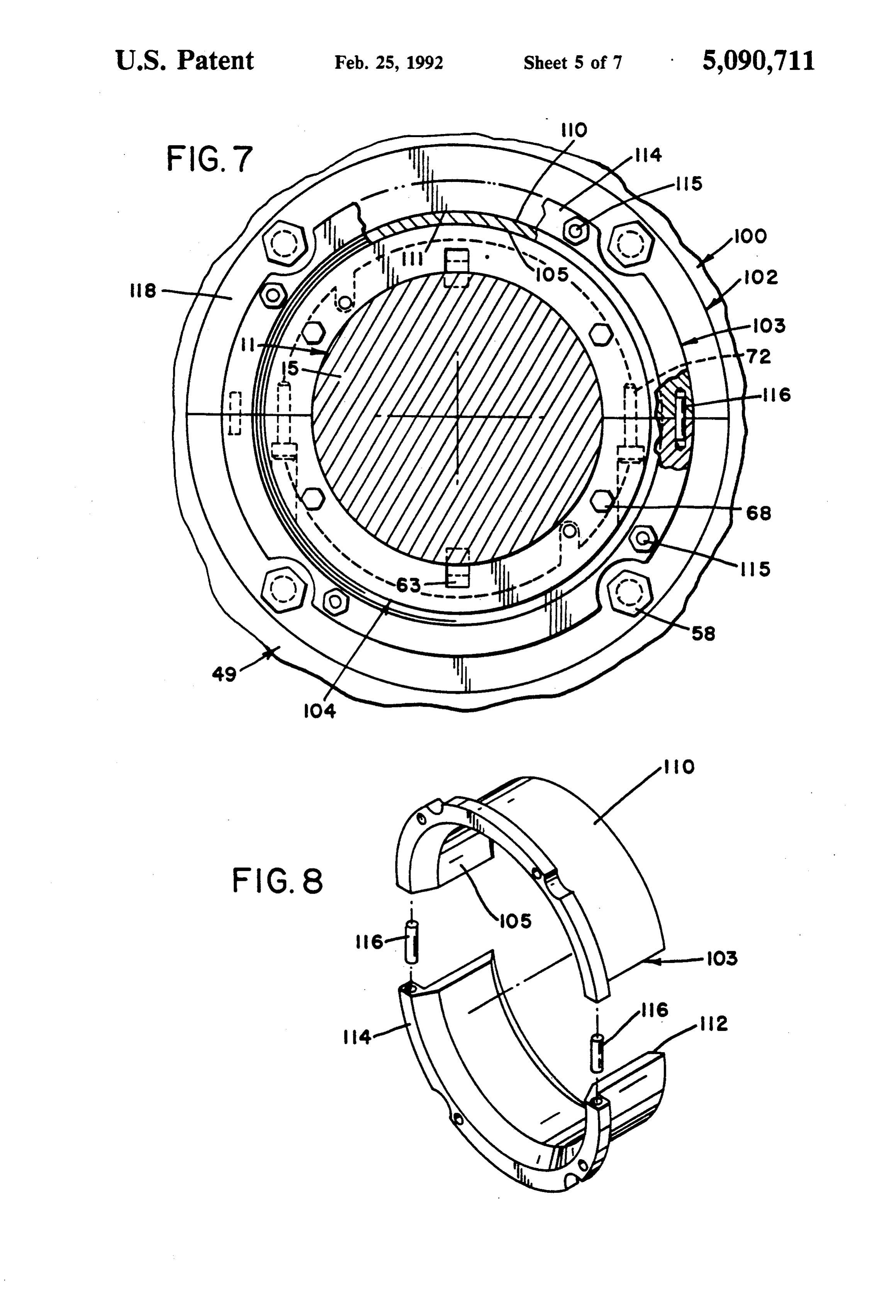
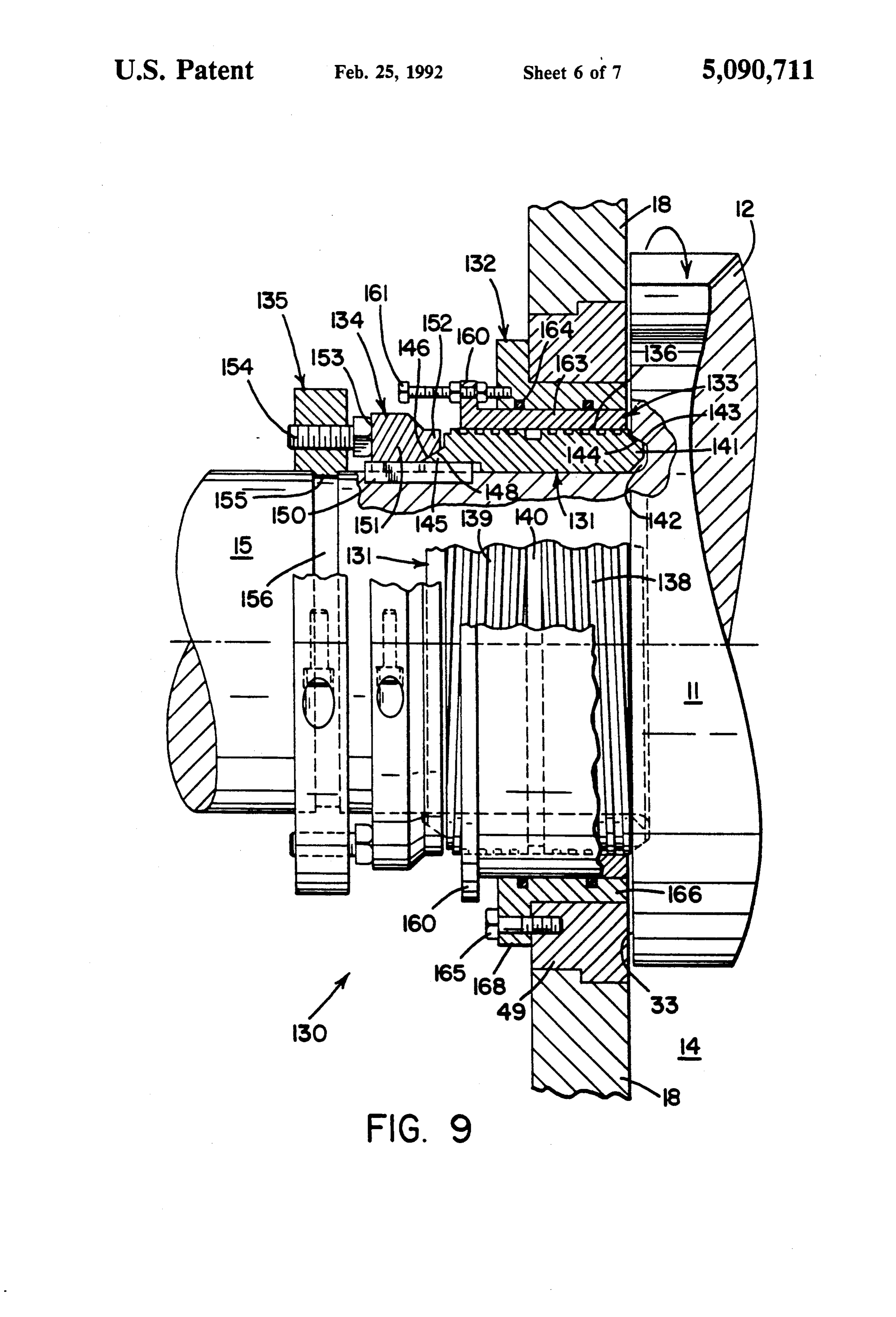
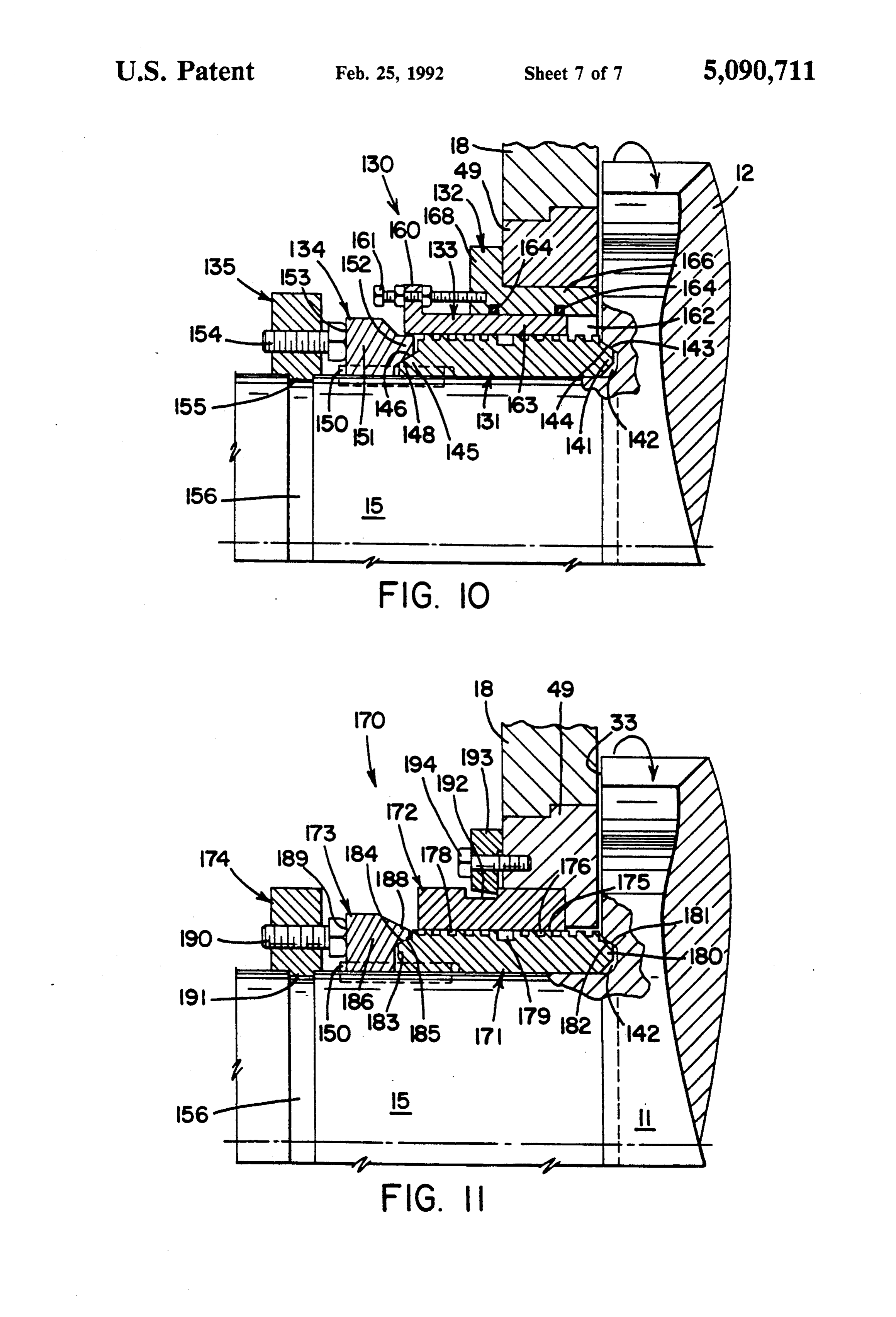
FIG. 1 is a side elevation, partially in section, depict halogenated polymers, are corrosive to the seals. Most ing the seal assembly of the present invention in con plastic formulations are also sensitive to heat and if junction with one rotor of an internal mixer; allowed to become entrapped in the seal areas they FIG. 2 is a cross-section taken substantially along the scorch and form hard particles. These particles are not line 2-2 of FIG. i; 45 only abrasive to the seal and surrounding components, FIG. 3 is an enlarged cross-sectional view depicting but if they are worked back into the mixing chamber, the adjacent surfaces between the seal rotor and sleeve they will eventually form an imperfection in the plastic means of the seal assembly; article manufactured from the resin. FIG. 4 is an exploded perspective depicting the seal Because these problems exist with all known internal rotor, seal means and retainer means of the present mixers, the seal assembly and related method of the invention; present invention can be employed in substantially any FIG. 5 is a partial side elevation, partially in section, design of apparatus and thus, practice of the present depicting an alternate embodiment of the present inven invention is not to be limited to any specific type of tion; mixer, such as a Banbury, or size of mixer. Similarly, FIGS. 6A and 6B depict sequentially stages of opera 55 while the problems attendant the compounding and tion of the balancing element of FIG. 5; mixing of plastics are particularly hard on seals, practice FIG. 7 is a cross-section taken substantially along line of the present invention is not limited to embodiments 7-7 of FIG. 5; where plastics are compounded, but also includes rub FIG. 8 is an exploded perspective depicting the bal ber compounding as well as other materials. ancing element of FIG. 5; With respect now to the drawings, the internal por FIG. 9 is a side elevation, partially in section, depict tion of a typical mixer 10 is depicted in FIG. 1. The ing an alternate embodiment of the present invention; mixer 10 is shown with a single rotor 11, having blades FIG. 10 is a side elevation, partially in section, depict 12 and 13 which are contained within a mixing chamber ing the seal assembly of FIG. 9, showing movement of 14. The rotor 11 and chamber 14 have been partially the balancing element; and 65 broken away and, therefore, the interrelation of the FIG. 11 is a partial side elevation, partially in section, blades with the natingly configured troughs of the depicting an alternate embodiment of the present inven chamber 14 has not been depicted. The rotor 11 pro O. vides left and right axial shafts, 15 and 16 respectively,
Page 11
S 6 which pass through the housing walls of the mixer 10, A radial port 51 is provided through the body portion indicated by the numeral 18. 45 in alignment with the annular groove 28 of seal rotor The seal assembly of the present invention is indi 21. It can be capped with a valve 52 or similar device cated generally by the numeral 20. It is to be appreci and an axial port 53 may be optionally channeled ated that one seal assembly 20 is provided in conjunc through the rear wall 54 of body 45 into radial port 51. tion with the shafts 15 and 16 at each side of the mixer The purpose and use of ports 51 and 53 shall be ex 10 and that the description of one is applicable to both. plained hereinbelow. A plurality of chord segment The seal assembly includes three elements: seal rotor channels 55 are also provided in sleeve means 22 for the means 21; sleeve means 22 and retainer ring means 23. circulation of cooling medium or heating medium, as In greater detail, the seal rotor 21 fits concentrically 10 necessary, to control movement of viscous melt mate about the shaft 15 and carries a continuous circumferen rial passing between seal rotor 21 and sleeve means 22 as tial portion, indicated generally by the numeral 24. will also be described hereinbelow. Finally, a plurality Moving outwardly from the chamber 14, circumferen of axial bores 56 are provided through the body 45 for tial region 24 provides an inner or first set of spiral 5 the receipt of bolts 58 which affix sleeve means 22 to troughs 25, which extend axially away from the housing wear plate 49 so that sleeve means 22 is non-rotatably in the manner of a right hand thread. An outer or sec held by the housing 18.
Retainer ring means 23 comprises a cylindrical flange ond set of spiral troughs 26 from the circumferential which also fits upon the shafts 15 and 16. Retainer ring portion 24 extend axially toward the chamber in the 23 provides a body portion 60, the inner wall of which manner of a left hand thread. Where first and second 20 61 is adjacent end wall 38 of outer flange 31, and an troughs 25 and 26 meet, an annular groove 28 may be axially extending leg 62 which overlaps and matingly provided which is deeper and wider than the troughs 25 engages the outer cylindrical wall 36 of outer flange 31. and 26 provided by the circumferential region 24. Retainer ring 23 is affixed to the shaft 15 with key 63 The seal rotor 21 terminates at its forward end with a and is rotatable therewith.
face 30 and at the trailing end with an outer flange 31.
A wear ring 32 is interposed between rotor face 30 and 25 andA 66 plurality of shear pins 64 are driven into bores 65 in retainer ring 23 and seal rotor means 22, re the shoulder 33 formed by the rotor blades 12 and 13 and provides an outer, cylindrical wall 34 of the same spectively so that the latter is rotatable with the former diameter as the lands 35 of troughs 25. The wall 34 is ably engaged 15.
and the shaft One or more jack screws 68 are thread contiguous with the leading edge of troughs 25 and 26. 30 of retainer ring 23.axial in an bore 69 provided in the body 60
Outer flange 31, at the other end of seal rotor 21, is the face 38 of outer flangeendThe of jack screw 68 engages 31 and maintain the wear ring likewise contiguous with the trailing edge of troughs 26. 32 firmly against the shoulder 33 of the rotor 11. It has an outer cylindrical wall 36 of a lesser diameter In order to install the seal assembly, the seal rotor 21, than the wall 34 of ring 32 and terminates with an exte sleeve means 22 and retainer ring 23 are each manufac rior face 38. 35 tured in halves, as depicted in FIG. 4. The halves of seal While wear ring 32 is depicted in the drawings, it is rotor 21 are positioned around a shaft 15 and then fas not a necessary element of the seal assembly 20 but is tened together with bolts 70. In similar fashion, the instead an element often present in mixing apparatus. halves of retainer ring 23 are also positioned around Where the ring 32 is not employed, it is within the scope shaft 15 behind seal rotor 21 and fastened together with of the present invention to abut seal rotor face 30 bolts 71. Finally, the halves of sleeve means 22 are posi against the shoulder 33 in which instance the spiral tioned within the housing 18 and fastened together with troughs 25 may begin adjacent face 30 or a short axial bolts 72. Shear pins 64 are positioned and jack screw 68 distance therefrom. adjusted, as described above, and the assembly is ready The seal rotor 21 carried by shaft 16 is the mirror for operation.
image of the seal rotor carried by shaft 15 and thus 45 Having thus described the basic component elements provides a circumferential portion with continuous of seal assembly 20, the operation thereof to form a inner or first spiral troughs 25 of left hand orientation dynamic melt seal, and practice of the method of the and outer or spiral troughs 26 of right hand orientation present invention shall be next provided. with an annular groove 28 therebetween. The purpose During mixing of the materials within the internal for the opposite hand of the troughs will be explained chamber 14, small quantities will eventually be worked herebelow. The remaining elements of the seal rotor out between the shoulders 33 of rotor blades 12 and 13 carried by shaft 16 are identical to those carried by shaft and the leading edge 73 of wear plates 49. From the 15 and shall therefore not be repeated. space 74 therebetween, the material passes along the The sleeve means 22, comprises an L-shaped cylindri inner spiral troughs 25 until each is filled and continues cal member having a central body portion 45 and an 55 to move away from the housing until it collects in the inwardly extending leg 46. Both body portion 45 and annular groove 28. Continued drive or movement of leg 46 form a continuous cylindrical inner wall or sleeve material from the chamber 14 will eventually exceed 47 which is contiguous with the lands 35 of inner and the capacity of annular groove 28 in which instance the outer troughs 25 and 26, respectively. Sleeve 47 is co material enters the outer spiral troughs 26. Because the axial with the inner troughs 25 and the outer troughs 26. orientation of these troughs is opposite that of the The leg 46 fits within a notch 48 provided in wear plate troughs 25, the material is moved axially back toward 49 which is provided in a suitable recess 50 in housing the housing and is thereby simultaneously returned to member 18. Wear plate 49, or the equivalent structure, the annular groove 28. The troughs 25 and 26, in effect, is customarily provided by the manufacturer of the provide an opposed pumping action, as depicted in mixer 10 and as such, does not constitute an element of 65 FIG. 3, which pressurizes the material M within the the seal assembly 20. Nevertheless, in order to obtain annular groove to form a fluid, dynamic O-ring and stop contact between the sleeve 47 and circumferential por further material leakage. It is to be appreciated that the tion 24, the notch 48 must be provided. orientation of the inner and outer spiral troughs must be
Page 12
opposite each other and that the directions are depen sleeve means 102. The axial end 112 of element 103 dent upon the direction of rotation of the rotor 11. In terminates a short distance from the notch 48 of wear this manner, the desired pumping action toward the plate 49 to define a small cylindrical space 113. At the annular groove 28 is achieved. opposite end of element 103 a radial flange 114 is pro It should be appreciated that whether the material 5 vided which articulates with suitable means 115 for being compounded is rubber or plastic, it will behave as movement of the balancing element 103 toward and a putty-like or dough-like semi-solid. Also, as the tem away from the wear plate 49, as depicted in FIGS. 6A perature of the mixture rises during mixing, the material and 6B. Means 115 can include a manually operated or becomes more flowable, generating a viscous melt. power operated mechanism, an example of the former While this has a tendency to increase the likelihood the O being the threaded shaft depicted in the drawings. Bal material will be driven out of the chamber, it also in ancing element 103 is also preferably manufactured in sures that a continuous supply of material is driven to halves, as depicted in FIG. 8, which can be suitably the groove 28 thereby providing a dynamic O-ring joined together via pins 116 or other means. which is very effective in the sealing the chamber As should be apparent, movement of the balancing against further discharge of material. 15 element 103 away from the notch 49 will uncover more Should any material pass totally beyond the second, of the inner troughs 108 while increasing the volume in outer spiral troughs 26, scraper blades 75 can be posi the space 113. This, in turn, allows more of the material tioned behind sleeve means 22 to effect removal by a driven from the cavity 14 to enter the space 113. scraping movement before the material can reach the The sleeve 102, it will be noted, is similar to sleeve 22, thrust bearing 76 (depicted schematically) convention 20 comprising a body portion 118 and a leg 119 extending ally carried on the shafts 15 and 16 beyond the seal therefrom. The thickness of leg 119 is decreased ap assemblies 20. Also, a dust deflector 78 can be provided proximately to accommodate the presence of balancing before the bearings, as is known. element 103. An axial bore 120 extends through the leg With respect again to FIG. 1, the radial port 51 pro 119 and a portion of the body 118 and communicates vided in sleeve means 22 can be employed as a drain 25 with a radial port 121 which passes outside of the body. channel which is utilized for controlled bleeding of the A small bore 122 is provided at the opposite end of axial annular ring 28 when materials are compounded that bore 120 and opens into the space 113. rapidly degrade. Operation of the valve 52 will vary the In operation, axial positioning of the balancing ele volume of material that is bled. Another useful feature ment 103 causes more pumping troughs on one side to of the radial port 51 is that by maintaining a controlled 30 be engaged and less on the opposing side. Provision of bleed of material through the annular groove 28, there this element facilitates the control of the pumping direc is no chance for any residue to build up, scorch and then tion and amount of leak flow, and it also may be used to return back into the chamber 14. compensate for variations in polymers, bulk density and In the event a build-up of stagnant material does operating conditions.
occur, particularly during periods of nonoperation, the 35 Regarding the port 121, it is useful for the processing axial port 53 can be utilized for the injection of molten of difficult to melt materials, materials having a high or liquid purge material to solubilize any solid residue content of inorganic fillers, highly degradable com remaining in the port 51, groove 28 or even the troughs. pounds and extremely abrasive additives. These may Port 53 can also be utilized as an injection port for not readily allow for the formation of a dynamic melt cleaning operation, thereby obviating disassembly of 40 O-ring seal during operation of the mixer and, therefore, the seal assembly 20. Despite the presence of these fea a low melt polymer can be injected via port 121 to form tures, there remains the possibility that an appreciable the dynamic seal. A similar result could be obtained by quantity of material may cool down and solidify in the injecting a low melt polymer into one of the ports 52 or seal assembly between periods of nonoperation. In such 54 of the seal assembly 20. The port 121 could also be instances the functional engagement between the seal 45 utilized for cleaning operations involving the injection rotor 21 and sleeve means 22 is tremendous, such that of molten purge materials.
subsequent start-up of the rotors 11 can develop excess Two final embodiments are depicted in FIGS. 9-11, loads. For this reason, shear pins 64, discussed herein which shall be discussed next. With references first to above, are provided between the retainer ring 23 and FIGS. 9 and 10, another modified seal assembly, in seal rotor 21 allowing the rotor 11 and retainer 23 to dicted generally by the numeral 130, is presented. It is rotate without torquing the seal rotor 21 until it can be similar to the seal assembly 100 and includes seal rotor freed from the sleeve 22. means 131, sleeve means 132, pressure balancing ele With respect now to FIGS. 5-8, an alternate embodi ment 133, retainer ring means 134 and locking ring ment of the present invention shall be discussed. A means 135.
modified seal assembly, indicated generally by the nu 55 Seal rotor means 131 is functionally similar to seal meral 100, is provided and includes. Seal rotor means rotor means 21 and 101, but provides a modified struc 101, sleeve means 102, pressure balancing element 103 ture. While it carries a circumferential region 136 pro and retainer ring means 104. The design and operation viding first and second troughs 138, 139 which meet of seal rotor means 101 and retainer ring means 104 are centrally at an annular groove 140, it also carries a identical to the elements 21 and 23 of seal assembly 20 forward lip 141 which is received within an annular and, therefore, shall not be discussed here. recess 142 carried in the shoulder 33 of rotor blades. The additional element of seal assembly 100 is pres The recess 142 may be machined into shoulder 33 if it is sure balancing element 103 which is interposed between not already present. Lip 141 and recess 142 provide seal rotor 101 and sleeve means 102. It comprises a mating inclined surfaces 143, 144, respectively, which cylindrical sleeve having a radially inner surface 105, 65 assist with the alignment and placement of seal rotor contiguous with the lands 106 of inner and outer means 131 about shaft 15. At the opposite end, seal rotor troughs 108 and 109, and a radially outer surface 110, means 131 terminates in a tail flange 145 which provides contiguous with the inner radial wall or sleeve 111 of an inclined or ramped surface 146. Surface 146, in turn,
Page 13
is engageable with a nating inclined surface 148 from for receipt of a key 150 which secures both elements to retainer ring means 134. Retainer ring means 134 and the shaft 15 for rotating therewith.
seal rotor means are provided with aligned keyways for Retainer ring means 173 is a cylindrical flange having receipt of a key 150 which secures both elements to the a central body portion 186 and an axially extending shaft 15 for rotation therewith. flange 188 which carries inclined surface 185. The rear Retainer ring 134 is a cylindrical flange having a ward face 189 is engageable with the head of an adjust central body portion 151 (FIG. 10) and an axially ex able positioning bolt 190, threadably received within tending flange 152 which carries inclined surface 148. locking ring means 174. The locking ring means 174 is The rearward face 153 is engageable with the head of substantially identical to element 135 of seal assembly adjustable positioning bolts 154 which are threadably O 130 and carries an inwardly directed annular foot 191 received within locking ring means 135. The latter ele that is received within groove 156, in shaft 15. By ad ment is a two piece cylindrical flange which carries an justment of bolt 190, the retainer ring means 173 urges inwardly directed annular foot 155, received within a the seal rotor 171 into the proper position about shaft groove 156, machined into shaft 15. As should be appar 15 15, as described hereinabove with respect to seal assem ent, by adjustment of the bolts 154, the retainer ring 134 bly 130.
urges the seal rotor means 131 into the proper position The sleeve means 172 is generally cylindrical and about shaft 15, with any slack being taken up by the encompasses the majority of the circumferential region inclined surfaces presented by lip 14 and tail flange 175 of seal rotor 171, most notably the annular groove 45. 179. On its outer circumference, an annular recess 192 is Pressure balancing element 133 and sleeve means 132 20 provided. A plurality of clamps 193 are fastened via are similar to the components 103 and 102 of seal assem bolts 194 to wear plate 49 which fit within recess 192, bly 100. Balancing element 133 is interposed between thereby holding sleeve means 172 in a non-rotatable the seal rotor 131 and sleeve means 132 and carries a fashion about seal rotor 171. radial flange 160 which articulates with suitable means 25 As should be apparent from the foregoing descrip 161 for movement of the element 133 toward and away tion, the seal assemblies 130 and 170 provide a novel from (FIG. 10) rotor shoulder 33. Means 161 can in manner of location about the shaft 15, with proper posi clude a manually operated or power operated mecha tioning of the respective seal rotors being facilitated by nism for changing the volume of space 162 (FIG. 10). adjustment of bolts 154, 190 from elements 135 and 174, The cylindrical sleeve 163 of balancing element 133 30 respectively. It is also to be understood that a similar can be sealed within sleeve means 132 via O-rings 164, seal assembly 130 or 170 would be employed on the or the mating surfaces can be threaded, in which in other shaft 16 of the mixer 10. stance, the balancing element 133 can be "threaded' in Thus, it should be evident that the seal assemblies of and out of sleeve means 132, as desired. Sleeve means the present invention provide a highly effective means 132 is fastened to wear plate 49 via bolts 165 and is thus 35 for forming a seal between the rotor shaft and mixing stationary with respect to rotation of the shaft and seal chamber of internal mixers. Wear on the seal is of little rotor 131. While sleeve means 132 does not contain axial consequence because the seal can be formed by a small and radial passageways communicating between the portion of the mixture that would otherwise be lost space 162 and the outside environment, it is within the from existing mixing apparatus. Moreover, the con skill of the art to substitute the sleeve means 102 for trolled loss of material, also possible by practice of the sleeve means 132 and vice versa, depending upon the present invention, is a sure means of eliminating type of seal assembly desired. scorched residues from forming or re-entering the mix Sleeve means 132 comprises a cylindrical body por ing chamber. Finally, the assemblies allow for the injec tion 166 and a leg 168, extending radially outwardly tion of separate purge materials as well as low melt therefrom. The body portion 166 provides a cylindrical 45 materials that can form a seal more readily than the sleeve contiguous with the outer wall of the pressure material within the chamber.
balancing means 133. As depicted in the drawings, Based upon the foregoing disclosure, it should now where means 161 comprises a bolt, it can threadably be apparent that the use of the assemblies described engage leg 168. herein will carry out the objects set forth hereinabove. In FIG. 11, another variation of seal assembly is It should also be apparent to those skilled in the art that shown, referred to generally by the numeral 170. As the seal assemblies of the subject invention can readily sembly 170 is similar to the assembly 130 and includes be utilized in conjunction with various types of mixing seal rotor means 171, sleeve means 172, retainer ring apparatus and that the method of the present invention means 173 and locking ring means 174, but does not can be practiced to form a dynamic viscous seal from provide a balancing element. 55 the material being compounded within the mixer or Seal rotor means 171 is similar to seal rotor 131 of from a low melt polymer injected separately into the assembly 130 and provides a circumferential region 175, seal assembly.
providing first and second troughs 176, 178 which meet It is, therefore, to be understood that any variations centrally at an annular groove 179. It also carries a evident fall within the scope of the claimed invention forward lip 180 received within a recess 142 carried in and thus, the selection of specific component elements the shoulder 33 of the blades. Lip 180 and recess 142 can be determined without departing from the spirit of provide mating inclined surfaces 181, 182, respectively, the invention herein disclosed and described. More for alignment and placement of the seal rotor about over, the scope of the invention shall include all modifi shaft 15. At the opposite end a tail flange 183 is pro cations and variations that may fall within the scope of vided which provides an inclined surface 184 that is 65 the attached claims.
engageable with a mating inclined surface 185 from I claim:
retainer ring means 173. Retainer ring means 173 and 1. A seal assembly for the rotor shafts of internal seal rotor means 171 are provided with aligned keyways mixers comprising:
Page 14
seal rotor means carried by said rotor shaft outside of adjustable means engageable with said rearward the mixing chamber of said mixer and having a face for maintaining said retainer ring means in continuous circumferential region for the bi-direc communication with said seal rotor means; tional movement of a viscous melt of flowable wherein movement of said flowable material between material, said continuous circumferential region 5 said continuous circumferential region and said sleeve providing: means forms a dynamic melt seal thereby controlling first trough means extending axially away from the discharge of materials from said mixing chamber said housing: between the housing and said rotor shaft. second trough means extending axially toward said 2. A seal assembly, as set forth in claim 1, further housing; and O comprising:
annular groove means between said first and sec clamp means affixable to the housing and engageable ond trough means; with said annular recess for mounting said sleeve said seal rotor means providing means about said seal rotor means. a forward lip engageable with said rotor shaft; and 3. A seal assembly as set forth in claim 1, further a tail flange contiguous with said second trough 15 comprising means; pressure balancing means interposed between said said rotor shaft carrying blades providing a shoulder seal rotor means and said sleeve means. adjacent said housing and carrying a recess for 4. A seal assembly, as set forth in claim 3, wherein receipt of said lip; said pressure balancing means comprises: sleeve means non-rotatably carried by the housing of 20 a cylindrical sleeve movable, axially, between said said mixer concentrically disposed about said seal seal rotor means and said sleeve means; and rotor means, said sleeve means providing a cylin radial flange means at one end of said sleeve. drical element contiguous with said continuous 5. A seal assembly, as set forth in claim 4, wherein circumferential region of said seal rotor means and said sleeve means provides a body portion and leg ex having an annular recess about the outer periphery; 25 tending radially therefrom, said body forming said cy retainer ring means rotatable with said rotor shaft and lindrical element contiguous with the outer wall of said engageable with said rotor means while providing; pressure balance means.
a body portion; 6. A seal assembly, as set forth in claim 5, wherein an axially extending flange carrying an inclined said pressure balancing means further includes surface engageable with said tail flange; and 30 means for moving said means axially between said a rearward face; and, seal rotor means and said sleeve means. locking ring means rotatable with said rotor shaft and 7. A seal assembly, as set forth in claim 6, wherein providing said means for moving articulates with said radial flange an inwardly directed annular foot received within a groove provided in said shaft and 35
Provenance
- Collection
- Cited prior art
- Original PDF
- patentimages.storage.googleapis.com →
- Filed
- 1990-02-28
- Pages
- 14
- Method
- pdftotext (the PDF's own text layer) + pdftoppm 300dpi page scans
- Source
- Google Patents bibliographic record
- Granted
- 1992-02-25
- Inventors
- Anton Becker; Americhem Inc
- Transcribed from
- patentimages.storage.googleapis.com →