patent · US3963247
Shaft seal
15 June 1976
Page 1 — bibliographic record
United States Patent (19) 11 3,963,247 Nommensen (45) June 15, 1976 54) SHAFT SEAL 3,076,656 2/1963 Hofmann.............................. 277/6 3,558,238 1/1971 Van Herpt...................... 277/134 X (75) Inventor: Johan P. Nommensen, Stein, 3,622,164. 1 1/1971 Herbert............................... 277/134 Netherlands 3,746,350 7/1973 Mayer................................... 277/67 (73) Assignee: Stamicarbon B.V., Geleen,
Netherlands Primary Examiner-Samuel B. Rothberg
Attorney, Agent, or Firm-Cushman, Darby & 22 Filed: Feb. 19, 1975 Cushman
Related U.S. Application Data (57) ABSTRACT 63 Continuation-in-part of Ser. No. 203,689, Dec. 1 A visco-type seal S disclosed wherein a sealing pres 1971, abandoned. sure is built up in a fluid by means of one or more he lical windings, the fluid being enclosed in a narrow (30) Foreign Application Priority Data clearance between a stator and a rotor. The alignment Dec. 1, 1970 Netherlands 70 7502 of the rotor within the stator is insured by providing a
Netherlands.
701 7503 thin layer of material at the outer ends of at least one of the helical windings so that the clearance in a radial 52 U.S. Cl 277/16; 277/59; direction between the stator and the rotor at this loca 4 Aalb a . . . . . . . . . . . . . . . . . . . . . 27,67. 277 17.277/13 4 tion is less than the clearance existing in a radial direc 51) Int. Cl. Fi6. 15/40 tion between the helical windings and the stator. In (58 Field of search a w w w e o 277716, 13 4, 67, 73 one embodiment, the stator is designed as a sleeve -- - - - - - - --- - 27,/13 5.2 59 which has a flexible connection in the radial direction a with respect to a wall. The stator or a sealing element 56) References Cited fastened thereto is movable in an axial direction by means of a resilient force to obtain a proper sealing
UNITED STATES PATENTS when the device is at rest.
1,770,496 7/1930 Lawaczeck ....................... 277/67 X s 3,051,497 8/1962 Wigg et al......................... 277/16 X 8 Claims, 6 Drawing Figures
ANs,
Sarava
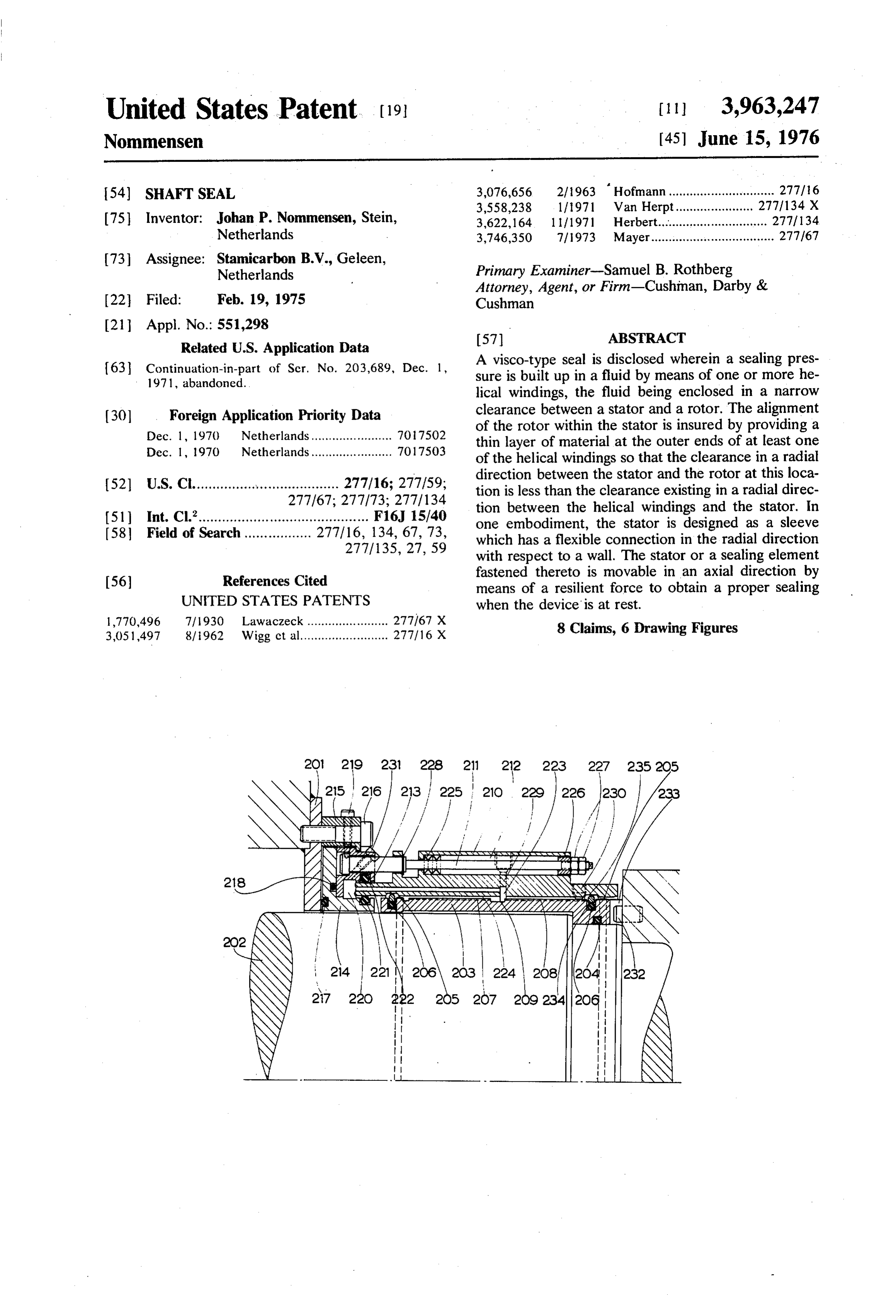
N 27 220 222 205 207 20g 2342O6 Q
NN | Š&
N --E. N
Page 2
Drawing sheet — no readable text.
Page 3
Drawing sheet — no readable text.
Page 4
Drawing sheet — no readable text.
Page 5
Drawing sheet — no readable text.
Page 6
Drawing sheet — no readable text.
Page 7
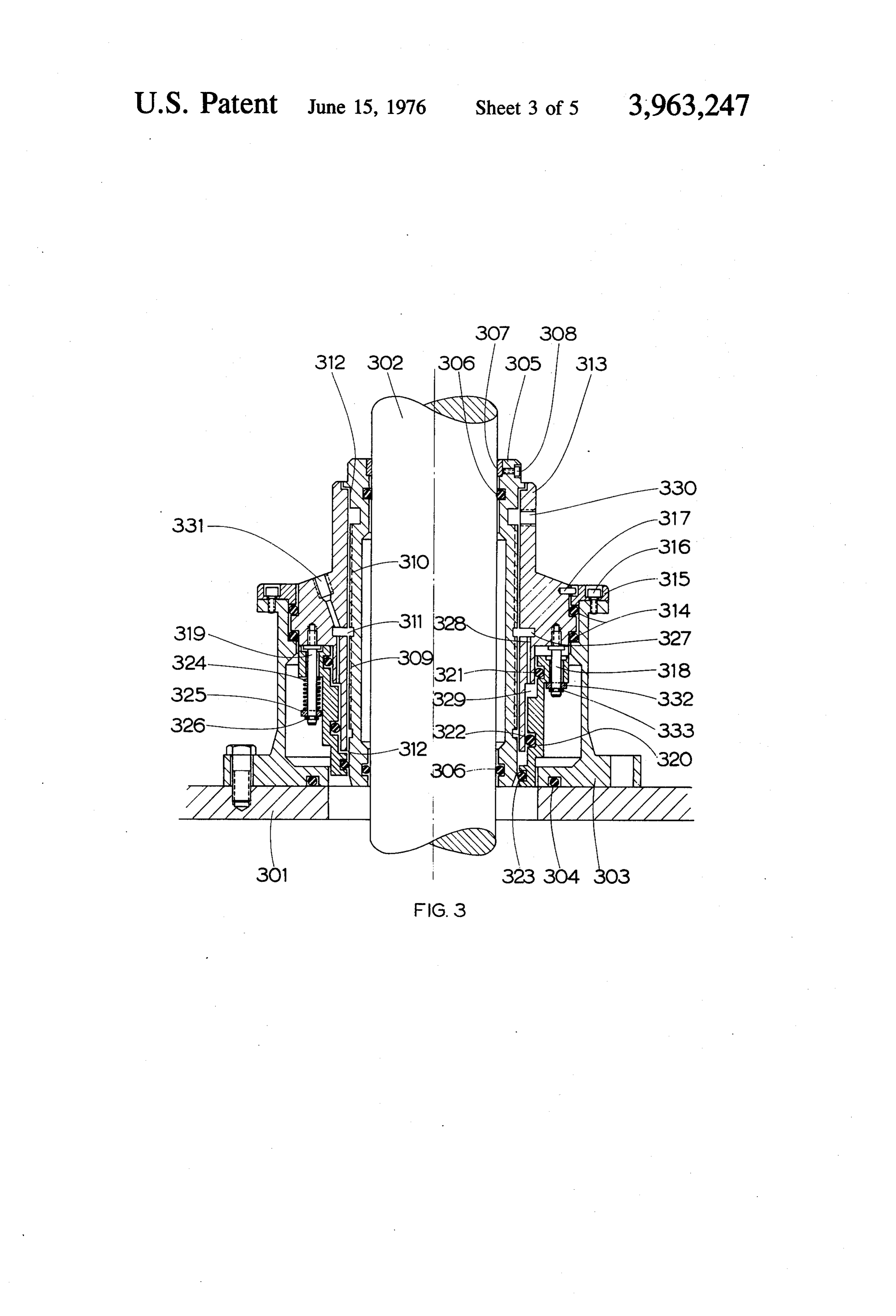
FIG. 3 illustrates a seal of an agitator shaft;
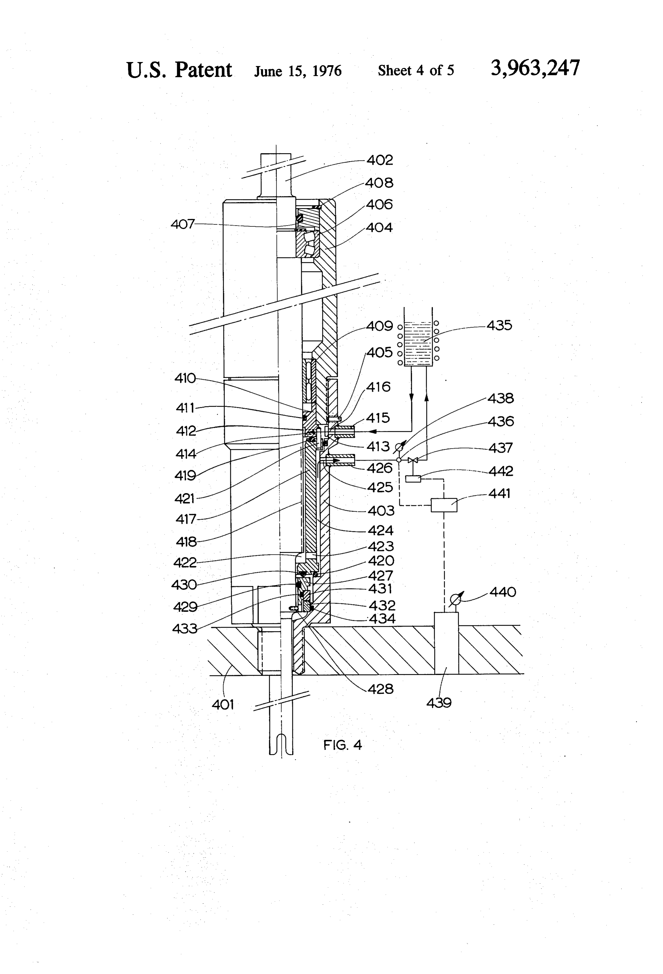
SHAFT SEAL FIG. 4 shows another embodiment of the seal of an BACKGROUND OF THE INVENTION agitator shaft, partially in elevation and partially in
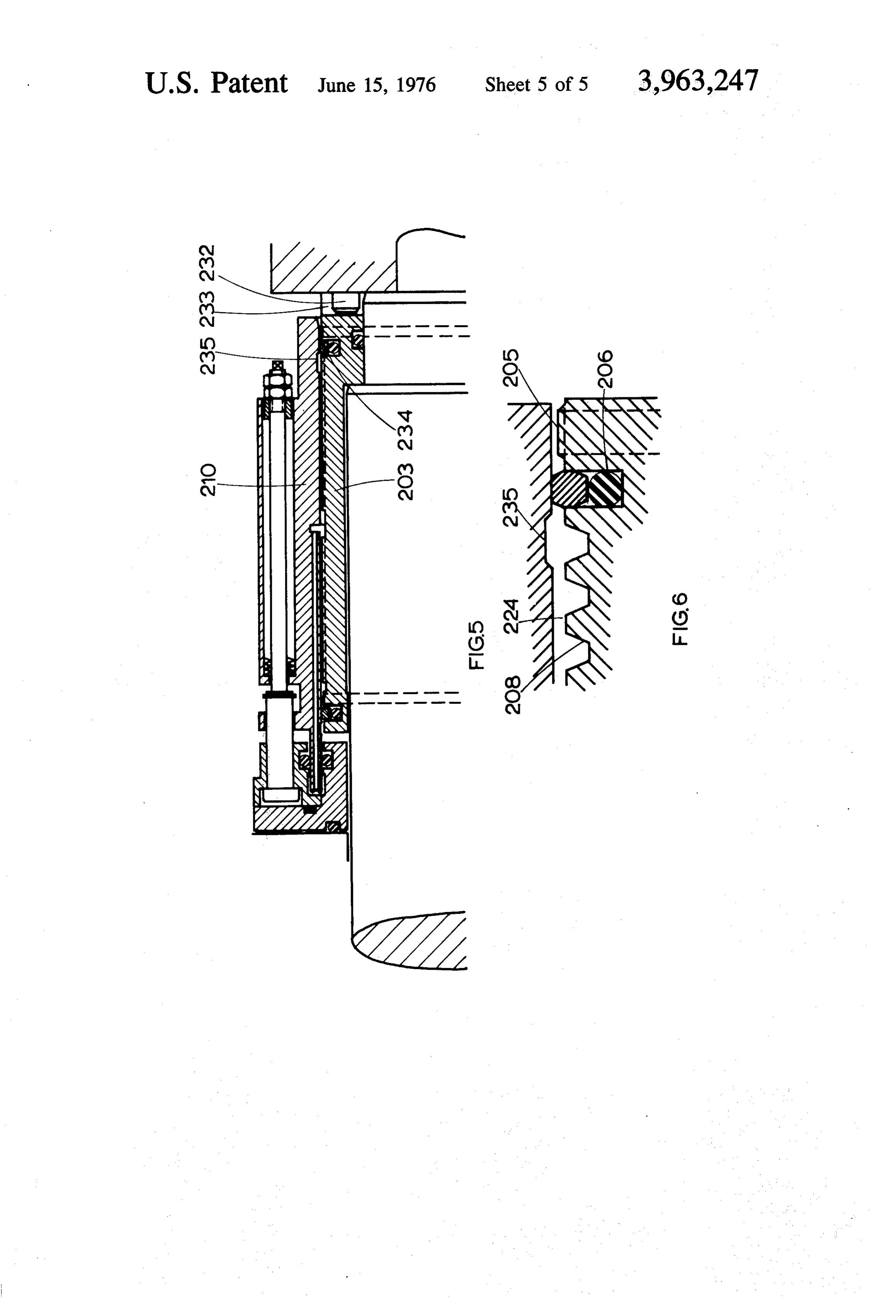
The present application is a continuation-in-part 5 FIG. 5 illustrates the embodiment of FIG. 2 when at application of Ser. No. 203,689 filed Dec. 1, 1971 now standstill; and abandoned. FIG. 6 is an enlargement of the encircled area shown The present invention relates to a sealing arrange in FIG.S.
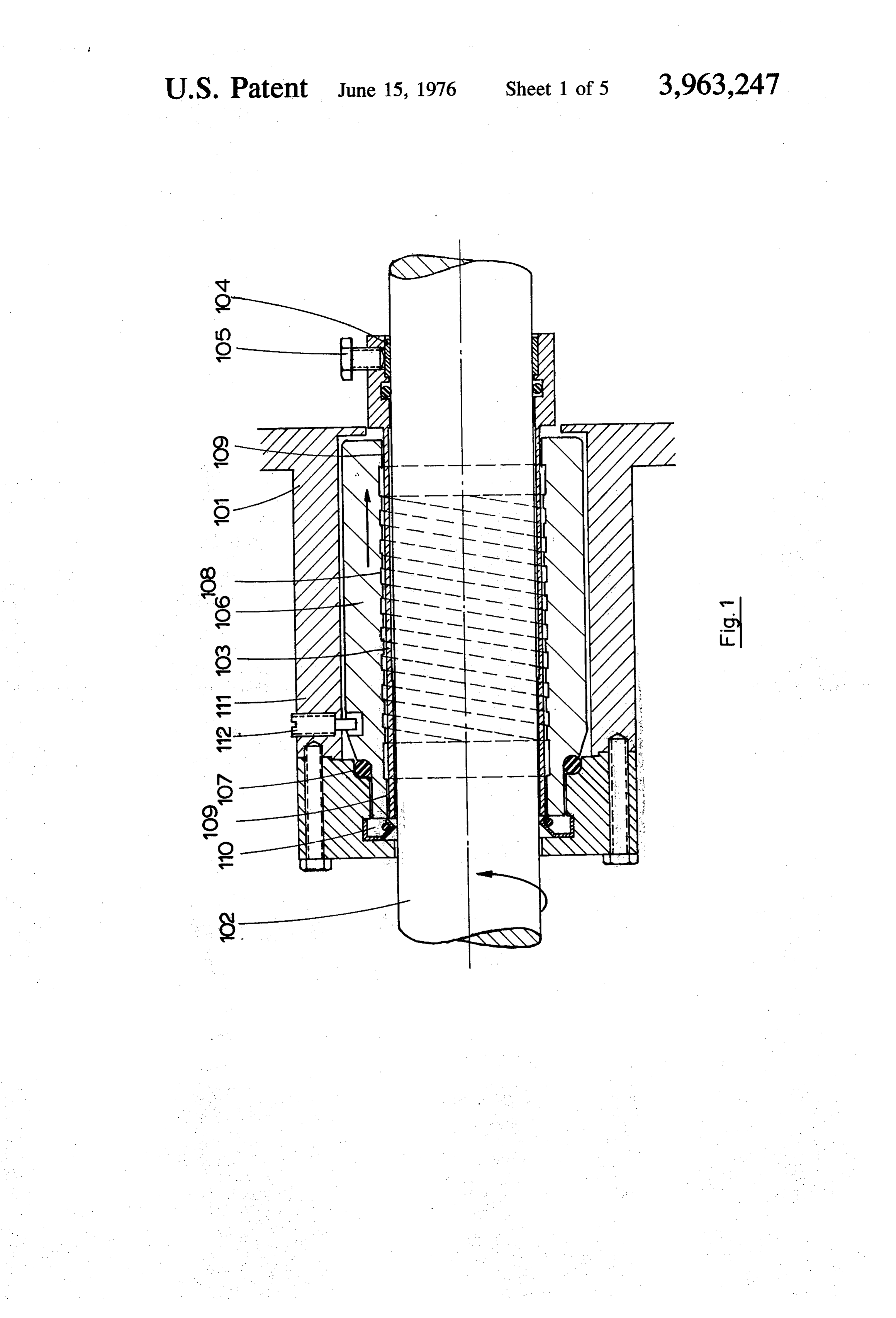
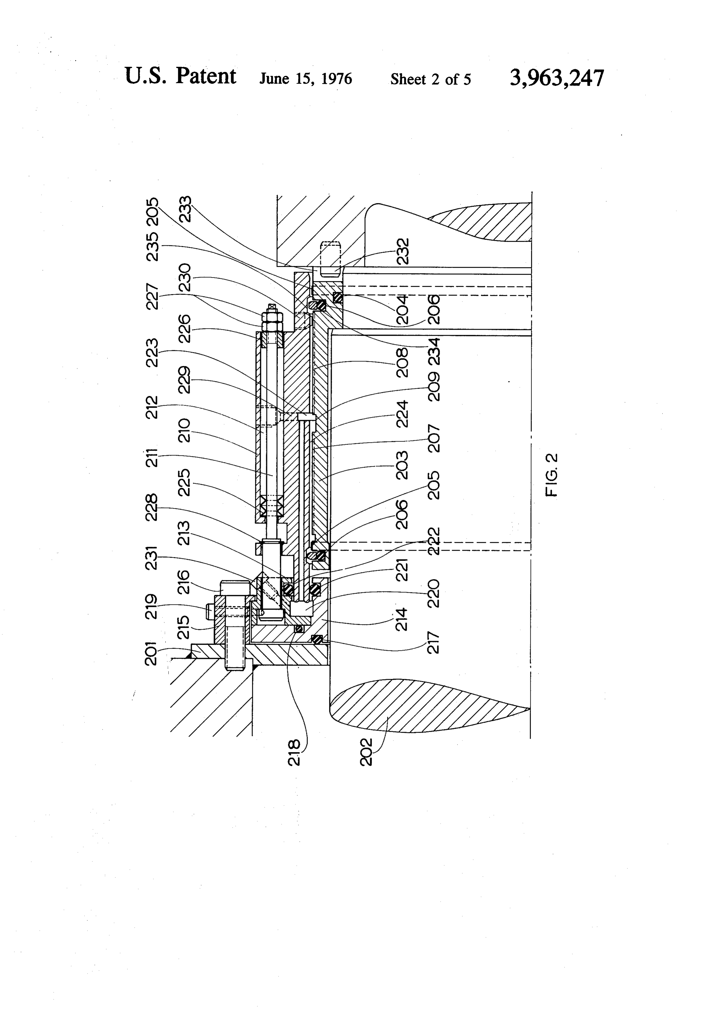
ment for a rotatable shaft which projects through a wall wherein during rotation of the shaft a sealing pressure 10 DETAILED DESCRIPTION OF THE INVENTION is built up in a fluid enclosed within a narrow annular Referring now to FIG. 1, there is shown a driving clearance between the shaft and a stator by means of shaft 102 carrying an impeller (not shown) projecting helical grooves rotating with the shaft whereby means through the wall 101 of a liquid ring compressor which are provided for maintaining a static seal when the is not shown in detail. A cylindrical rotor sleeve 103 is shaft is at standstill. 15 secured around shaft 102 and secured thereto by The present invention particularly relates to the pro means of a split ring 104 and a lock screw 105. vision of a "floating stator' whereby alignment of the Closely fitting around rotor 103 is a stator sleeve 106 shaft and the stator is improved at high speeds of rota which is sealed from the wall by means of a single 0 tion. It has been established that at high speeds of rota ring 107 and in this way can move relative thereto. tion (for instance, at a speed in excess of 1,400 rpm) 20 Stator 106 consists of suitable bearing material, such as the sealing pressure obtained is no longer directly pro bronze, white metal or carbon. In the surface of stator portional to the speed of rotation, possibly due to ec sleeve 106 which faces rotor 103, a single screw thread centricity of the shaft. 108 is provided having a clearance of, for instance, Accordingly, it is an object of the present invention 0.03 mm with sleeve 103. At the outer ends of screw to provide a sealing arrangementin which alignment of 25 threads 108 the stator sleeve is provided with a thin the shaft with respect to the stator is improved during layer of material 109 which has a smaller clearance, for rotation. instance 0.01 mm with the shaft. A locking pin 112 A further object of the present invention is to main projecting into a wide recess of the stator prevents the tain the required sealing pressure at high speeds of stator from rotating. The space between cover 111 and rotation. 30 shaft 102 contains a retaining ring 110 or a similar seal. Yet another object of the present invention is to The clearance between the stator and the rotor is filled substantially reduce the wear resulting on the helical with fluid. The grooves of screw thread 108 are so grooves during rotation and thus to extend the opera placed that this fluid is pumped to the housing of the tional life of the sealing arrangement. compressor (see arrow) when shaft 102 rotates. The present invention further contemplates that the 35 In the FIG. 2 embodiment, there is shown a rotatable rotor be provided with two helical windings running in shaft 202 of an extruder which projects through a wall opposite directions wherein an annular, cental cham portion 201 of the extruder. On the shaft a sleeve 203 ber is arranged inbetween the windings. The stator is is arranged, which sleeve is provided at its outer cir provided with a bore ending in the central chamber, the cumference with two helical thread profiles 207 and bore being used to move the stator or an axially mov 40 208 of identical pitch, profile 207 being left-handed able sealing element fastened to the stator, against and profile 208 being right-handed. Between both resilient force, as a result of which proper sealing is also thread profiles there is an annular space 209. achieved when the device is at rest. A pin 232 protrudes into a slot 233 of the sleeve so In case there exists a fluctuating pressure in the space that the sleeve rotates when the shaft rotates. An 0 to be sealed, for instance a stirred reactor, the stator 45 sealing ring 204 is provided which forms a seal between may be provided with apertures to which a supply and shaft 202 and sleeve 203.
a discharge line to and from a reservoir for sealing fluid On the cylindrical outer surface of each end of th are connected. The discharge line may comprise a sleeve 203 there is provided a thin layer 205 of molyb control valve which is actuated depending on the pres denum formed by a spraying on and regrinding opera sure in the space to be sealed. The static sealing at 50 tion to provide a shoulder. Also provided at each end of standstill can then be taken care of by a set of axially shaft 202 is a groove 234 containing composite sealing slidable slip rings. ring 206 consisting of an outer ring of Teflon (a regis BRIEF DESCRIPTION OF THE DRAWINGS tered Trade Mark) and an inner rubber ring, which in the position shown in FIG. 2 cooperates with a recess in
Novel features of the improved sealing arrangement 55 sliding sleeve 210.
in accordance with the present invention will be more Closely fitting to provide a minimum clearance of readily understood from a consideration of the follow 0.06 mm round the threaded part of sleeve 203 is a ing description taken together with the accompanying stator member in the form of a sliding sleeve 210. Slid drawing, in which certain preferred adaptations are ing sleeve 210 is adapted to slide in an axial direction illustrated with the various parts thereof identified by 60 over a plurality of rods 211 which pass through drilled suitable reference characters in each of the views, and channels 212 spaced around the circumference of slid in which: ing sleeve 210. The rods 211 are each provided with a FIG. 1 illustrates a longitudinal section of a first em head at one outer end and are fastened to the extruder bodiment of a shaft seal for the sealing of a liquid ring wall 201 by means of a ring 213 which encloses the compressor for circulation of chlorene gas; 65 head and which rests on an L-shaped ring 214 and by FIG. 2 illustrates part of a longitudinal section of the means of a ring flange 215 which is fastened to wall 201 seal of the shaft of an extruder for a viscous product by a plurality of bolts 216 distributed around the cir such as polyethylene solution in hexane; cumference thereof. An 0-ring 217 is inserted between
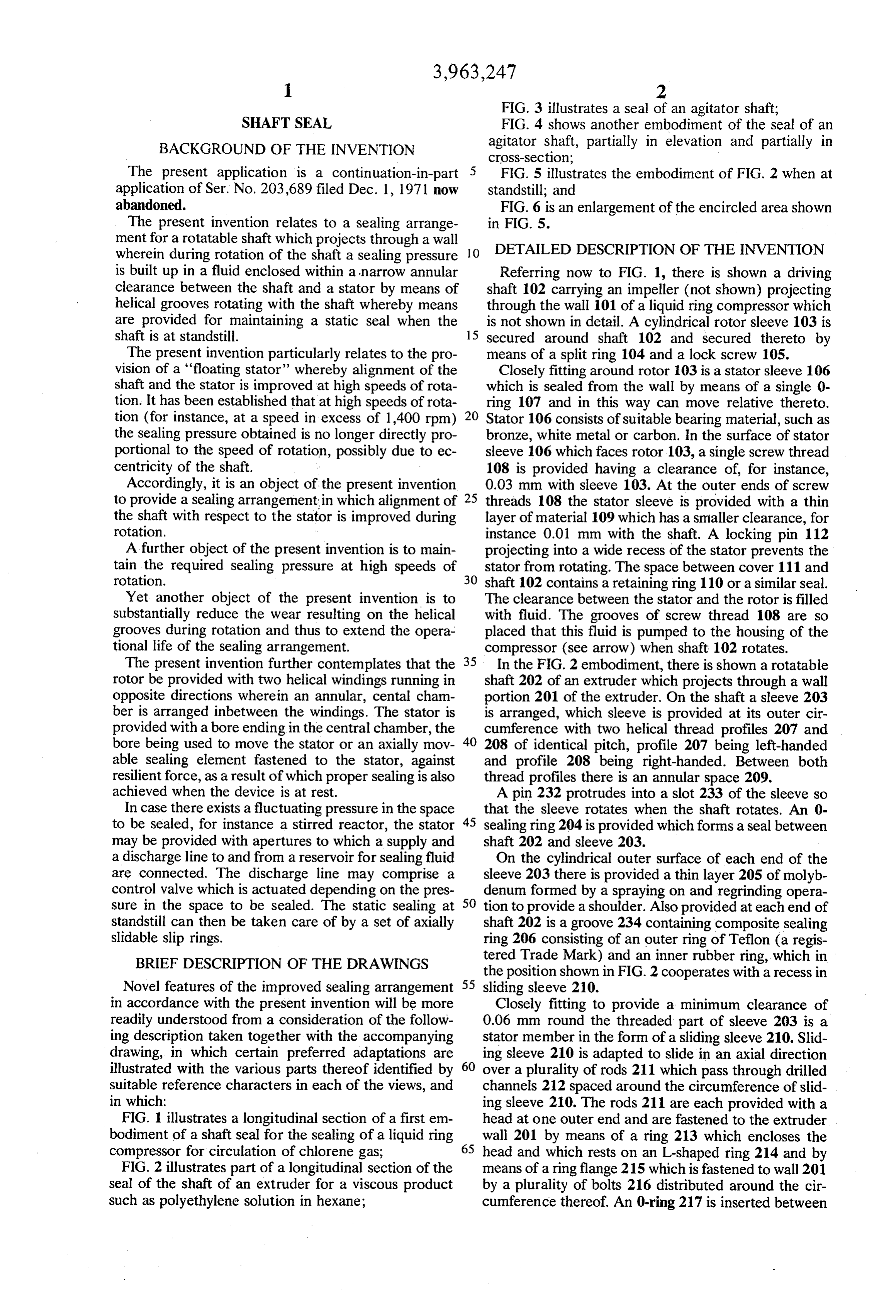
Page 8
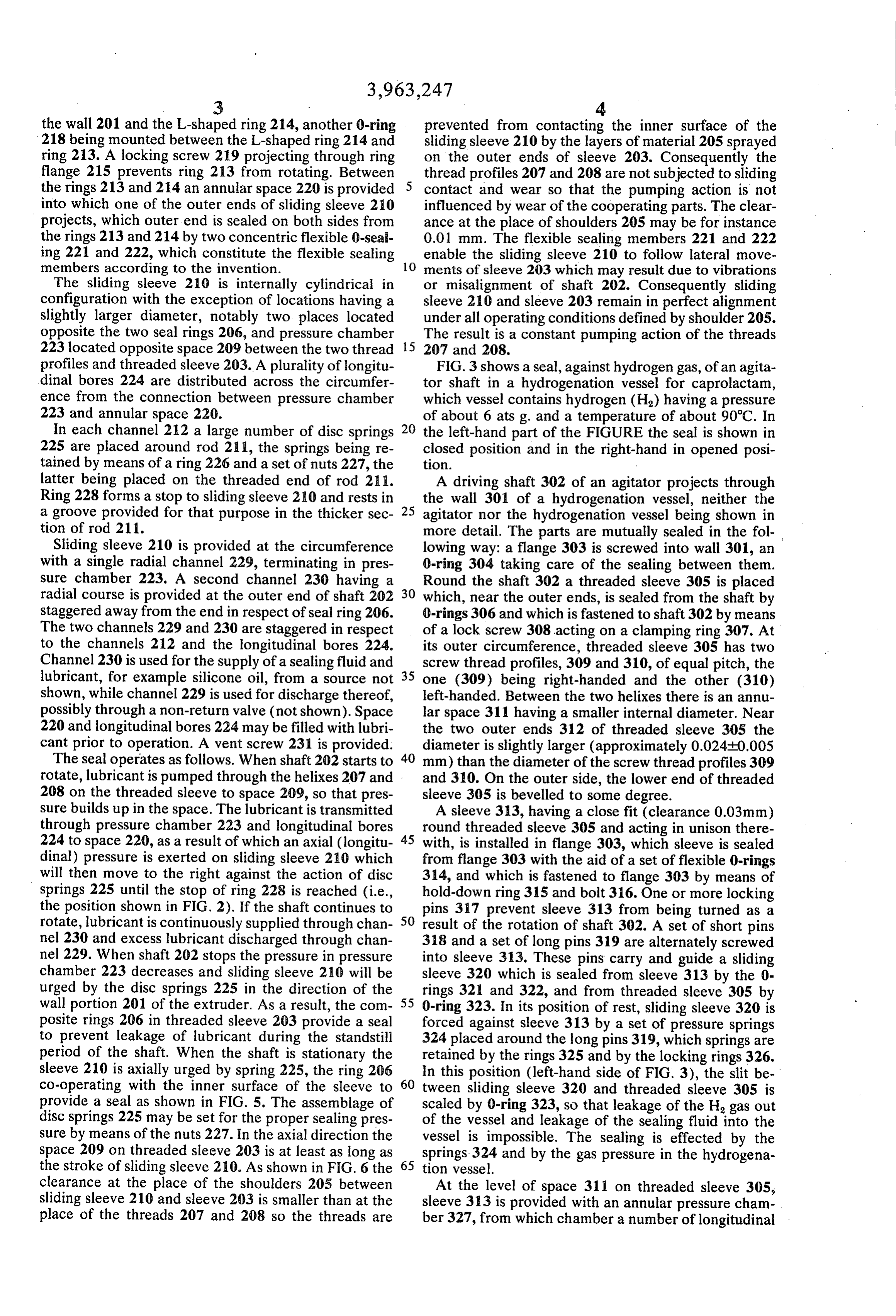
the wall 201 and the L-shaped ring 214, another 0-ring prevented from contacting the inner surface of the 218 being mounted between the L-shaped ring 214 and sliding sleeve 210 by the layers of material 205 sprayed ring 213. A locking screw 219 projecting through ring on the outer ends of sleeve 203. Consequently the flange 215 prevents ring 213 from rotating. Between thread profiles 207 and 208 are not subjected to sliding the rings 213 and 214 an annular space 220 is provided contact and wear so that the pumping action is not into which one of the outer ends of sliding sleeve 210 influenced by wear of the cooperating parts. The clear projects, which outer end is sealed on both sides from ance at the place of shoulders 205 may be for instance the rings 213 and 214 by two concentric flexible 0-seal 0.01 mm. The flexible sealing members 221 and 222 ing 221 and 222, which constitute the flexible sealing 10 enable the sliding sleeve 210 to follow lateral move members according to the invention. ments of sleeve 203 which may result due to vibrations The sliding sleeve 210 is internally cylindrical in or misalignment of shaft 202. Consequently sliding configuration with the exception of locations having a sleeve 210 and sleeve 203 remain in perfect alignment slightly larger diameter, notably two places located under all operating conditions defined by shoulder 205. opposite the two seal rings 206, and pressure chamber The result is a constant pumping action of the threads 223 located opposite space 209 between the two thread 5 207 and 208.
profiles and threaded sleeve 203. A plurality of longitu FIG. 3 shows a seal, against hydrogen gas, of an agita dinal bores 224 are distributed across the circumfer tor shaft in a hydrogenation vessel for caprolactam, ence from the connection between pressure chamber which vessel contains hydrogen (H2) having a pressure 223 and annular space 220. of about 6 ats g. and a temperature of about 90°C. In In each channel 212 a large number of disc springs 20 the left-hand part of the FIGURE the seal is shown in 225 are placed around rod 211, the springs being re closed position and in the right-hand in opened posi tained by means of a ring 226 and a set of nuts 227, the tion.
latter being placed on the threaded end of rod 2:1. A driving shaft 302 of an agitator projects through Ring 228 forms a stop to sliding sleeve 210 and rests in the wall 301 of a hydrogenation vessel, neither the a groove provided for that purpose in the thicker sec 25 agitator nor the hydrogenation vessel being shown in tion of rod 211. more detail. The parts are mutually sealed in the foll Sliding sleeve 210 is provided at the circumference lowing way: a flange 303 is screwed into wall 301, an with a single radial channel 229, terminating in pres 0-ring 304 taking care of the sealing between them. sure chamber 223. A second channel 230 having a Round the shaft 302 a threaded sleeve 305 is placed radial course is provided at the outer end of shaft 202 30 which, near the outer ends, is sealed from the shaft by staggered away from the end in respect of seal ring 206. 0-rings 306 and which is fastened to shaft 302 by means The two channels 229 and 230 are staggered in respect of a lock screw 308 acting on a clamping ring 307. At to the channels 212 and the longitudinal bores 224. its outer circumference, threaded sleeve 305 has two Channel 230 is used for the supply of a sealing fluid and screw thread profiles, 309 and 310, of equal pitch, the lubricant, for example silicone oil, from a source not 35 one (309) being right-handed and the other (310) shown, while channel 229 is used for discharge thereof, left-handed. Between the two helixes there is an annu possibly through a non-return valve (not shown). Space lar space 311 having a smaller internal diameter. Near 220 and longitudinal bores 224 may be filled with lubri the two outer ends 312 of threaded sleeve 305 the cant prior to operation. A vent screw 231 is provided. diameter is slightly larger (approximately 0.0240.005 The seal operates as follows. When shaft 202 starts to 40 mm) than the diameter of the screw thread profiles 309 rotate, lubricant is pumped through the helixes 207 and and 310. On the outer side, the lower end of threaded 208 on the threaded sleeve to space 209, so that pres sleeve 305 is bevelled to some degree. sure builds up in the space. The lubricant is transmitted A sleeve 313, having a close fit (clearance 0.03mm) through pressure chamber 223 and longitudinal bores round threaded sleeve 305 and acting in unison there 224 to space 220, as a result of which an axial (longitu 45 with, is installed in flange 303, which sleeve is sealed dinal) pressure is exerted on sliding sleeve 210 which from flange 303 with the aid of a set of flexible 0-rings will then move to the right against the action of disc 314, and which is fastened to flange 303 by means of springs 225 until the stop of ring 228 is reached (i.e., hold-down ring 315 and bolt 316. One or more locking the position shown in FIG. 2). If the shaft continues to pins 317 prevent sleeve 313 from being turned as a rotate, lubricant is continuously supplied through chan 50 result of the rotation of shaft 302. A set of short pins nel 230 and excess lubricant discharged through chan 318 and a set of long pins 319 are alternately screwed nel 229. When shaft 202 stops the pressure in pressure into sleeve 313. These pins carry and guide a sliding chamber 223 decreases and sliding sleeve 210 will be sleeve 320 which is sealed from sleeve 313 by the 0 urged by the disc springs 225 in the direction of the rings 321 and 322, and from threaded sleeve 305 by wall portion 201 of the extruder. As a result, the com 55 0-ring 323. In its position of rest, sliding sleeve 320 is posite rings 206 in threaded sleeve 203 provide a seal forced against sleeve 313 by a set of pressure springs to prevent leakage of lubricant during the standstill 324 placed around the long pins 319, which springs are period of the shaft. When the shaft is stationary the retained by the rings 325 and by the locking rings 326. sleeve 210 is axially urged by spring 225, the ring 206 In this position (left-hand side of FIG. 3), the slit be co-operating with the inner surface of the sleeve to 60 tween sliding sleeve 320 and threaded sleeve 305 is provide a seal as shown in FIG. 5. The assemblage of scaled by 0-ring 323, so that leakage of the H gas out disc springs 225 may be set for the proper sealing pres of the vessel and leakage of the sealing fluid into the sure by means of the nuts 227. In the axial direction the vessel is impossible. The sealing is effected by the space 209 on threaded sleeve 203 is at least as long as springs 324 and by the gas pressure in the hydrogena the stroke of sliding sleeve 210. As shown in FIG. 6 the 65 tion vessel.
clearance at the place of the shoulders 205 between At the level of space 311 on threaded sleeve 305, sliding sleeve 210 and sleeve 203 is smaller than at the sleeve 313 is provided with an annular pressure cham place of the threads 207 and 208 so the threads are ber 327, from which chamber a number of longitudinal
Page 9
bores 328 run to space 329 between-sleeve 313 and a bore 423 in sleeve 417, with space 424 between sliding sleeve 320 (and between the two 0-rings 321 sleeve 417 and housing 403. Near the upper end of and 322). Near the upper end, sleeve 313 is provided space 424, housing 403 is provided with a bore 425, to with a feed channel 330 that can be closed, as well as which a discharge-pipe 426 connects. with a feed channel 331 which can also be closed, the In the bottom part of housing 403 there is a sliding latter channel connecting with pressure chamber 327 ring holder 427 round shaft 402, which holder, by and being used for prior filling of the space between means of lock screw 428, is engaged when the shaft sleeve 313 and threaded sleeve 305 with a sealing fluid rotates, but which can move axially over the shaft. An which is at the same time a lubricant, such as silicone O-ring 429 seals the holder from shaft 402. In the lower oil MS 200. 10 face of sleeve 417, concentrically with O-ring 420, When shaft 302 starts to rotate (clockwise), sealing there is a second O-ring 430 to seal against sliding ring fluid is pumped through the two thread profiles 309 holder 427. Between sliding ring holder 427 and con and 310 to the spaces 311 and 327, causing a high necting piece 403 two hard metal sliding rings 431 and pressure to build up in these chambers (about 32 ats g. 432 are placed, one on top of the other. at 250 rp.m.). This pressure is hydraulically transmit 15 One O-ring 433 forms the seal between ring 431 and ted, via the longitudinal bores 328, to space 329 and holder 427, another O-ring, 434, forming the seal be exerts a downward force on sliding sleeve 320. As a tween ring 432 and housing 403.
result of this, sliding sleeve 320 moves downwards, A vessel 435 for the sealing fluid, for instance sili against the action of the springs 324, until it reaches the cone oil, which vessel can be heated if necessary, is stops, formed by the rings 332 and 333 on the short 20 connected to the feed, 415. The sealing fluid fills all pins 318. This situation is illustrated in the right-hand spaces between shaft 402 and housing 403. The dis part of the figure. - charge 426 in turn is connected to vessel 435 via a FIG. 4 shows the seal of a shaft for the agitator of a pressure gauge 436 and a control valve 437. If desired, pressurized reactor which is completely filled with liq the outlet pressure P of the visco seal 402, 417,418, uid and which is used for polymerization of ethylene in 25 can be read on meter 438.
solution. In reactor wall 401 a pressure gauge 439 is installed, The wall 401 of a reactor vessel not shown in more which is shown schematically, it being possible for the detail is passed through by a driving shaft 402 for an measured pressure P in the reactor to be read on a agitator (not shown in the drawing) located deeply in pressure meter 440. The pressures measured by the the reactor. Into wall 401 a sleeve-shaped connecting 30 gauges 436 and 439 are compared in control device piece or housing 403 is screwed which, at the level of 441. The output signal of control device 441 is set for wall 401, closely fits round shaft 402 without touching a constant pressure difference.
it and which, in upward direction, widens stepwise. Into The shaft seal operates as follows: Rotation of the the widest part of housing 403 a bearing bush 404 is 35 shaft 402 at a rate of, for instance,900 revolutions per screwed, and these parts are secured by means of a lock minute causes a sealing fluid pressure to be built up in screw 405. At the upper side, shaft 402 is supported in the visco seal 402,417,418, which, if control valve 407 a double-row barrel bearing 406, whose outer race is is in closed position, may increase to an excess pressure confined in bearing bush 404 with the aid of a locking of 120 atmospheres, and, if control valve 437 is fully piece 407 and a locking washer 408, the latter fitting a opened (so that the counter-pressure for the visco seal groove provided for this purpose in bush 404. Shaft 403 40 is practically zero), suffices to circulate about 4 liters is further supported in a double-row needle bearing per hour according to the arrows shown in the drawing. 409, the outer race of which is confined between a By setting the differential pressure between the visco shoulder of bearing bush 404 and a spacer 410 which is seal and the reactor to, for instance, 1 kg/cm on con clamped between a shoulder of housing 403 and the 45 trol device 441, the amount of sealing fluid to be circu lower end of bush 404. An O-ring 411 takes care of the lated by the visco seal is so regulated by the control seal between shaft 402 and spacer 410. device, using control valve 437, that the pressure of the At the level of the clamping, spacer 410 is provided visco seal is invariably 1 kg/cm higher than the reactor on both the inner- and outer-circumference with circu pressure.
lar recesses, 412 and 413, which are connected by The pressure difference over the slip ring seal formed means of one or more radial bores 414. A feed pipe 415 50 by the two sliding rings 431 and 432 amounts to 1 is installed on housing 403, which feed pipe communi kg/cm, as a result of which leakage of sealing fluid to cates with the outermost space 413 via a bore 416. the reactor is practically zero. At a reactor pressure of through the wall of housing 403. . 60 atmospheres and a visco seal pressure of 61 atmo In the space between shaft 402 and housing 403 there spheres 2 liters of sealing fluid per hour are circulated is a sleeve 417 round the shaft, the clearance with shaft 55 via storage vessel 435.
402 being substantially smaller than that with housing When pressure P in the reactor decreases, also the 403. At the level of the internally smooth sleeve 417, pressure in the visco seal decreases because control shaft 402 is provided with a continuous screw thread valve 437 is opened further by servo mechanism 442. 418 over part of its outer circumference. Alternatively, When the reactor pressure rises, also the pressure in . in case of a smooth shaft surface, the screw thread may 60 the visco seal rises because servo mechanism 442 re be provided on the inside of sleeve 417. Sleeve 417 is duces the passage of control valve 437. sealed from spacer 410 by an O-ring 419, and from When the shaft 402 is going to stop the pressure in housing 403 by O-ring 420, while being clamped be the visco seal falls off, while the reactor pressure forces tween these two parts 403 and 410. One or more lock the floating sliding-ring holder 427 and the sliding ring ing pins 421 prevent sleeve 417 from being rotated 65 432 upwards along shaft 402, sealing being then pro relative to spacer 410. vided by O-ring 430.
Between shaft 402 and the lower end of sleeve 417 The reactor liquid (polyethylene solution) does not there is an annular space 422 which communicates, via penetrate beyond the O-rings 420 and 430.
Page 10
When the agitator is started again, the visco seal rotation of the stator member and guided in said presses ring 427 down, so that the hard metal sliding housing member for limited axial movement rela rings 431 and 432 again turn on top of each other, with tive to said sleeve;
an extremely small leakage to the reactor. said stator member having helical windings on the For disassembly, after lock screw 405 has been un inner surface thereof in spaced relationship from done, bearing housing 404 can be unscrewed from the sleeve such that will produce a hydraulic pres housing 403, whereupon the entire visco seal can be sure between said sleeve and said stator member removed. Because of the high temperature (180°C) sufficient to produce axial movement of said stator allowance has been made for thermal expansion of the O member by action of said fluid on a surface of said materials, while sleeve 417, sealed by the O-rings 419, stator member presenting an area perpendicular to 420 and 430 is relatively free to move in radial direc said shaft, when said sleeve is rotated; tion and, hence, capable of optimum adjustment. a thin layer of material sprayed on said stator mem What is claimed is: ber at the ends of the windings so as to reduce the 1. A sealing arrangement for a rotatable shaft which 15 spaced relationship at said ends for aligning said projects through a wall comprising: sleeve within said stator member; and a sleeve mounted on said shaft for rotation therewith; static seal means interposed between said stator a stator member arranged concentrically about said member and said housing member for sealingly sleeve, fixed to prevent rotation thereof and guided engaging said stator member and said housing for limited axial movement relative to said sleeve; member when said sleeve is at rest; said sleeve having helical windings on the outer sur 20 spring means biasing said stator member in an axial face thereof in spaced relationship from the stator direction opposite from the direction of movement member such that will produce a hydraulic pres of said stator member in response to said hydraulic sure between said sleeve and said stator member pressure of said fluid, whereby said static seal sufficient to produce axial movement of said stator 25 means sealingly engages said stator member and member by action of said fluid on a surface of said said housing member when said sleeve is at rest. stator member presenting an area perpendicular to 6. A sealing arrangement as described in claim 5 said shaft, when said sleeve is rotated; wherein said thin layer of material comprises molybde a thin layer of material sprayed on said sleeve at the 1.
ends of the windings so as to reduce the spaced 7. A sealing arrangement for a rotatable shaft which relationship at said ends for aligning said sleeve projects through a wall comprising:
within said stator member; and a housing member;
static seal means interposed between said stator a shaft rotatably supported by said housing member; member and said sleeve for sealingly engaging said a stator member arranged concentrically about said stator member and said sleeve when said sleeve is 35 shaft, fixed to said housing member to prevent at rest; rotation of said stator member and guided in said spring means biasing said stator member in an axial housing member for limited axial movement rela direction opposite from the direction of movement tive to said shaft;
of said stator memmber in response to said hydrau said shaft having helical windings on the outer sur lic pressure of said fluid, whereby said static seal 40 face thereof in spaced relationship from the stator means sealingly engages said stator said sleeve when said sleeve is at rest.
member and member such that will produce a hydraulic pres sure between said shaft and said stator member 2. A sealing arrangement as described in claim 1 sufficient to produce axial movement of said stator wherein said thin layer of material comprises molybde member by action of said fluid on a surface of said
45 stator member presenting an area perpendicular to 3. A sealing arrangement as described in claim 1 said shaft, when said shaft is rotated; wherein said sleeve is provided with a pair of helical thin layer of material sprayed on said shaft at the windings each running in opposite directions, an annu ends of the windings so as to reduce the spaced lar central chamber being disposed between the pair of relationship at said ends for aligning said shaft windings, said stator being provided with a bore ending 50 within said stator member; and in said central chamber, the bore providing a passage static seal means interposed between said stator way for fluid pumped from said central chamber during member and said housing member for sealingly rotation of said shaft to an annular space at the end of engaging said stator member and said housing the bore, fluid pressure thereby being built up and used member when said shaft is at rest; to move the stator in an axial direction. 55 spring means biasing said stator member in an axial 4. A sealing arrangement as described in claim 3 direction opposite from the direction of movement wherein said thin layer of material comprises molybde of said stator member in response to said hydraulic
pressure of said fluid, whereby said static seal 5. A sealing arrangement for a rotatable shaft which means sealingly engages said stator member and . projects through a wall comprising: 60 said housing member when said shaft is at rest. a housing member; 8. A sealing arrangement as described in claim 7 a sleeve mounted on said shaft for rotation therewith;
a stator member arranged concentrically to said wherein U.
said thin layer of material comprises molybde sleeve, fixed to said housing member to prevent k is k is
Provenance
- Collection
- Cited prior art
- Original PDF
- patentimages.storage.googleapis.com →
- Filed
- 1975-02-19
- Pages
- 10
- Method
- pdftotext (the PDF's own text layer) + pdftoppm 300dpi page scans
- Source
- Google Patents bibliographic record
- Granted
- 1976-06-15
- Inventors
- Johan P. Nommensen; Stamicarbon BV
- Transcribed from
- patentimages.storage.googleapis.com →