patent · US6013968
Synchronous machine, in particular generator for motor vehicle
11 January 2000
Page 1 — bibliographic record
United States Patent (19) 11 Patent Number: 6,013,968 Lechner et al. (45) Date of Patent: Jan. 11, 2000 54 SYNCHRONOUS MACHINE, IN 5,539,265 7/1996 Harris et al. ............................ 310/263 PARTICULAR GENERATOR FOR MOTOR 5,543,676 8/1996 York et al. .............................. 310/263 VEHICLE 5,578,885 11/1996 Alford et al. ........................... 310/263 5,747,913 5/1998 Amlee et al. ........................... 310/263 75 Inventors: Juergen Lechner, 5,793,144 8/1998 Kusase et al. .......................... 310/263 Eberdingen-Nussdorf; Alexander 5,828,155 10/1998 Adachi .................................... 310/263 5,892,313 4/1999 Harris et al. ............................ 310/263
Shendi, Asperg, both of Germany;
Sylvan Briand, Magor, United FOREIGN PATENT DOCUMENTS
Kingdom
73 Assignee: Robert Bosch GmbH, Stuttgart, 2 281 665 3/1995 United Kingdom. Germany Primary Examiner Nestor Ramirez
ASSistant Examiner Thanh Lam 21 Appl. No.: 09/237,989 Attorney, Agent, or Firm Michael J. Striker 22 Filed: Jan. 26, 1999 57 ABSTRACT 30 Foreign Application Priority Data Asynchronous machine, in particular a generator for a motor Jan. 26, 1998 DE Germany ........................... 298 O1184 vehicle, has an excitation System with a plurality of electri cally excited individual poles in a rotor, preferably in form (51) Int. Cl. ................................................. HO2K 1/22 of claw poles which are excited by at least one common 52 U.S. Cl. .......................... 310/263; 310/268; 310/156; excitation coil, wherein for compensation of a magnetic 310/181; 310/261; 310/218; 310/45; 310/51; Stray flux, permanent magnets are inserted in free Spaces 310/264; 310/191 between the axially oriented claw poles on the pole plates 58 Field of Search ..................................... 310/263, 268, mounted on the axial ends of the rotors, and the permanent 310/156, 181, 261,218, 45, 51, 264, 191 magnets are Supported by a holder against centrifugal forces, So that the insertion of the permanent magnets is simplified 56) References Cited and facilitated by a simple and inexpensive holder which reduces parts and mounting expenses.
5,519,277 5/1996 York et al., 25 Claims, 3 Drawing Sheets
Page 2
Drawing sheet — no readable text.
Page 3
Drawing sheet — no readable text.
Page 4
Drawing sheet — no readable text.
Page 5
SYNCHRONOUS MACHINE, IN Alternatively, the holder is composed of two receiving PARTICULAR GENERATOR FOR MOTOR cages each having a ring disc, the ring discs are closed in the VEHICLE axial center of the rotor of the excitation System and abut against one another, edged Strip Sections are formed on the
BACKGROUND OF THE INVENTION ring discS which per each free Space form a receiving The present invention relates to a Synchronous machine, chamber for a permanent magnet which is closed at least and in particular to a generator for motor vehicles. toward the axial center of the rotor, toward centrifugally Synchronous machines of this type are known in the art. loaded side of the free Space and at least partially toward the One of Such machines is disclosed for example in the excitation call, and the receiving chambers are fixed on the German patent document DE 89 05353 U1. In this machine claw poles and/or the pole plates.
the permanent magnets located in the free Spaces between The both receiving cages of the holder are produced the oppositely located claw poles are oriented by holding Simply and inexpensively as Stamped bending parts and can plates against the centrifugal forces and magnetized So that be formed identically. The permanent magnets can be they counteract the Stray flux. The holding plates are inserted 15 inserted in the receiving chambers before they are assembled at the peripheral Side in widening of the claw poles and during the mounting of the rotor with the pole plates and the fixed, while they are Supported at the Side facing the central excitation System. Since the receiving cages are composed axis of the machine on a non magnetic sleeve which Sur of non-ferromagnetic weldable material, Such as high grade rounds the excitation Stage. This construction of the perma Steel, brass, bronze or aluminum, additional welding spots nent magnets requires not only Substantial expenses for the can be used for fixing in order to increase the Stability of the parts which depend on the number of poles on the Synchro holder, and the strip sections of the holder welded with the nous machines, but also requires a Substantial mounting pole plates or the claw poles.
expense for the holding plates. The rotor of the Synchronous The formation of the receiving chambers which are closed machine is therefore expensive to manufacture. Moreover, at three Sides and accessible from the outer Sides of the pole the permanent magnets are not clearly oriented in the axial 25 plates is obtained when on the ring discs of the receiving direction against the axial blow forces. cages per free Space a Strip Section is welded to be oriented As shown in U.S. Pat. No. 5,543,676 it is known to insert toward the axial center of the rotor or parallel to the machine the U-shaped permanent magnet between the excitation coil central axis So that it transits into a radially oriented Strip and the claw pole, So that the Side legs of the permanent Section, and a radially oriented Strip Section transits into a magnets are introduced in the free Spaces between the claw strip section which is oriented toward the outer sides of the poles. These permanent magnets extend only to the axial asSociated pole plates and fixed on the claw poles. center of the free Spaces, Since a permanent magnet is For fixing of the strip section which is loaded with the inserted from each tip of a claw pole. centrifugal force, the Strip Sections of the receiving cham Also, a meandering and ring-shaped holder for the per bers oriented toward the Outer Sides of the pole plates are manent magnets is known, which is prefabricated as a unit 35 held by WebS of the claw poles against centrifugal forces. Or and during the mounting of the rotor on the pole core is fitted the Strip Sections of the receiving chambers oriented toward with the excitation winding, before the pole plates are the outer Side of the pole plates are introduced into grooves mounted from both axial ends with their claw poles. The of the claw poles, which are arranged in the Sides of the claw claw poles are introduced in the axially open receptacles of pole opposite to the Strip Section. Alternatively, the Strip the holder as shown in the patent document UK 2281 665 40 Sections of the receiving chambers oriented toward the outer A. This known holder has a complicated construction and is Sides of the pole plates are held by holding points of the claw expensive to manufacture. Moreover, the permanent mag pole against the centrifugal forces.
nets and the holder itself are not clearly Secured against the The receiving chambers in accordance with a further centrifugal forces and axial blow forces. embodiment can be closed on the outer Sides of the pole SUMMARY OF THE INVENTION 45 plates. The Strip Sections of the receiving chambers oriented toward the outer Sides of the pole plates are transit into the
Accordingly, it is an object of the present invention to end Sections oriented toward the central axis of the machine, provide the Synchronous machine of the above mentioned which are welded to the outer sides of the pole plates. general type, which avoids the disadvantages of the prior art. Thereby the stability of the holder is improved. The mount It is also an object of the present invention to provide a 50 ing of the rotor is simplified and improved when in accor Synchronous machine of the above mentioned art with a dance with the present invention the receiving cages pro holder for permanent magnets formed So that it has a simple Vided with the permanent magnets are prefabricated and construction and is simple and inexpensive to produce, and with a pole plate are connected to form two units, and the which also is correctly fixable radially and outwardly in a units are fitted on the excitation System and connected with Simple manner during mounting of the rotor. 55 it.
In keeping with these objects and with others which will With the receiving cages abutting against one another become apparent hereinafter, one feature of present inven with their ring discs in the axial center of the excitation tion resides, briefly Stated, in a Synchronous machine in system, the stability of the holder can be increased then the which the holder is formed of two receiving cages each Strip Sections of the receiving chambers facing the excitation provided with a ring disc, the ring disc is arranged between 60 coil are Supported on a non-magnetic sleeve which Sur the inner Side of the pole plates and the end Side of the rounds the excitation coil and is connected with it. excitation coil, Strip Sections are formed on the ring discs, In order to provide the receiving chambers of the receiv which per each free Space form a receiving chamber for a ing cages with permanent magnets, the magnets pairs are permanent magnet which is closed at least toward the axial utilized with alternatingly differently inclined free Spaces center of the rotor and toward the centrifugally-loaded side 65 and thereby receiving chambers of the receiving cages. They of the free Space, and the receiving chambers are fixed on the are connected with one another at their end-side edge and are claw poles and/or pole plates. inserted in the adjoining receiving chambers.
Page 6
For improving the cooling of the Synchronous machine, it plates 1a and 1b are Secured radially against the centrifugal is proposed in accordance with a further embodiment of the forces. The Securing is provided in that the Several mortized present invention to arrange the receiving cages So that they point locations 12 of the Strip portion 9, overlapped and provide an air gap in the center of the excitation System radially supported, as shown in the section BB in FIG. 2. between the abutting Strip Sections. The receiving chamber 6 with their strip sections 9 The novel features which are considered as characteristic oriented toward the outer Sides of the pole plates can be also for the present invention are Set forth in particular in the supported by webs 1a" and 1b" of the claw poles 1a' and 1b' appended claims. The invention itself, however, both as to against the centrifugal forces. This is shown in FIG. 3. its construction and its method of operation, together with Moreover, the strip portions 9 of the receiving chamber 6 additional objects and advantages thereof, will be best can be also inserted into the grooves 1a" and 1b" of the understood from the following description of Specific neighboring claw poles 1a" and 1b' and radially exactly embodiments when read in connection with the accompa fixed. This is shown in FIG. 4. nying drawings. The section of FIG. 5 clearly shows a variant for the
insertion of the holder with a magnets 3 in the rotor. An excitation coil 15 is mounted on the pole core 16. The both
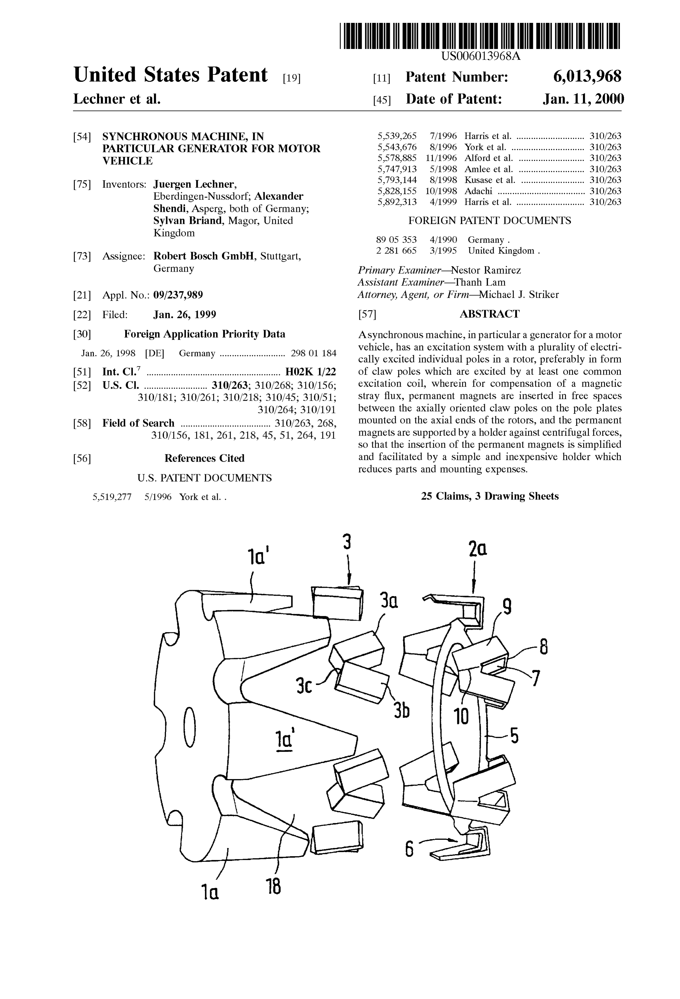
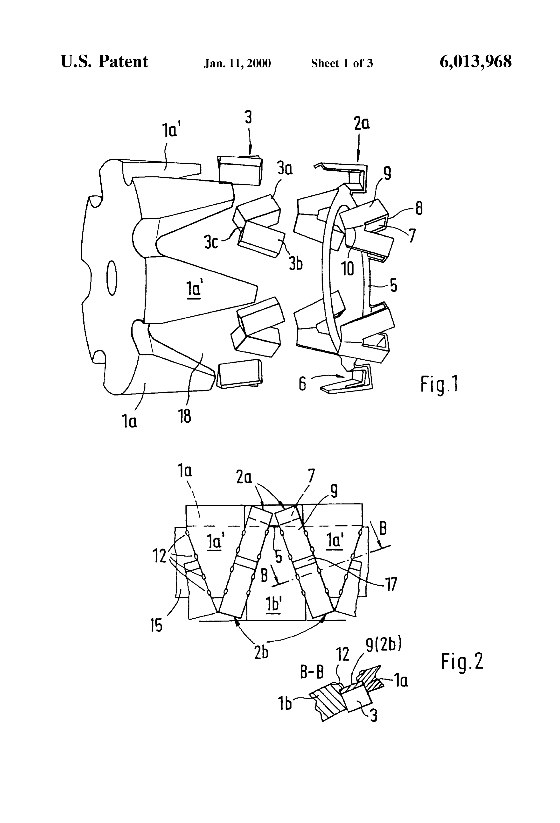
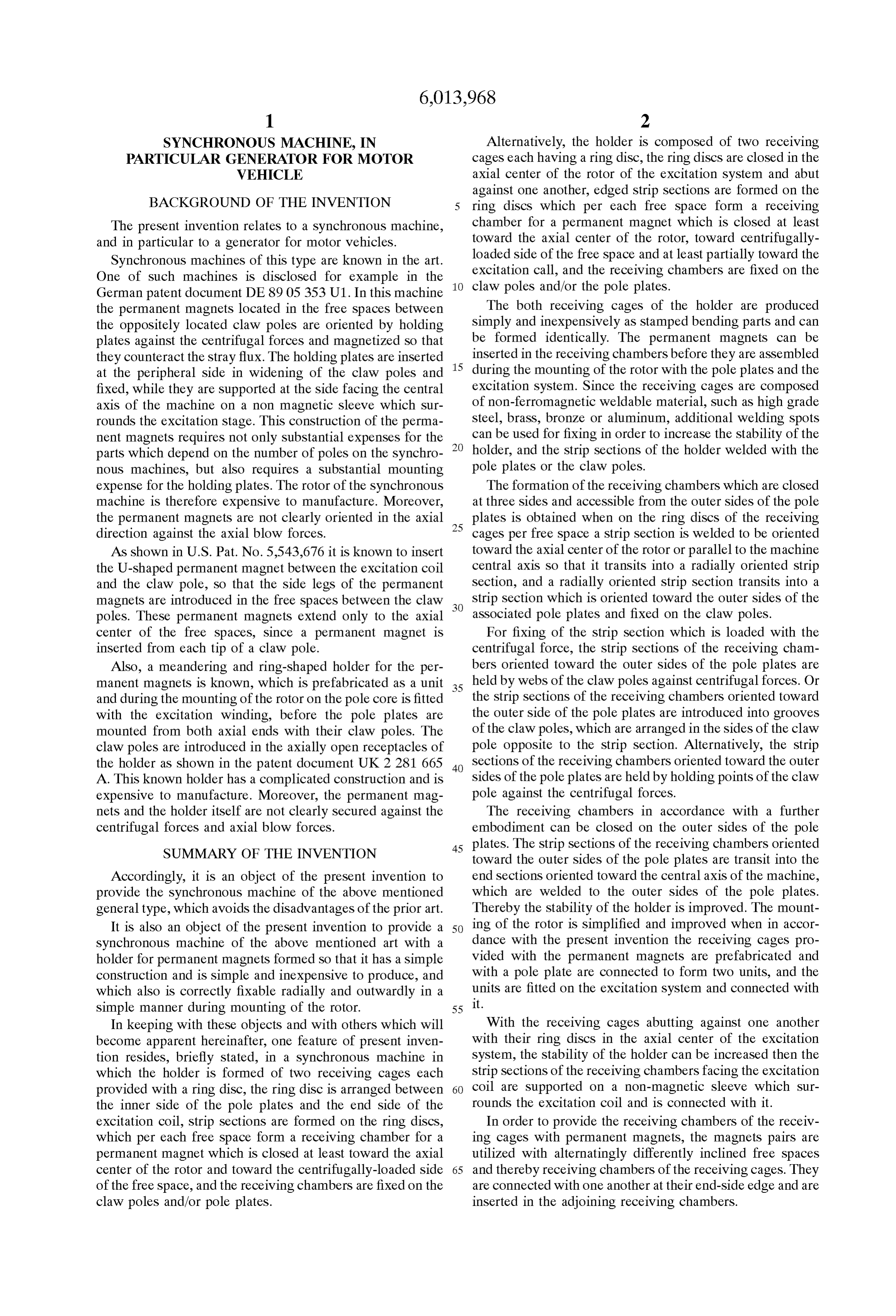
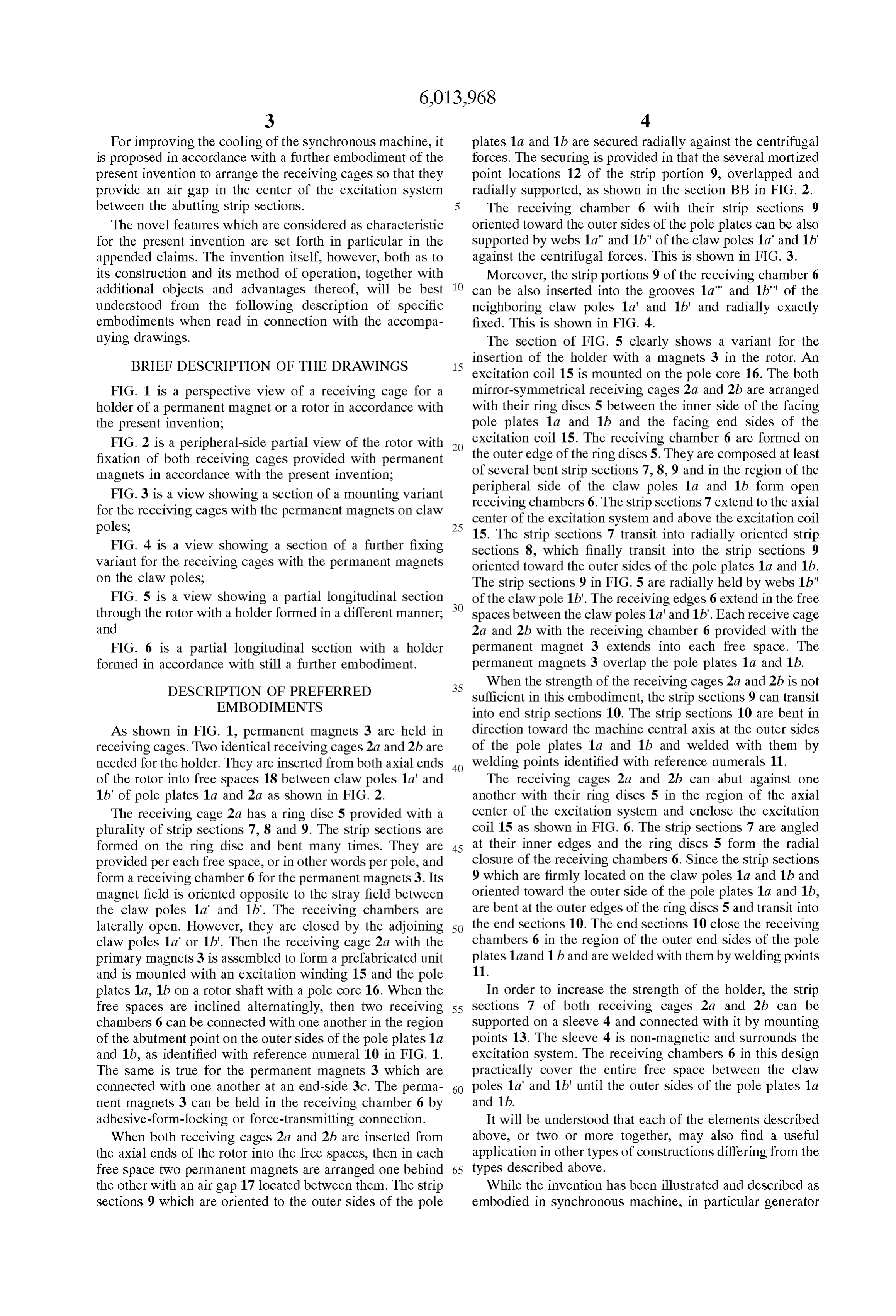
FIG. 1 is a perspective view of a receiving cage for a mirror-symmetrical receiving cages 2a and 2b are arranged holder of a permanent magnet or a rotor in accordance with with their ring discs 5 between the inner side of the facing the present invention; pole plates 1a and 1b and the facing end Sides of the FIG. 2 is a peripheral-side partial view of the rotor with excitation coil 15. The receiving chamber 6 are formed on fixation of both receiving cages provided with permanent the Outer edge of the ring discS 5. They are composed at least magnets in accordance with the present invention; of several bent strip sections 7, 8, 9 and in the region of the FIG. 3 is a view showing a Section of a mounting variant peripheral receiving
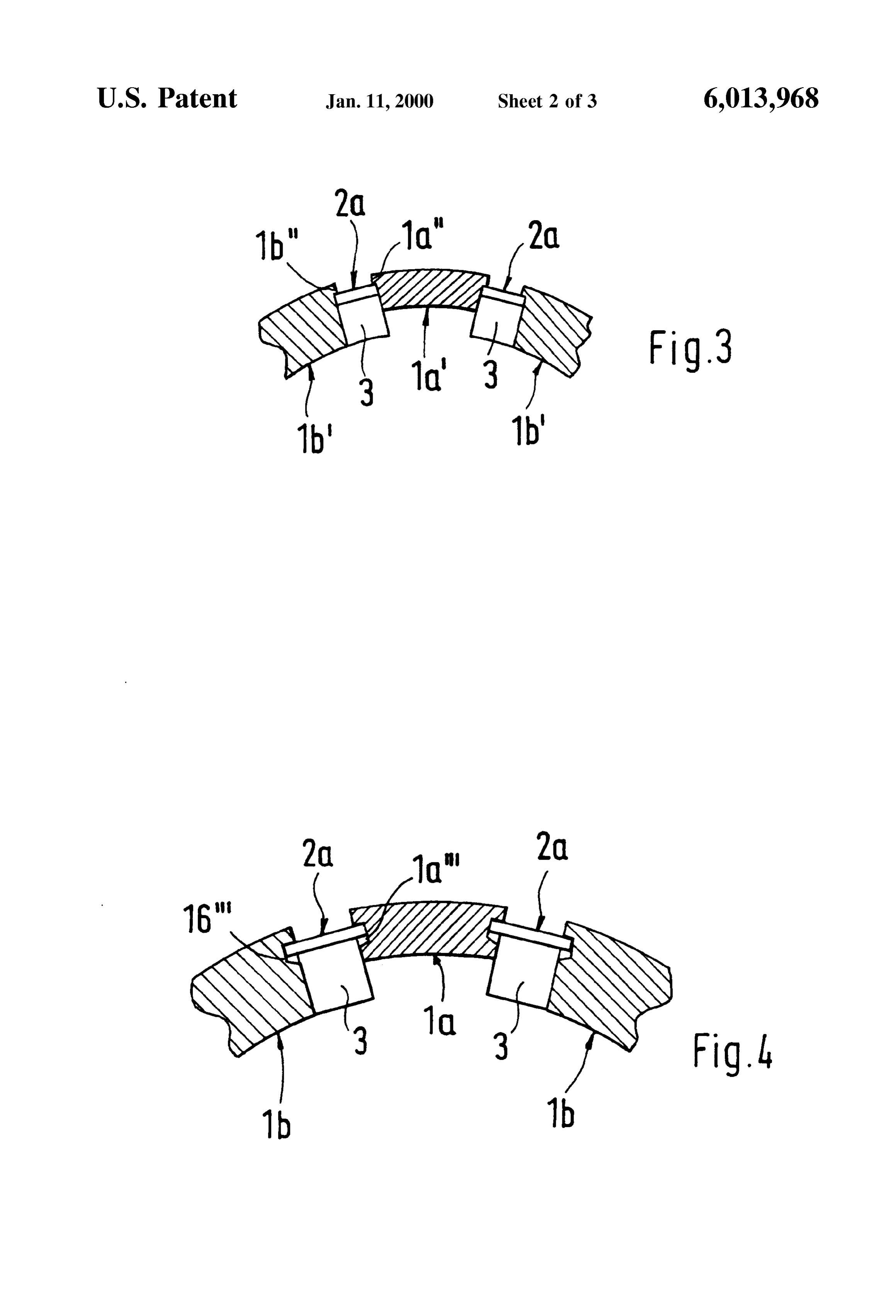
Side of the claw poles 1a and 1b form open chambers 6. The strip sections 7 extend to the axial for the receiving cages with the permanent magnets on claw center of the excitation System and above the excitation coil poles, 25 15. The strip sections 7 transit into radially oriented strip
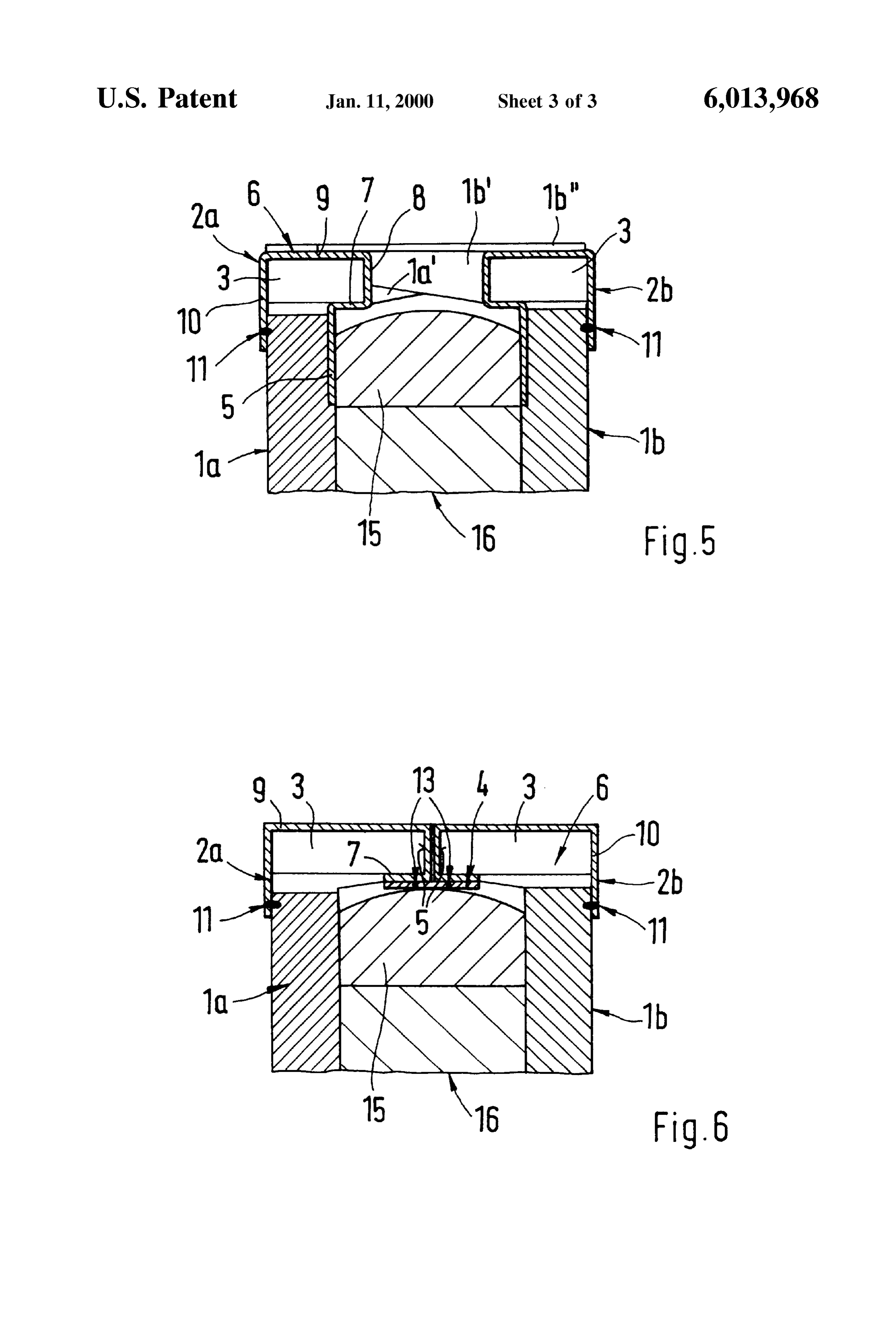
FIG. 4 is a view showing a section of a further fixing sections 8, which finally transit into the strip sections 9 variant for the receiving cages with the permanent magnets oriented toward the outer sides of the pole plates 1a and 1b. on the claw poles, The strip sections 9 in FIG. 5 are radially held by webs 1b." FIG. 5 is a view showing a partial longitudinal Section of the claw pole 1b'. The receiving edges 6 extend in the free through the rotor with a holder formed in a different manner; Spaces between the claw poles 1a' and 1b'. Each receive cage and 2a and 2b with the receiving chamber 6 provided with the FIG. 6 is a partial longitudinal section with a holder permanent magnet 3 extends into each free Space. The formed in accordance with still a further embodiment. permanent magnets 3 overlap the pole plates 1a and 1b. DESCRIPTION OF PREFERRED 35 When the Strength of the receiving cages 2a and 2b is not
EMBODIMENTS
sufficient in this embodiment, the strip sections 9 can transit into end strip sections 10. The strip sections 10 are bent in
AS shown in FIG. 1, permanent magnets 3 are held in direction toward the machine central axis at the outer sides receiving cages. Two identical receiving cages 2a and 2b are of the pole plates 1a and 1b and welded with them by needed for the holder. They are inserted from both axial ends 40 welding points identified with reference numerals 11. of the rotor into free spaces 18 between claw poles 1a' and The receiving cages 2a and 2b can abut against one 1b' of pole plates 1a and 2a as shown in FIG. 2. another with their ring discS 5 in the region of the axial The receiving cage 2a has a ring disc 5 provided with a center of the excitation System and enclose the excitation plurality of strip sections 7, 8 and 9. The strip sections are coil 15 as shown in FIG. 6. The strip sections 7 are angled formed on the ring disc and bent many times. They are 45 at their inner edges and the ring discs 5 form the radial provided per each free Space, or in other words per pole, and closure of the receiving chambers 6. Since the Strip Sections form a receiving chamber 6 for the permanent magnets 3. Its 9 which are firmly located on the claw poles 1a and 1b and magnet field is oriented opposite to the Stray field between oriented toward the outer side of the pole plates 1a and 1b, the claw poles 1a' and 1b'. The receiving chambers are are bent at the Outer edges of the ring discS 5 and transit into laterally open. However, they are closed by the adjoining 50 the end sections 10. The end sections 10 close the receiving claw poles 1a' or 1b'. Then the receiving cage 2a with the chambers 6 in the region of the outer end Sides of the pole primary magnets 3 is assembled to form a prefabricated unit plates 1aand 1 band are welded with them by welding points and is mounted with an excitation winding 15 and the pole 11.
plates 1a, 1b on a rotor shaft with a pole core 16. When the In order to increase the Strength of the holder, the Strip free Spaces are inclined alternatingly, then two receiving 55 Sections 7 of both receiving cages 2a and 2b can be chambers 6 can be connected with one another in the region Supported on a sleeve 4 and connected with it by mounting of the abutment point on the outer Sides of the pole plates 1 a points 13. The sleeve 4 is non-magnetic and Surrounds the and 1b, as identified with reference numeral 10 in FIG. 1. excitation System. The receiving chambers 6 in this design The same is true for the permanent magnets 3 which are practically cover the entire free Space between the claw connected with one another at an end-side 3c. The perma 60 poles 1a' and 1b' until the outer sides of the pole plates 1 a nent magnets 3 can be held in the receiving chamber 6 by and 1b.
adhesive-form-locking or force-transmitting connection. It will be understood that each of the elements described When both receiving cages 2a and 2b are inserted from above, or two or more together, may also find a useful the axial ends of the rotor into the free Spaces, then in each application in other types of constructions differing from the free Space two permanent magnets are arranged one behind 65 types described above.
the other with an air gap 17 located between them. The strip While the invention has been illustrated and described as sections 9 which are oriented to the outer sides of the pole embodied in Synchronous machine, in particular generator
Page 7
S 6 for motor vehicle, it is not intended to be limited to the 10. A Synchronous machine as defined in claim 1, wherein details shown, Since various modifications and structural Said receiving cages is provided with Said permanent mag changes may be made without departing in any way from the nets are prefabricated and connected with a respective one of Spirit of the present invention. Said pole plates So as to form two units fitted on Said Without further analysis, the foregoing will so fully reveal excitation System and connected with the later. the gist of the present invention that others can, by applying 11. A Synchronous machine as defined in claim 1, wherein current knowledge, readily adapt it for various applications the free Spaces and Said receiving chambers of Said receiving without omitting features that, from the Standpoint of prior cages are alternatingly differently inclined, Said permanent art, fairly constitute essential characteristics of the generic or magnets being assembled in magnet pairs which are con Specific aspects of this invention. nected with one another at an end-side edge and inserted in What is claimed as new and desired to be protected by Said12.receiving A chambers abutting against one another.
Synchronous machine as defined in claim 1, wherein letters patent is Set forth in the appended claims. Said receiving cages are arranged So that they leave an air We claim:
1. A Synchronous machine formed as a generator for a gap Strip in a center of Said excitation System between said third
Sections which abut against one another.
motor vehicle, comprising a rotor; an excitation System 15 13. A Synchronous machine formed as a generator for a including a plurality of electrically excited individual poles motor vehicle, comprising a rotor; an excitation System provided in Said rotor and formed as claw poles excited by including a plurality of electrically excited individual poles at least one excitation coil; a plurality of permanent magnets provided in Said rotor and formed as claw poles excited by inserted in free Spaces between Said claw poles, Said poles at least one excitation coil; a plurality of permanent magnets having pole plates on which said permanent magnets are inserted in free Spaces between Said claw poles, Said poles arranged; a holder which Supports and holds Said permanent having pole plates on which Said permanent magnets are magnets, Said holder being composed of two non-magnetic arranged; a holder which Supports and holds Said permanent receiving cages each having a ring disc, Said ring disc being magnets, Said holder being composed of two non-magnetic arranged between inner Sides of pole plates and end Sides of receiving cages each provided with a ring disc, Said ring disc Said excitation coil located between Said pole plates, said 25 in an axial center of Said rotor Surrounding Said excitation ring disc being provided with a plurality of bent Strip coil and abutting against one another, Said ring disc having Sections forming a receiving chamber for each free Space for a bent Strip Section which per each free Space forms a at least one of Said permanent magnets Such that it is closed receiving chamber for at least one of Said permanent mag at least toward an axial center of Said rotor and toward a nets which receiving chamber is closed toward the axial centrifugally-loaded Side of the free Space, Said receiving center of Said rotor, toward a centrifugally-loaded Side of the chambers being fixed on elements Selected from the group free Space and at least partially toward Said excitation coil, consisting of Said claw poles, Said pole plates, and both. Said receiving chambers being fixed on elements Selected 2. A Synchronous machine as defined in claim 1, wherein from the group consisting of claw poles, pole plates, and Said receiving cages are formed as Stamped bending parts of both.
a non-magnetic, weldable material Selected from the group 35 14. A Synchronous machine as defined in claim 13, consisting of high grade Steel, brass, bronze and aluminum. wherein Said receiving cages are formed as Stamped bending 3. A Synchronous machine as defined in claim 1, wherein parts of a non-magnetic, weldable material Selected from the Said Strip Sections include a first Strip Section provided on group consisting of high grade Steel, brass, bronze and each of Said ring disc of Said receiving cages per each free aluminum.
Space, a Second Strip Section which is oriented radially 40 15. A synchronous machine as defined in claim 13, outwardly and into which said first Strip Sections transits, wherein Said Strip Section includes a first Strip Section and a third axial Strip Section into which Said Second Strip provided on each of Said ring discs of Said receiving cages Sections transmits and which is oriented toward either Sides per each free Space, a Second Strip Section which is oriented of facing ones of Said pole plates and fixed on Said claw radially outwardly and into which Said first Strip Sections poles. 45 transits and a third axial Strip Section into which said Second 4. A Synchronous machine as defined in claim 3, wherein Strip Sections transmits and which is oriented toward either Said first Strip Section is oriented toward the axial center of Sides of facing ones of Said pole plates and fixed on Said claw Said rotor. poles.
5. A Synchronous machine as defined in claim 3, wherein 16. A synchronous machine as defined in claim 15, Said first Strip Sections is oriented parallel to a central axis of 50 wherein Said first Strip Section is oriented toward the axial the Synchronous machine. center of Said rotor.
6. A Synchronous machine as defined in claim 3, wherein 17. A synchronous machine as defined in claim 15, Said claw poles have webs, Said third Strip Sections being wherein Said first Strip Sections is oriented parallel to a held against centrifugal forces by Said webs. central axis of the Synchronous machine. 7. A Synchronous machine as defined in claim 3, wherein 55 18. A synchronous machine as defined in claim 15, Said claw poles have grooves provided in Sides of Said claw wherein Said claw poles have webs, Said third Strip Sections poles which face Said third Strip Sections, Said third Strip being held against centrifugal forces by Said webs. Sections being inserted in Said grooves. 19. A synchronous machine as defined in claim 15, 8. A Synchronous machine as defined in claim 3, wherein wherein Said claw poles have grooves provided in Sides of Said third Strip Sections of Said receiving chambers are held 60 Said claw poles which face Said third Strip Sections, Said third on an edge of Said claw poles against centrifugal forces by Strip Sections being inserted in Said grooves. mortised holding points. 20. A synchronous machine as defined in claim 15, 9. A Synchronous machine as defined in claim 3; and wherein Said third Strip Sections of Said receiving chambers further comprising end Sections which are oriented toward a are held on an edge of Said claw poles against centrifugal central axis of the Synchronous machine and welded with 65 forces by mortised holding points.
outer end Sides of Said pole plates, Said third Strip Sections 21. A Synchronous machine as defined in claim 15; and transiting into Said end Sections. further comprising end portions which are oriented toward a
Page 8
central axis of the Synchronous machine and welded with 24. A Synchronous machine as defined in claim 13, outer end Sides of Said pole plates, Said third Strip Sections wherein the free Spaces and Said receiving chambers of Said transiting into Said end portions. receiving cages are alternatingly differently inclined, Said 22. A Synchronous machine as defined in claim 13, permanent magnets being assembled in magnet pairs which wherein Said receiving cages provided with Said permanent are connected with one another at an end-side edge and magnets are prefabricated and connected with a respective inserted in Said receiving chambers abutting against one one of Said pole plates So as to form two units inserted on another.
Said excitation System and connected with the later. 25. A Synchronous machine as defined in claim 1, wherein 23. A Synchronous machine as defined in claim 13; and Said receiving cages are arranged So that they leave an air further comprising a non-magnetic sleeve which Surrounds gap in a center of Said excitation System between said third Said excitation coil, Said Strip Sections including first Strip Strip Sections which abut against one another. Sections which are Supported in Said Sleeve and connected with said sleeve. k k k k k
Provenance
- Collection
- Cited prior art
- Original PDF
- patentimages.storage.googleapis.com →
- Filed
- 1999-01-26
- Pages
- 8
- Method
- pdftotext (the PDF's own text layer) + pdftoppm 300dpi page scans
- Source
- Google Patents bibliographic record
- Granted
- 2000-01-11
- Inventors
- Juergen Lechner; Alexander Shendi; Sylvan Briand; Robert Bosch GmbH
- Transcribed from
- patentimages.storage.googleapis.com →