patent · US3363910
Fluid mounted shaft seal
16 January 1968
Page 1
Drawing sheet — no readable text.
Page 2
United States Patent Office 3,363,910 Patented Jan. 16, 1968
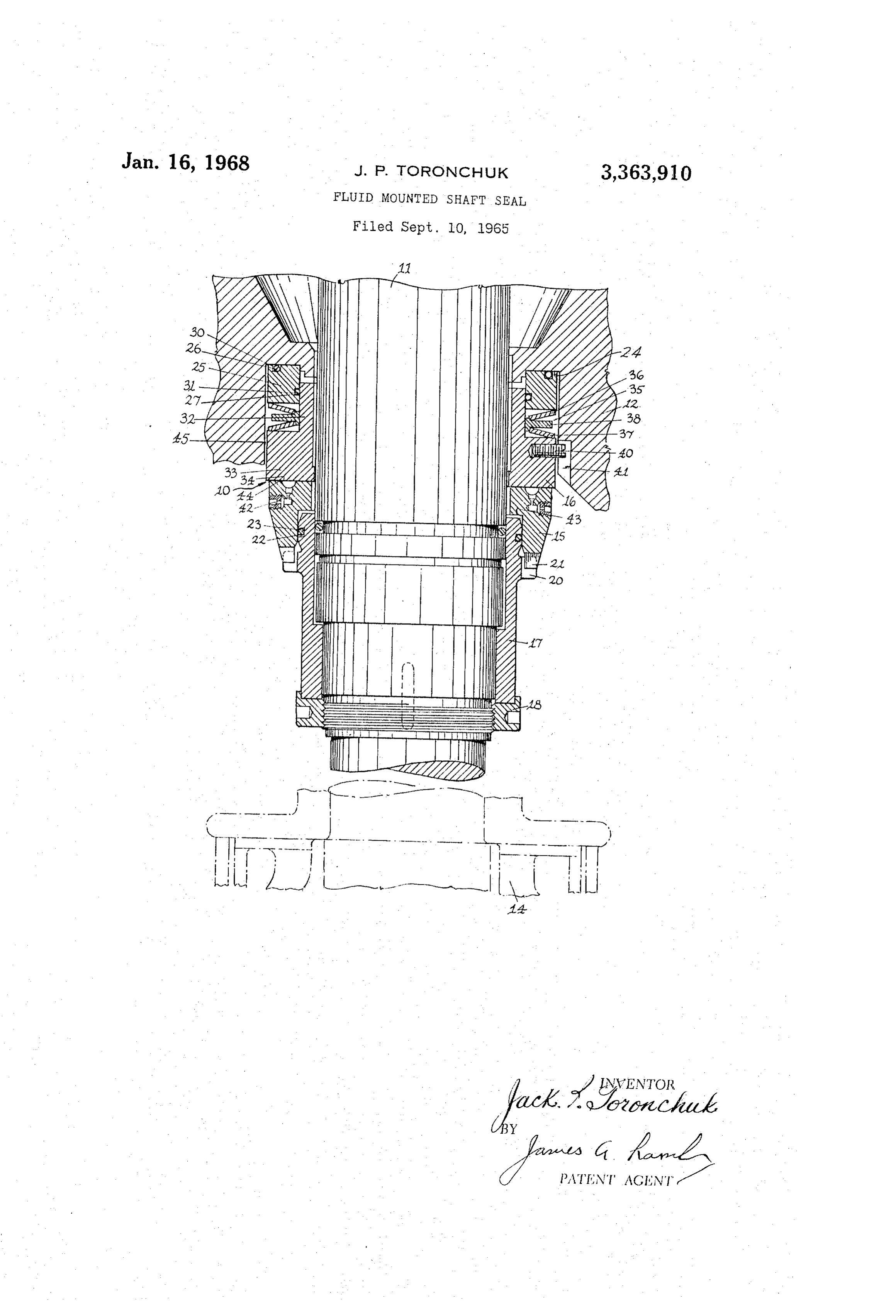
3,363,910 High pressure seals usually are designed to have one FLUID MOUNTEA). SHAFT SEAL of the sealing members subjected to the high pressure Jack P. Toronchuk, Toronto, Ontario, Canada, assignor in such a manner that the high pressure is used to force to Atomic Energy of Canada Limited, Ottawa, Ontario, that sealing member towards the opposing sealing mem Canada,
Act a company under the Atomic Energy Controi 5 ber. A sealing member which relies only on the pressure
Claims priority, application Canada, July 13, 1965, of the fluid to press it towards an opposing sealing mem ber is referred to as a fluid backed seal and may be said 935,685 to "float.” Such a seal has many desirable features. One 3 Claims. (CI. 277-5) feature is that the force with which the floating sealing O member is urged towards the opposing sealing member bears a relationship to the pressure of the surrounding
ABSTRASCT OF THE DESCLOSURE fluid (i.e., to the fluid being pumped). The higher the A shaft seal for a high presure pump having a station pumping pressure, the greater is the sealing force urging ary Sealing member capable of limiting axial and tilting the fluid backed sealing member towards the rigid seal movement and having a rotary sealing member with an ing member. Another feature is that the designer of such inner cylindrical surface spaced from the shaft and an a seal can calculate the forces involved on the fluid backed annular member on the shaft projecting outwards with a seal member and readily determine the loading. Another Sealing ring at its apex engaging the inner cylindrical feature of the fluid backed sealing member or floating Surface on the rotary sealing member. This permits the 20 member is that it is easily designed to be capable of lim rotary sealing member to move longitudinally and tilt ited tilting and axial movement. Yet another advantage, With respect to the shaft. and an important one in high pressure pumps is that a mumminstage orcala fluid backed sealing member is not subject to the deforma tion of its supporting structure as is a mechanically
This invention relates to high pressure seals for rotating 25 backed or rigidly mounted sealing member. It should be shafts. noted that in a high pressure pump, forces of considerable It is customary to provide the rotary shaft of a pump magnitude are required to press the Sealing members to with a mechanical seal to prevent the liquid being pumped gether. These forces should be applied or distributed from leaking out of the pump along the shaft. Such seals evenly over the sealing members if there is to be no dis usually comprise two engaging collars or sealing mem 30 tortion or deformation of the sealing member. Even a bers. One sealing member rotates with the shaft and the very smail deformation may affect the sealing surface. other is stationary relative to the shaft. The matching With a fluid backed sealing member the forces are dis or sealing surfaces of the sealing members are pressed tributed hydrostatically and evenly and distortion is kept together during operation of the pump so that they form to a minimum. Where a sealing member is backed by a a Sea mechanical engagement with a casing or a spring it is It is very desirable when the sealing members are in 35 more difficult to ensure that the forces are distributed stalled that they be installed with the sealing surfaces evenly and no deformation occurs. perpendicular to the axis of rotation. A thin film of liquid It is desirable to use in a high pressure pump, sealing is normally present between the sealing surfaces during members which are both capable of limited tilting and operation and this prevents actual contact between the axial movement, and to use in a high pressure pump seal Sealing surfaces. If there is any misalignment caused by 40 ing members which are both fluid backed or substantially tilting error or by deformation of the seal then actual fluid backed. However, it appears no one has designed a contact may occur between the sealing surfaces over a high pressure seal which has such features. part of the cycle of rotation of the shaft. This generates It is therefore an object of this invention to provide unwanted heat as well as causing rapid deterioration of 45 a high pressure seal of novel design having a rotary seal the sealing surfaces. ing member and a stationary sealing member both To avoid misalignment problems, it is known to have capable of limited axial and tilting movement. one of the sealing members rigidly mounted and the other It is another object of this invention to provide a high sealing member mounted to permit not only axial move pressure seal having one sealing member which is ment, but movement of the plane of the sealing surface fluid backed and another sealing member which is with reference to a plane at right angles to the axis of 50 substantially fluid backed at operating pressures. Totation (hereinafter referred to as tilting movement). These and other objects and advantages of the inven For example, the rotating sealing member may be fixed tion will appear from the following description taken in to the shaft while the stationary sealing member may be conjunction with the accompanying drawings in which: mounted to permit the necessary limited axial and tilting 55 The single figure is a longitudinal sectional view through movement and may be spring biased towards the rotating a high pressure seal according to the invention. member to form the seal. Referring to the drawing, a seal indicated generally as These known seals will permit a certain amount of 56) is mounted between a rotary shaft 1 and a casing 12. misalignment caused by errors in manufacture or in in The casing 52 defines a high pressure chamber in which stallation. If both the sealing members could be mounted 60 a pump impeller 4 rotates. The impeller 14, of which to permit tilting movement, and preferably to permit both only a part is indicated in the drawing in phantom, is se tilting movement and axial movement, then misalignment cured to and is driven by shaft 1. The opposite end of errors would become less of a problem. Low pressure shaft seals have been developed in which both the sealing shaft 11 is arranged to be driven in a suitable manner. members are supported on flexible, hollow, elastic O-rings 65 The seal 10 separates the high pressure chamber of to provide a degree of axial, lateral and tilting movement the pump from the low pressure portion. That is, the seal to both sealing members. However, this design cannot be prevents leakage along the shaft from a high pressure applied directly to high pressure seals. Also, it is dif region to a region where there is a lower pressure. The ficult to determine the distribution of loading forces on seal () comprises a rotary sealing member 15 which is the sealing surfaces in such a seal, and being able to de loosely fastened to and rotates with shaft il, and a sta termine the distribution and degree of loading is im 70 tionary sealing member 36 which is loosely fastened to portant in evolving a satisfactory seal design. the interior of casing 12. A shaft sleeve 17 is keyed to
Page 3
shaft 11 and is retained on shaft by a nut 8. Thus the pressure liquid acts to provide an upwardly directed force. sleeve 17 and nut 13 rotate with shaft 1. The sleeve 17 is A portion of the high pressure chamber defined by cas provided with one or more slots indicated at 20 while the from22theconstitutes ing region of a constantly open passage 45 leading the lateral surface on the rotary seal rotating sealing member 15 is provided with mating lugs 2 which are received in slots 28. The engagement be 5 ing member 5 to seating recess 35 so that the high pres. sure also is present in seating recess 35. As was previous tween the walls of slots 20 and lugs 22 causes rotary seal ly explained, the O-ring seals 30 and 31 prevent leakage ing member 15 to rotate with sleeve 7 and shaft ii. from the region of seating recess 35. The sealing mem Sleeve 17 has a peripheral groove or slot 22 around the ber 6 also has a lateral surface extending outwardly from upper end (as shown). The sleeve 7 is bevelled on either side of slot 22 so that the slot 22 is at a slight crest. That O cylindrical fining one portion 32 to end portion 33 substantially de boundary of seating recess 35. Again, this is, the shaft sleeve 7 is tapered to a smaller diameter lateral Surface is intended to mean a surface having a on each side of slot 22. An O-ring 23 in slot 22 prevents lateral component such that the high pressure acting on leakage of fluid between sleeve 7 and rotary sealing the lateral surface results in a force directed towards the member 15. Because of the bevelling, adjacent slot 22, the rotary Sealing member 15 (downwards in the drawing). Sealing member 15 has a degree of tilting movement which The sealing members 15 and 16 are made so that the does not affect the seal provided by O-ring 23. The sealing member 15 has a limited longitudinal or axial movement effective lateral surface of sealing member 15 is slightly greater than the effective lateral surface of sealing mem in addition to tilting movement. ber 6. This means that the downwardly directed (as in The casing 12 is provided with a formed recess 24 which holds the stationary sealing member assembly. A 20 the the drawing) force on sealing member 16 resulting from high pressure is slightly less than the upwardly di back up ring 25 is seated in recess 24 and has a groove rected force on sealing member 5 resulting from the or slot 26 extending around an end face thereof and a Same high pressure. In some circumstances, it is conven groove or slot 27 extending around the inner surface ient to have the difference in lateral surfaces about 5% thereof. These slots 26 and 27 hold O-rings 30 and 31, re So that the downwardly directed force is 95% of the up Spectively. The O-ring 30 is to prevent leakage past the Wardly directed force. This percentage may vary widely end of back up ring 25, and the O-ring 35 is to prevent depending on the circumstances. The springs 36 and 37 leakage between back up ring 25 and stationary sealing Inake up the 5% difference in force to provide a balance member 6. between the upwardly directed and downwardly directed The sealing member 16 has a cylindrical portion 32 and forces.
a larger end portion 33 which terminates in sealing sur As the pressure in the pump builds up both the up face 34. The back up ring 25 and the end portion 33 de Wardly and downwardly directed forces increase but the fine a Spring seating recess 35. This recess 35 is shown upwardly directed force increases slightly more than the with a spring 36, a spring 37 and a spacer 38 mounted therein. While two springs are shown to provide a force downwardly directed force resulting from the fluid pres urging Stationary sealing member 16 away from back up 3. 5 Sure. As a result the sealing members 15 and 16 move up ring 25, it will be apparent that a single spring could be Wards compressing Springs 36 and 37 until the spring force with the downwardly directed pressure created force used. A set Screw 40, or alternately a pin, is received in the side of end portion 33 of sealing member 16. A slot equals the upwardly directed pressure created force. Per haps an example will illustrate the operation more clearly.
4 is provided in the inner wall of casing 12 to receive the end of Screw 40. The screw 46 and the walls of slot 40 Suppose a pressure of 100 p.s. i. is present in the high 41 cooperate to prevent rotary movement of sealing pressure chamber and that the area of the seal 16, which member 16. when Subject to this pressure provides the downwardly The rotary sealing member 5 is shown as having a (directed Sealing force, is 4.75 sq. in., while the area of seal 15 which when Subject to this pressure provides the up plurality of orifices 42 extending from the side of sealing Wardly member 15 to a terminating sealing surface 44. These directed sealing force is 5.00 sq. in. Then the orifices provide a self-energizing feature for the seal as pressure causes a downward force of 475 lbs. and an up is known in the art. However, it is not necessary that there Ward force of 500 lbs. The springs 36 and 37 are com be such orifices for the present invention. The present in pressed to provide the balance of 25 lbs. and the seal is in equilibrium. If the pressure should increase to 1000 p.s. i., vention is effective on seals where the sealing members are not provided with such orifices, as well as on self 50 this new pressure would result in a downward force of energizing Seals as shown in the drawing. 4750 lbs. and an upward force of 5000 lbs. The sealing The Sealing mernbers 5 and 6 may be made of any members 15 and 6 will both move upwards and springs material Suited to the operating and environmental condi 36 and 37 will be further compressed until they provide a tions to be encountered. Such materials and their use in downwardly directed force on sealing member 16 of 250 high pressure Seals are known and may for example be 55 lbs. The Seal is then in equilibrium at the new pressure. Steel, bronze, carbon or like material. It will be seen that the sealing members move axially The operation of a seal assembly according to the in to maintain equilibrium and that they are both capable Vention will now be described with reference to a seal of tilting movement to maintain an even satisfactory having no self-energizing orifices. With the pump at rest Seal. The rotary sealing member 15 is entirely fluid backed the Springs 36 and 37 urge stationary sealing member 16 60 while the stationary sealing member is substantially fluid away from back up ring 25 (downwards in the drawing), backed (perhaps of the order of 95% or more) to keep and the rotary sealing member 15 may move downwards any deformation of the accurately machined sealing sur until shoulder 43 engages the end of shaft sleeve 7. faces to a minimum.
When the pump starts, the pressure begins to build up in Liquid at high pressure is available at the outer side the high pressure chamber and exerts a force on the (farthest from the shaft) of sealing members 15 and 16. exposed surfaces of the sealing members 5 and 16. In That is, liquid at high pressure is present during operation other words, the rotary sealing member 25 has a lateral of the pump at the outer side of the seal where sealing surface generally opposite to the sealing surface, and this surfaces 44 and 34 terminate. A thin film of the liquid lateral Surface is exposed to the increasing pressure. By between sealing surfaces 44 and 34 not only lubricates lateral Surface it is intended to mean a surface having a 70 these Surfaces but provides a force keeping the surfaces lateral component such that the high pressure acting on from actual contact. In the self-energizing seal, shown in the lateral surface results in a force directed towards the stationary sealing member 6 (upwards in the drawing). the drawing, orifices 42 provide a restricted path for liquid In other words, the lateral surface on the rotary sealing to the Sealing Surfaces to promote initial flow and lubrica member has a predetermined area on which the high tion between the sealing surfaces as is well known.
Page 4
It is believed the present invention provides a high 6 pressure seal having improved means for automatic ad apex of said rotary sealing member with respect to justment of the sealing surfaces and having sealing mem said shaft, bers at least substantially fluid backed. keying means engaging said shaft and said rotary seal claim: . ing member for causing said rotary sealing member 1. In a shaft seal for a high pressure pump, to rotate with said shaft and permitting limited longi a housing defining a high pressure chamber, tudinal and tilting movement of said rotary sealing a rotary shaft extending into said housing and having member with respect to said shaft, a portion of a first diameter, said rotary sealing member having a sealing sur a rotary sealing member having an inner right cylin 10 face at one end thereof defining a plane substan drical surface of a second diameter greater than said tially at right angles to the axis of said inner first diameter positioned over said portion of said cylindrical surface and having towards the other shaft, end thereof a first lateral surface exposed to means extending outwardly from said portion of said said high pressure chamber, shaft and having at its outward extremity an annu a stationary sealing member positioned over said shaft lar apex adjacent said inner cylindrical surface, and having a sealing surface at one end thereof de resilient sealing means mounted in said apex engaging fining a plane substantially at right angles to its axis said inner cylindrical surface to form a seal per and having part way towards the other end thereof a mitting longitudinal movement and tilting movement second lateral surface exposed to said high pressure about said apex of said rotary sealing member with 20 chamber, respect to said shaft, the sealing surface of said stationary sealing mem keying means engaging said shaft and said rotary seal ber being positioned adjacent and facing the ing member for causing said rotary sealing member sealing surface of said rotary sealing member, to rotate with said shaft and permitting longitudinal resilient sealing means engaging the walls of said hous and tilting movement of said rotary sealing memebr 25 ing and the other end of said stationary sealing mem with respect to said shaft, ber to form a seal, said rotary sealing member having a sealing sur keying means engaging said housing and said stationary face at one end thereof defining a plane substan sealing member for preventing rotation of said sta tionary sealing member, tially at right angles to the axis of said inner the area of said second lateral surface being less cylindrical surface and having towards the other 30 than the area of said first lateral surface provid end thereof a first lateral surface exposed to said ing a resultant force caused by the pressure in high pressure chamber, said high pressure chamber in a direction to a stationary sealing member positioned over said shaft wards the stationary sealing member, and and having a sealing surface at one end thereof de spring means engaging said housing and said stationary fining a plane substantially at right angles to its axis sealing member providing on said stationary sealing and having part way towards the other end therof member a force equal to said resultant force respon a second lateral surface exposed to said high pres sive to compression of said spring means by said sure chamber, resultant force.
the sealing surface of said stationary sealing mem 40 ber being positioned adjacent and facing the 3. In a shaft seal for a high pressure pump having sealing surface of said rotary sealing member, a housing defining a high pressure chamber, resilient sealing means engaging the walls of said hous a rotary shaft extending into said housing, ing and the other end of said stationary sealing mem a stationary sealing member positioned on said shaft ber to form a seal, having a sealing surface at one end thereof defining keying means engaging said housing and said stationary 45 a plane Substantially at right angles to the axis of sealing member for preventing rotation of said sta said shaft and having at least part way towards the tionary sealing member, other end therof a first lateral surface, the area of said second lateral surface being less resilient means providing a seal between said housing than the area of said first lateral surface provid and said stationary sealing member while permitting ing a resultant force caused by the pressure in 50 limited axial and tilting movement, said high pressure chamber in a direction to Spring means engaging said housing and said stationary wards the stationary sealing member, and Sealing member to provide a force in a first axia spring means engaging said housing and said stationary direction, sealing member providing on said stationary sealing a rotary sealing member positioned on a portion of member a force equal to said resultant force respon Said shaft having a sealing surface at one end there sive to compression of said spring means by Said re of adjacent to and facing the sealing surface on said Sultant force.
2. In a shaft seal for a high pressure pump, stationary sealing member and having towards the a housing defining a high pressure chamber, other end thereof a second lateral surface, 60 the improvement comprising a rotary shaft extending into said housing and having a portion of a first diameter, said rotary sealing member having an inner right a rotary sealing member having an inner right cylin cylindrical Surface of a diameter greater than drical surface of a second diameter greater than said the diameter of said portion of said shaft, first diameter positioned over said portion of said 65 means extending outwardly from said portion of said shaft and having at its outward extremity an annular shaft, annular means secured to said portion of said shaft and apex adjacent said inner cylindrical surface, and extending outwardly to form at its outward extremity resilient Sealing means mounted in said apex engaging an apex adjacent said inner cylindrical surface, and said inner cylindrical surface to form a seal per having a peripheral groove at said apex, 70 mitting longitudinal and tilting movement of said a resilient sealing ring mounted in said groove and rotary Sealing member with respect to said shaft, projecting therefrom to engage said inner cylindri said first and second lateral areas both being ex cal surface forming a seal permitting longitudinal posed to the high pressure chamber providing movement and limited tilting movement about said 75 fluid backing for said rotary and stationary seal ing members, the area of said first lateral sur
Page 5
7 References Cited face being less than the area of said second lateral surface whereby pressure in said high UNITED STATES PATENTS pressure chamber presses the sealing surface on 2,479,265 8/1949 Roshong ------------ 277-27 said rotary and stationary sealing members to 2,639,204 5/1953 Terry ------------ 277.91 X gether with a net resultant force in a second 5 3,239,232 3/1966 Andresen ------------- 277-5 axial direction opposite said first direction and said force in said first direction matching said SAMUEL ROTHBERG, Primary Examiner. net resultant force.
Provenance
- Collection
- Cited prior art
- Original PDF
- patentimages.storage.googleapis.com →
- Filed
- 1965-09-10
- Pages
- 5
- Method
- pdftotext (the PDF's own text layer) + pdftoppm 300dpi page scans
- Source
- Google Patents bibliographic record
- Granted
- 1968-01-16
- Inventors
- Jack P Toronchuk; Atomic Energy of Canada Ltd AECL
- Transcribed from
- patentimages.storage.googleapis.com →