patent · US4289970
Wind powered electrical generator
15 September 1981
Page 1 — bibliographic record
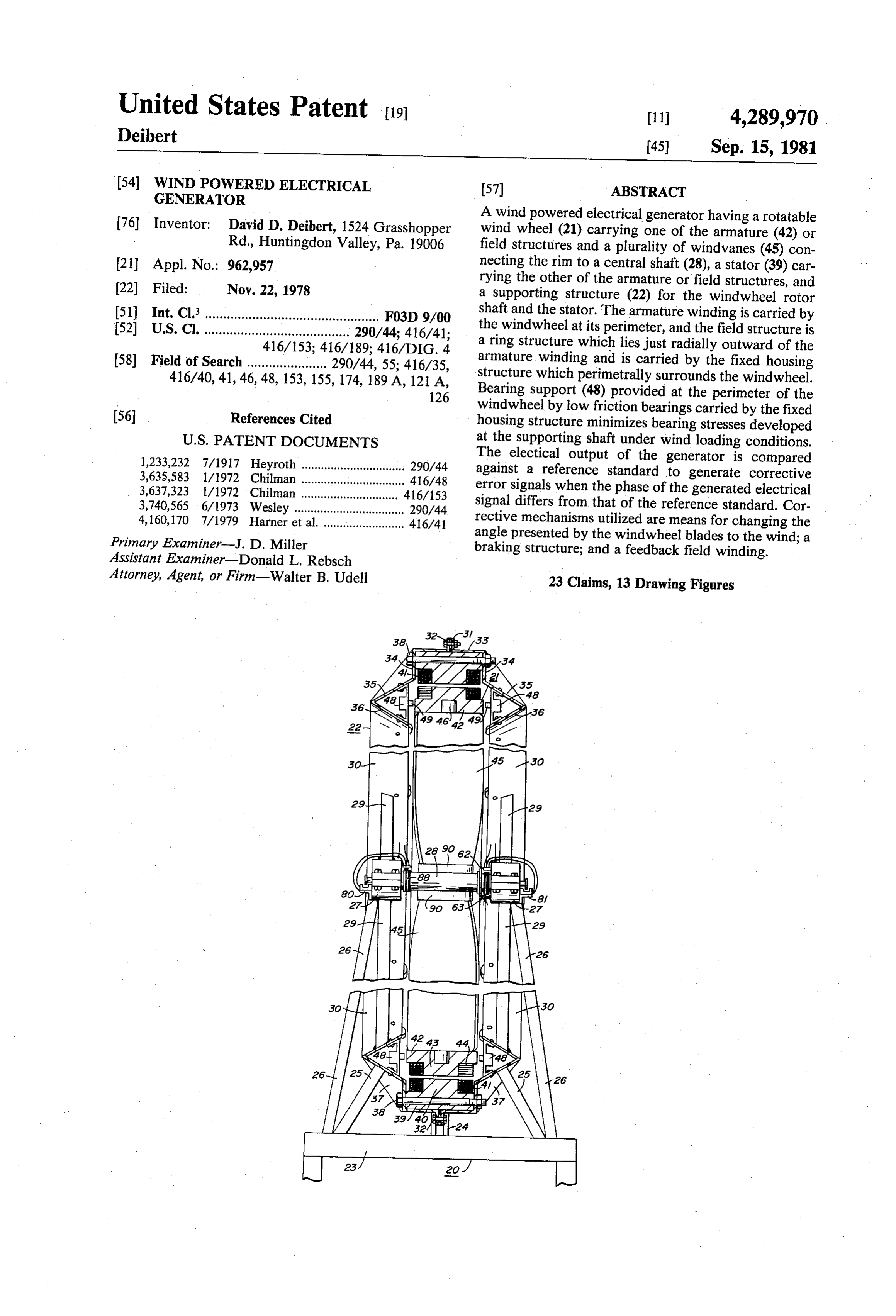
United States Patent to 11 4,289.970 Deibert
54 WIND POWERED ELECTRICAL 57) ABSTRACT
GENERATOR
A wind powered electrical generator having a rotatable 76 Inventor: David D. Deibert, 1524 Grasshopper wind wheel (21) carrying one of the armature (42) or Rd., Huntingdon Valley, Pa. 19006 field structures and a plurality of windvanes (45) con 21 Appl. No.: 962,957 necting the rim to a central shaft (28), a stator (39) car 22 Filed: Nov. 22, 1978 rying the other of the armature or field structures, and a supporting structure (22) for the windwheel rotor 51) Int. Cl. ................................................ F03D 9/00 shaft and the stator. The armature winding is carried by 52 U.S. Cl. ........................................ 290/44; 416/41; the windwheel at its perimeter, and the field structure is 416/153; 416/189: 416/DIG. 4 a ring structure which lies just radially outward of the 58) Field of Search ...................... 290/44, 55; 416/35, armature winding and is carried by the fixed housing 416/40, 41, 46,48, 153, 155, 174, 189A, 121 A, structure which perimetrally surrounds the windwheel. 126 Bearing support (48) provided at the perimeter of the
windwheel by low friction bearings carried by the fixed housing structure minimizes bearing stresses developed
1,233,232 7/1917 Heyroth ................................ 290/44
The electical output of the generator is compared 3,635,583 1/1972 Chilman ..... ... 416/48 against a reference standard to generate corrective 3,637,323 1/1972 Chilman ..... 416/153 error signals when the phase of the generated electrical 3,740,565 6/1973 Wesley ....... ... 290/44 signal differs from that of the reference standard. Cor 4, 160,170 7/1979 Harner et al... ... 416/41 rective mechanisms utilized are means for changing the Primary Examiner-J. D. Miller angle presented by the windwheel blades to the wind; a Assistant Examiner-Donald L. Rebsch braking structure; and a feedback field winding. Attorney, Agent, or Firm-Walter B. Udell 23 Claims, 13 Drawing Figures
Aziz
Page 2
Drawing sheet — no readable text.
Page 3
Drawing sheet — no readable text.
Page 4
Drawing sheet — no readable text.
Page 5
Drawing sheet — no readable text.
Page 6
operating conditions. As a consequence, a far less mas
WIND POWERED ELECTRICAL GENERATOR sive windwheel structure is utilizable which is respon sive to relatively light winds and is considerably less
This invention relates to sinusoidal alternating cur 5 Additionally, the electrical output of the wind pow rent electrical generators, and more particularly relates ered and generator according to the invention is monitored compared against a reference standard to generate to electrical generators in which the prime mover for the generating mechanism is wind power. error signals when the phase of the generated electrical
BACKGROUND ART
signal differs from that of the reference standard. The 10 error signals so generated are utilized to control correc
All of the prior art discovered by search in the U.S. tive mechanisms for reducing the error voltage towards Patent and Trademark Office is as follows: zero. These corrective mechanisms which form also part of the invention are means for changing the angle
U.S. Pat, No, Patentee Granting Date presented by the windwheel blades to the wind in order 15 to appropriately increase or decrease the velocity of the 889,883 E. J. Johnson June 2, 1908 windwheel; the use of a braking structure to slow down
1,334,485 C. D. Clipfell et al Mar. 23, 1920 the windwheel when appropriate; and when an electri 1,352,960 A. H. Heyroth Sept. 14, 1920 cal field winding is utilized, for controlling current in a
G. Manikowske et al
H. Honnef
feedback field winding.
2,144,719 H. Gefficken Jan. 24, 1939 In the illustrated form of the invention, the armature 3,740,565 N. G. Wesley June 19, 1973 winding is carried by the windwheel at its perimeter and is shown as a wave winding which produces high
The field of search was voltages that may be subsequently transformed to lower
voltages at higher currents. A lower voltage winding, 25 such as a lap winding, may also be used if desired. The
U.S. Class 415, subclasses 2,4 field structure is also a ring structure which lies just U.S. Class 416, subclasses 3, 90A, 197A radially outward of the armature winding and is carried DISCLOSURE OF INVENTION by the fixed housing structure which perimetrally sur Wind powered electrical generators have been de- 30 rounds the windwheel. This configuration minimizes signed in the past and are a continuing subject of inter clearance changes between the armature and the field est as sources of power because they are non-polluting also structures due to wind loading of the windwheel, and and do not require use of fossil fuels or nuclear sources to thehelps to mechanically stabilize the windwheel due magnetic field configuration. None of the known as prime movers for driving the electrical generator prior art discloses any of the foregoing features of the system. Most forms of wind powered electrical genera 35 invention.
tors utilize windvane structures in the form of wheels rotating about a central shaft axis in which the rotation The electrical output from the wind driven electrical of the wheel is mechanically transmitted to a conven generator may be used as direct auxiliary electrical tional type electrical generator for producing an electri power or may be used as a source of energy to be con cal output. verted into other forms for storage, such as in a heat Other forms of wind powered electrical generators retaining medium or in electrical form by charging have been devised in the past in which the armature large scale storage batteries. A primary object of the invention is to provide a winding is located about the perimeter of the wind driven wheel and the field structure is located proxi novel wind powered electrical generator in which the mate to the armature. It is this latter form of wind 45 armature and field structures are located at the periph driven electrical generator construction with which the ery of a wind drivable wheel, and in which the wind present invention is concerned. The structures of this wheel is of relatively light mass construction and is type disclosed by the known prior art have serious mechanically stabilized at its periphery. technical drawbacks in that there is provided no struc Another object of the invention is to provide a novel tural support for the wind driven wheel at its perimeter, 50 wind powered electrical generator as aforesaid which and since the windwheels contemplated for use may be includes means for stabilizing the voltage and frequency on the order of twenty to fifty feet in diameter, the of the generator output by controlling the rotational bearing stresses developed at the supporting shaft under speed of the windwheel and the excitation of the field possible conditions of wind loading are so large that the windings.
required physical structure becomes economically un 55 A further object of the invention is to provide a novel feasible. This same wind loading problem reflects out wind powered electrical generator as aforesaid wherein ward into a requirement for extremely high structural the means for controlling the rotational speed of the strength in the windwheel which results in high mass windwheel includes means for controlling the pitch of structures which militate against effective movement of the windwheel vanes, and means for electrically mag the windwheel under normally available wind condi- 60 netically or mechanically loading the windwheel to tions. The structures of the windwheels must necessar draw off power.
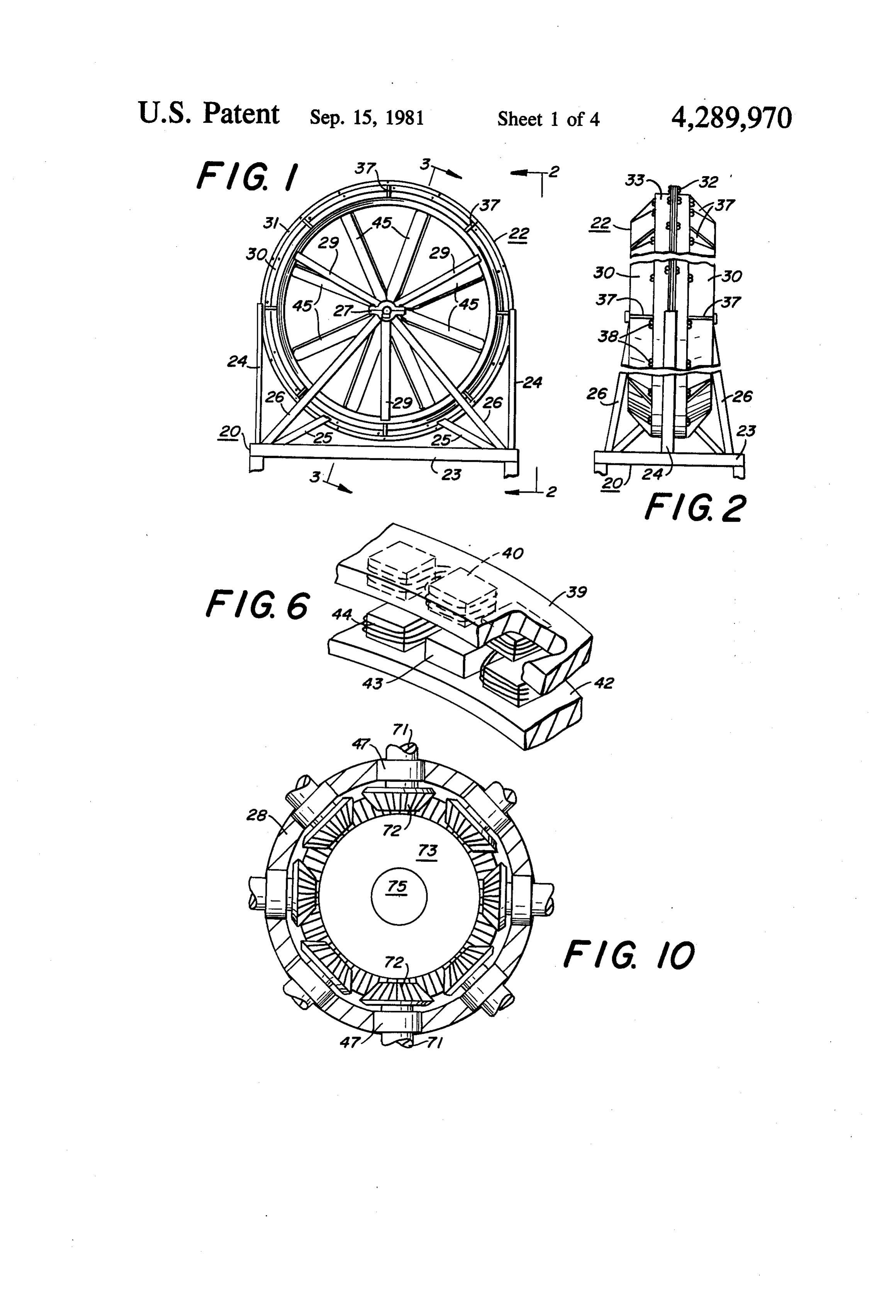
ily be designed to withstand very high wind gust forces BRIEF DESCRIPTION OF DRAWINGS even though the average wind velocity will be very much lower than the gust velocities. FIG. 1 is a front elevation of the wind powered elec The present invention overcomes this problem in past 65 trical generator according to the invention; structures by providing a fixed strong structure extend FIG. 2 is a broken view side elevation of the genera ing perimetrally around the windwheel and providing tor according to the invention as would be seen when low friction lateral support for the windwheel under viewed along line 2-2 of FIG. 1;
Page 7
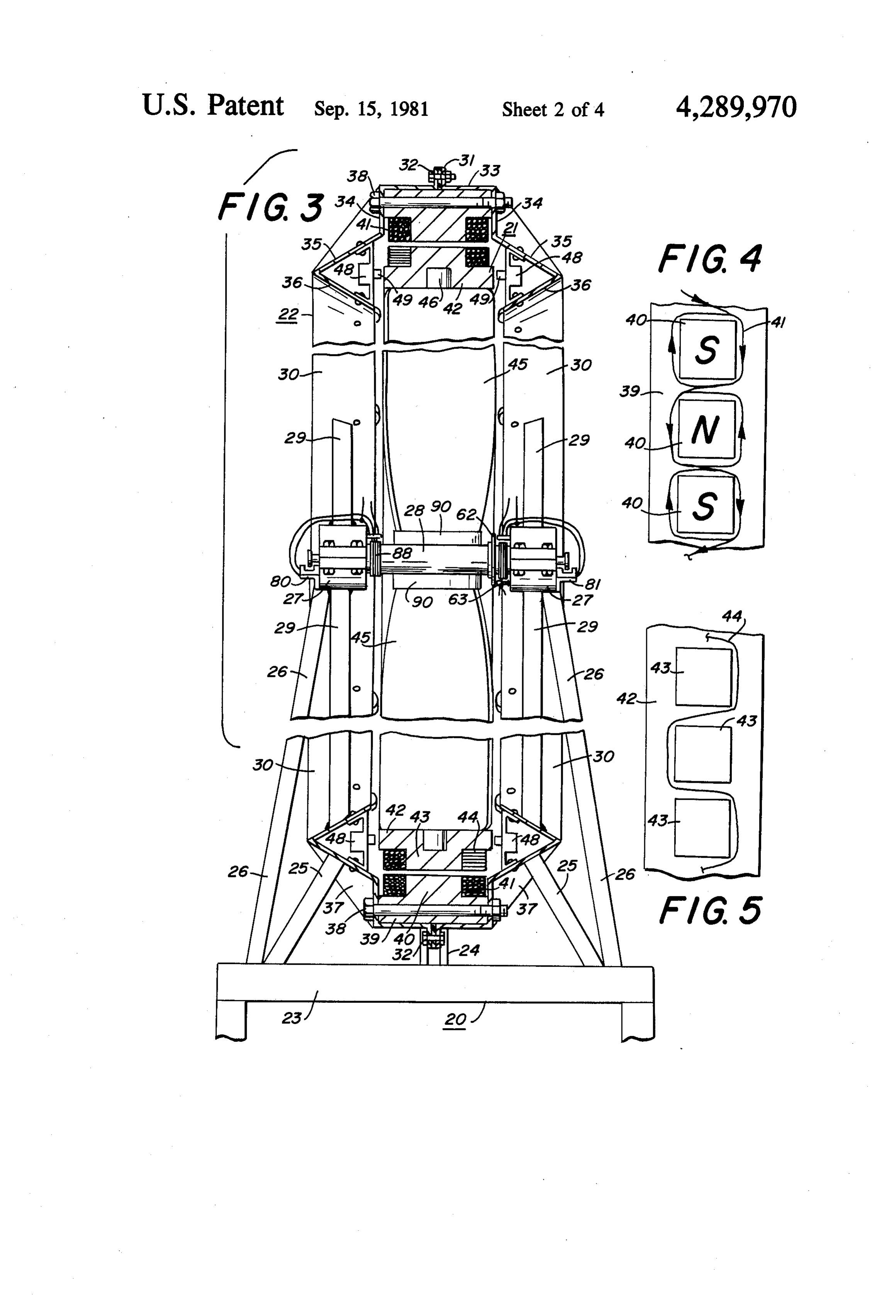
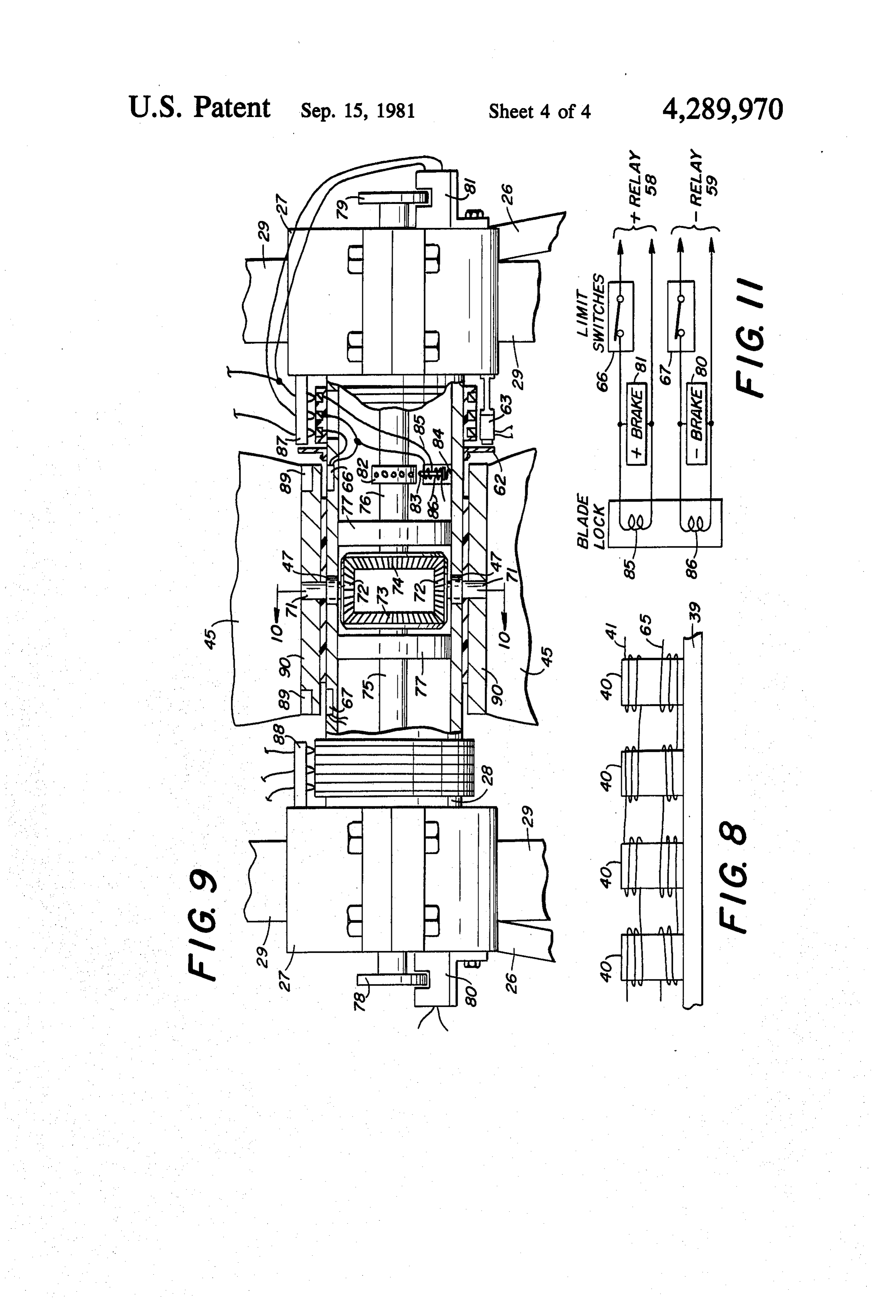
FIG. 3 is an enlarged broken sectional view of the inward of the rim flanges 31, this channel consisting of generator according to the invention as would be seen an outer base wall 33 and a pair of spaced apart opposite along line 3-3 of FIG. 1; side walls 34. Extending in opposite directions axially FIG. 4 is a diagrammatic plan view of a portion of the outwardly from the open end of each of the sidewalls 34 field winding structure showing the winding directions; is a radially inwardly facing annularly extending wall 35 FIG. 4A is an alternative showing to that of FIG. 4; which reverses and turns back axially and radially in FIG. 5 is a diagrammatic plan view of a portion of the wardly as the annularly extending walls 36. The annular armature winding structure illustrating a wave winding; walls 35 and 36 direct the air flow to provide a stream FIG. 5A is an alternative showing to that of FIG. 5; lining minimal wind resistance load to the wind. FIG. 6 is a fragmentary perspective view of portions 10 Formed or otherwise rigidly secured to the annular of the windwheel armature structure and field struc walls 35 and sidewalls 34 are the rigidifying triangular ture; gussets 37.
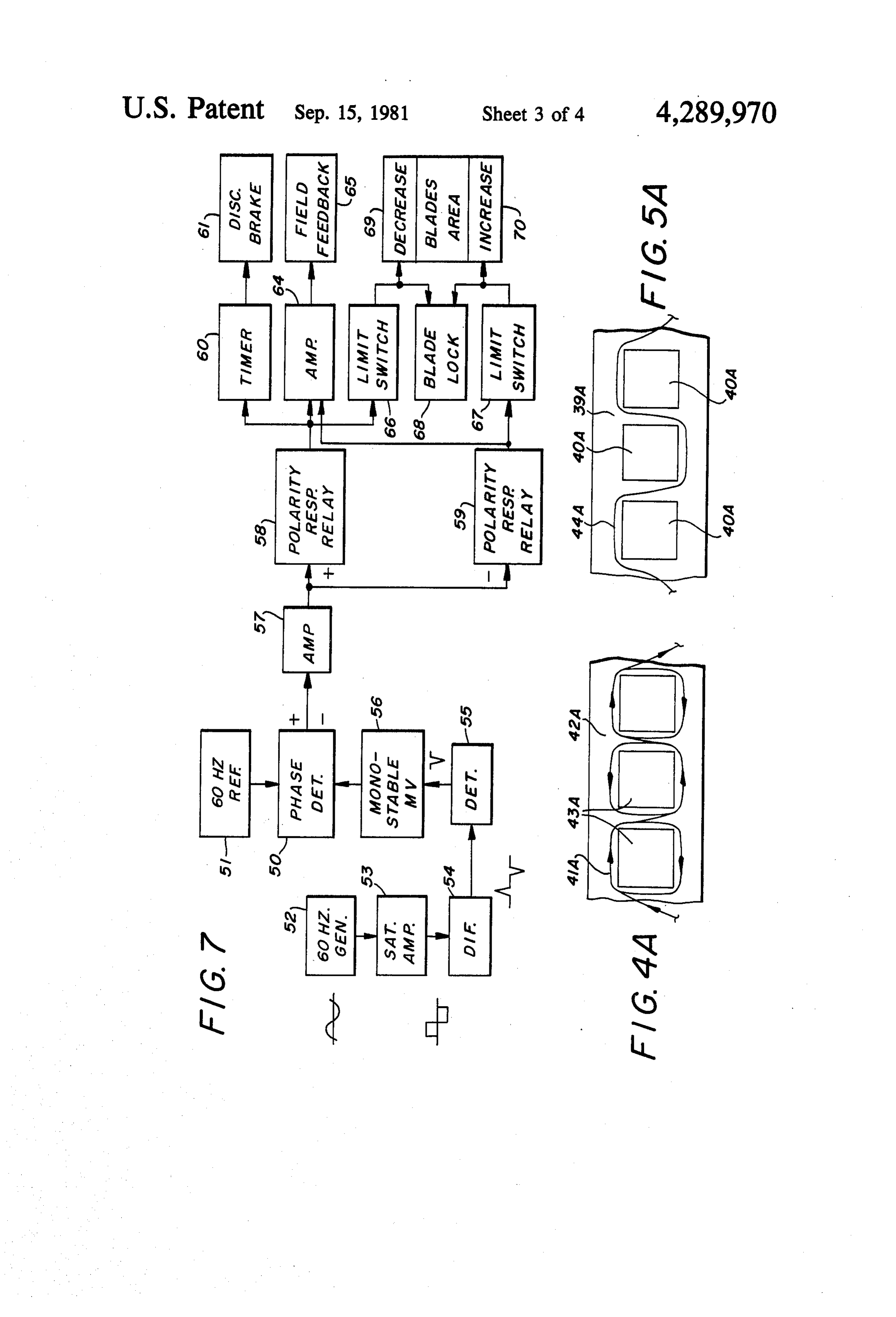
FIG. 7 is a functional block diagram of the system for Secured within the open channel formed by the controlling the output of the electrical generator ac shroud base walls 33 and sidewalls 34 by means of the cording to the invention; 15 bolts and nuts 38 is an annular field poles base plate 39 FIG. 8 is a fragmentary side view of the field struc carrying a large number of radially inwardly extending ture showing both main field and feedback windings; field poles 40 about which are wound the generator FIG. 9 is an enlarged view of the support shaft region field windings designated generally as 41. The diagram of the generator shown in FIG. 3 with some parts being matic showing of FIG. 4 illustrates the manner in which in section to disclose details of the shaft brake and wind 20 the main field winding 41 is wound, the winding direc vane rotation mechanisms; tion being illustrated by the arrowheads. Accordingly, FIG. 10 is a cross-sectional view through the wind if the arrowheads also designate the direction of field vanes differential structure as would be seen when current flow, it will be observed that an alternating viewed along line 10-10 of FIG. 9; and series of south and north poles is created about the FIG. 11 is a schematic diagram of a part of the electri 25 circular inner perimeter of the field pole structure. cal control circuit for the windvane rotation system. Disposed immediately radially within the inside pe BEST MODE FOR CARRYING OUT THE rimeter of the circular annular field pole structure is the INVENTION generator armature structure consisting of the armature base plate 42 from which radially outwardly project the
Referring first to FIGS. 1, 2 and 3 there is seen the 30 armature winding support pillars 43 about which are overall structure of the wind powered electrical genera wound the armature winding 44. This structure is tor according to the invention. The structure consists shown diagrammatically in the showing of FIG. 5. The basically of a structural support designated generally as annular armature base plate 42 is positionally mechani 20, a windwheel 21 carrying the generator armature, cally stabilized by a plurality of windvanes 45 the outer and a supporting shroud 22 peripherally surrounding 35 ends of which are journalled for rotation in bearings 46 the windwheel 21 and carrying the generator field which are set into the armature base plate 42, the oppo structure, both the windwheel21 and support shroud 22 site ends of the windvanes 45 being similarly journalled being mechanically carried by the structural support 20. for rotation in bearings 47 set into the central generator The structural support 20 includes a base or platform 23 shaft 28, as best seen in the showing of FIG. 9. FIG. 6 upwardly from which extend to supporting engagement 40 shows a diagrammatic fragmentary perspective view of with the shroud 22 a pair of side support struts 24 and the field poles and armature structures of the generator. bottom struts 25. Also secured to and extending up Wind loading stress on the shaft bearings 27 is greatly wardly from the base 23 are two pairs of struts 26 which reduced by utilizing a plurality of low friction rolling converge at the windwheel axis on opposite sides of the bearings carried by the supporting shroud 22 in the windwheel to carry the bearings 27 within which is 45 space between the annular walls 35 and 36, the bearings journalled opposite ends of the windwheel shaft 28. being secured to those walls and designated as 48. Each Also secured to and extending radially outward from bearing 48 has a low friction rolling portion 49 project the shaft bearings 27 on each side of the windwheel are ing toward the side face of the armature base plate 42, as three additional shroud struts 29 which are rigidly se best seen in the showing of FIG. 3. The clearance be cured to the shroud 22, as for example by welding or 50 tween the armature base plate 42 and the bearings 49 is any other suitable means. The base or platform 23 is arranged so that under light wind loadings there will be carried at the top of a tower, not shown, by a mecha no contact between the two, but under heavy wind nism which affords rotation of the generator structure loadings tending to cause the armature to move in a about a vertical axis for a proper orientation with re downwind direction, the armature base plate or ring 42 spect to the then prevailing winds. The means for ef 55 will engage the rolling bearings 49 and relieve the tor fecting such orientation of the generator structure does isional load from the shaft bearings 27. not constitute a part of the present invention. FIGS. 8,9,10 and 11 illustrate some of the detailed The supporting shroud 22 consists of a pair of identi mechanisms for stabilizing the voltage and frequency of cal annular oppositely facing rims 30 each having an the alternating current output of the generator, but outwardly radially extending flange 31, which flanges, 60 before referring thereto for the mechanical and electri as best seen in FIGS. 2 and 3, abut one another about cal details, it will be more conducive to an understand the entire periphery of the shroud and are secured to ing of the invention to first refer to the functional logic gether as by bolts and nuts 32. The shroud rim flanges diagram of FIG. 7. The philosophy of FIG. 7 is to 31 are disposed within a slot portion of the side support sample the output of the wind driven electrical genera struts 24 which latter are in the form of channel struc 65 tor and compare its frequency with that of a reference tures. waveform to generate an error signal when the fre The secured together shroud rims form a three sided quency of the wind driven generator varies from that of open rectangular annular channel immediately radially the reference standard, generating a positive error sig
Page 8
nal when the wind driven generator is generating a cause if the brake were to be applied until the error waveform of higher frequency than the reference, and signal diminished to zero, the decreasing momentum of generating a negative error signal when the frequency the wheel could cause the rotational velocity to slow of the wind driven generator output waveform is lower beyond the zero error signal generation point and than that of the reference waveform. The error signals 5 would result in a negative error signal. The disc brake is are then utilized to actuate mechanisms for returning therefore applied intermittently by means of the timer the generated output waveform toward the reference 60. If desired, sophisticated systems could be utilized to standard frequency by automatically actuating the de sample the rate of change of the error signal and control vices to be described.
Referring now to FIG. 7 there is shown a phase de 10 theThe brake accordingly.
tector 50, one input of which comes from a reference both thesecond automatically operating system utilizes standard, in this case designated as a 60 Hertz reference the amplifier 64 and positive negative error signals and includes and field feedback winding 65. The '51. The other input to the phase detector is initiated by field feedback winding is also shown in FIG. 8 which the output signal of the wind driven electrical genera tor, shown as a 60 Hertz generator 52. The frequency of 15 illustrates the winding 65 being wound in opposition to the waveform generated by the wind driven electrical the main field winding 41. The field feedback system is generator is determinable from the following formula: not directed toward controlling the frequency, but rather toward controlling the amplitude of the output signal. A consequence of increased or decreased gener 20 ator rotational velocity will be increased or decreased where voltage amplitude at the output, and this is also not a f=frequency in Hertz desired condition. By decreasing or increasing the field Np=number of field poles excitation, and hence the magnetic flux, the generated RPM = revolutions per minute of windwheel output voltage can be reduced or increased. Design of This could for example be achieved by a windwheel 25 the field feedback winding and associated driving cir having a field structure of one hundred eighty poles and cuitry for maintaining substantially constant output is a rotating at forty revolutions per minute. For a wind function of the electrical and mechanical design of a wheel of twenty feet diameter, there would be approxi particular windwheel generator and the parameters mately three field poles per foot of circumference. The associated with such a structure. output of the wind driven electrical generator 52 is 30 The third automatically operating system is also a sampled and the sample used to drive a saturating ampli system for controlling the velocity of the windwheel fier 53 to square the waveform, this waveform then and is a system for automatically changing the pitch of being differentiated in differentiator 54 and passed the windvanes in the windwheel. When a positive error through a detector 55 to generate a trigger pulse for signal is present, indicating too high a rotational veloc triggering monostable multi-vibrator 56 which pro duces the second signal into the phase detector 50. 35 ity of the windwheel, the pitch of the blades of the windvanes is decreased to reduce the drive on the wind
If the frequency of the wind driven electrical genera tor 52 is the same as that of the reference standard 51, wheel. Conversely, when the error signal generated is then the phase detector will produce no error voltage wheel, theindicating negative, too low a velocity of the wind since no corrective steps need be undertaken. If how 40 matically increased toblades pitch of the of the windvanes is auto thereby increase the driving ever the frequencies of the reference standard and the force on the windwheel which is generated by the wind. wind driven electrical generator differ, the phase detec This system is shown diagrammatically in FIG. 7 in tor will produce a positive or negative error signal which the outputs of the relays 58 and 59 respectively which is then increased in power by amplifier 57 and pass through limit switches 66 and 67 to actuate a blade routed to the polarity responsive relays 58 and 59. If the error signal is a positive error signal, relay 58 will re 45 lock 68 to unlock the blades rotation restraint and simul taneously actuate either the blades area decrease mech spond to it, whereas if the error signal is a negative error anism signal relay 59 will respond to it. 69 or the blades area increase mechanism 70. The Considering first the condition of a positive error limit switches 66 and 67 are utilized to limit the degree signal being generated indicating that the windwheel is of rotation of the windvanes blades since there is a point being driven at too fast a speed of rotation, it is neces 50 of maximum blade area and a point of minimum blade sary to reduce the speed to reduce the error voltage area for development of maximum and minimum driv toward zero. Two systems are illustrated for speed ing forces on the windwheel. Since the development of reduction, both or one of which may be utilized either maximum driving force on the windwheel does not simultaneously or in staged sequences as desired. The coincide with the presentation of maximum blade sur first system utilizes the timer 60 and disc brake 61, the 55 face to the wind, there is a point beyond which the disc of the disc brake being shown in FIGS. 3 and 9 as windvanes should not be rotated for the purpose of the element 62 fixedly secured to and rotatable with the developing maximum drive, continued rotation past main shaft 28, while the electrically actuated caliper such a point necessarily resulting in a reduced drive on structure is designated as 63 and is shown fixedly se the windwheel. The function of the limit switches is cured to the shaft bearing structure. Any desired type of 60 therefore to only permit rotation of the blades of the braking structure may be utilized and at any convenient windvanes up to a maximum amount in a given sense point. For example, more effective braking may more and to then disable the blade rotation mechanisms so conveniently be accomplished out at the rim of the that further rotation cannot occur.
windwheel than at the shaft position, but the illustrated The blade lock structure illustrated and to be de structure is shown merely for purposes of illustration. 65 scribed in connection with the showing of FIG.9, main Since the windwheel is characterized by a relatively tains the windvanes locked fixedly in their adjusted large momentum due to its size and mass, it is not de position, whatever it may be under normal driving cir sired to apply the disc brake on a continuous basis be cumstances. When the automatic system functions to
Page 9
change the windvanes blade area, the blade lock mecha Moreover, as for the case of the disc brake 61, it may nism 68 is unlocked so that the windvanes may be ro be desirable or necessary because of inertia forces to tated under control of the appropriate polarity error rotate the windvanes blades intermittently. If such is signal. Rotation of the windvane blades is also permit found to be the case for particular design situations, an ted only so long as the limit switches are closed, and is intermittent timer similar to that illustrated at 60 may be carried out, as also to be subsequently described, in utilized in series with each limit switch, or some other connection with the showing of FIGS. 9,10 and 11, by appropriate device may be used. utilization of a pair of electrically actuated brakes The blade lock device for maintaining the windvanes which independently and non-simultaneously control a blades in a particular pitch position is shown in FIG. 9 differential structure which rotates the blades of the 10 and consists of the collar 82 fixedly secured about shaft windvanes in a manner to be described. 76 which cooperates with a locking pin 83 normally Referring now to FIGS. 9, 10 and 11, it is observed spring loaded into engagement with the collar 82 by that each of the illustrated pair of diametrically opposite means of spring 84. Locking pin 83 is normally engaged windvane blades 45 is rotatable about a longitudinally in one of the number of peripherally extending detent extending central axis by means of blade shafts 71 which 15 sockets spaced about the blade lock collar 82 but is each pass through one of the bearings 47 and have af shown in retracted position in FIG. 9 to permit rotation fixed to their inner ends a pair of pinion gears 72. The of the windvanes blades. Retraction of the locking pin pinion gears are engaged in a differential arrangement 83 is done in solenoid fashion by energization of either with a pair of bevel gears 73 and 74, which latter are one of the windings 85 or 86. The blade lock winding 85 respectively fixedly secured on a pair of shafts 75 and 76 20 and the brake caliper 81 are energized from the polarity which extend through bearing blocks 77 and axially responsive relay 58 through limit switch 66 and slip ring outward through shaft 28 and shaft bearings 27 to termi assembly 87, whereas blade lock winding 86 and brake nate respectively in a pair of disc brake rotors 78 and 79. caliper 80 are energized from polarity responsive relay The rotor 78 cooperates with an electrically actuatable 59 through limit switch 67 and slip ring assembly 88. brake caliper assembly 80 while the rotor 79 cooperates 25 The limit switches 66 and 67 may typically be reed with an electrically actuatable brake caliper assembly type switches mounted at the shaft 28 and actuated by 81. magnets 89 mounted at suitable positions in the circular From FIG. 10 it will be observed that the blade pair discs 90 which constitute a portion of the windvanes shown in FIG. 9 as identified by blade bearings 47 and blade structure proximate to the shaft 28. As the blades shafts 71 is only one pair of blades in the windwheel, 30 45 rotate they approach their limiting positions and and that there are three additional pairs of windwheel rotate the magnets 89 into apposition with the limit blades which each also include a pair of pinion gears switches 66 and 67 as a function of the direction in engaged with the bevel gears 73 and 74. Accordingly, which the blades are rotated. When one of the magnets relative movement of the bevel gears 73 and 74 will 89 reaches its actuating position it causes the associated cause rotation of all of the pinion gears in the wind 35 limit switch to open and thereby deenergizes the associ wheel. Moreover, because of the differential action, ated brake 80 or 81 and the blade lock retracting mecha when pinion gears 73 and 74 counter-rotate with respect nanism. Accordingly, with the brake deemergized no to one another, the diametrically opposite blades of further rotation of the windvanes blades can occur and each windwheel pair will rotate in opposite directions the blade lock is immediately set to prevent undesired with respect to each other as is required. This rotation 40 rotation of the windvanes blades due to wind action. is effected by actuation of either the brakes 80 or 81 but The electrical schematic operation of this system is not both simultaneously. The rotational operation is shown in FIG. 11.
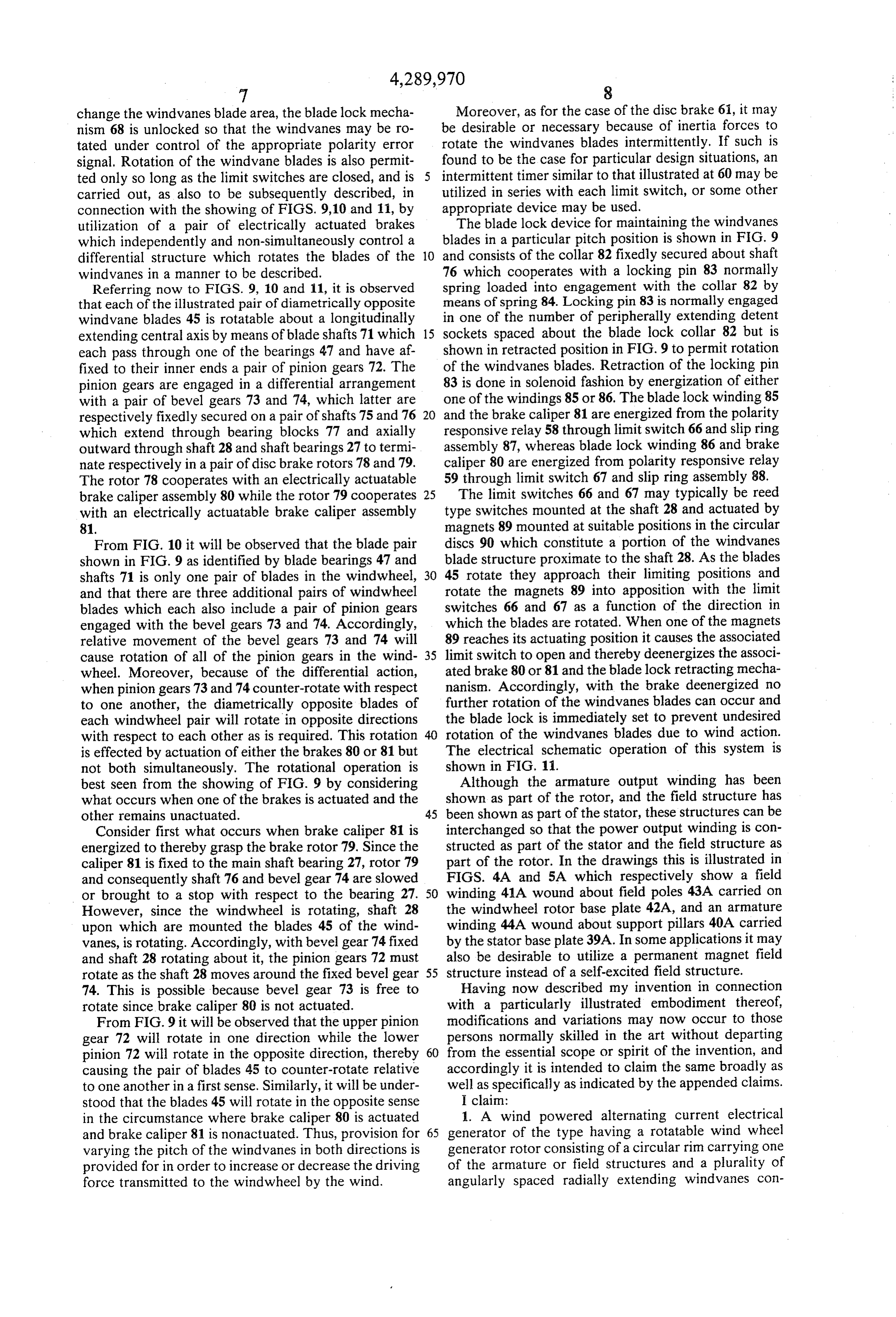
best seen from the showing of FIG. 9 by considering Although the armature output winding has been what occurs when one of the brakes is actuated and the shown as part of the rotor, and the field structure has other remains unactuated. 45 been shown as part of the stator, these structures can be Consider first what occurs when brake caliper 81 is interchanged so that the power output winding is con energized to thereby grasp the brake rotor 79. Since the structed as part of the stator and the field structure as caliper 81 is fixed to the main shaft bearing 27, rotor 79 part of the rotor. In the drawings this is illustrated in and consequently shaft 76 and bevel gear 74 are slowed FIGS. 4A and 5A which respectively show a field or brought to a stop with respect to the bearing 27. 50 winding 41A wound about field poles 43A carried on However, since the windwheel is rotating, shaft 28 the windwheel rotor base plate 42A, and an armature upon which are mounted the blades 45 of the wind winding 44A wound about support pillars 40A carried Vanes, is rotating. Accordingly, with bevel gear 74 fixed by the stator base plate 39A. In some applications it may and shaft 28 rotating about it, the pinion gears 72 must also be desirable to utilize a permanent magnet field rotate as the shaft 28 moves around the fixed bevel gear 55 structure instead of a self-excited field structure. 74. This is possible because bevel gear 73 is free to Having now described my invention in connection rotate since brake caliper 80 is not actuated. with a particularly illustrated embodiment thereof, From FIG. 9 it will be observed that the upper pinion modifications and variations may now occur to those gear 72 will rotate in one direction while the lower persons normally skilled in the art without departing pinion 72 will rotate in the opposite direction, thereby 60 from the essential scope or spirit of the invention, and causing the pair of blades 45 to counter-rotate relative accordingly it is intended to claim the same broadly as to one another in a first sense. Similarly, it will be under well as specifically as indicated by the appended claims. stood that the blades 45 will rotate in the opposite sense I claim:
in the circumstance where brake caliper 80 is actuated 1. A wind powered alternating current electrical and brake caliper 81 is nonactuated. Thus, provision for 65 generator of the type having a rotatable wind wheel varying the pitch of the windvanes in both directions is generator rotor consisting of a circular rim carrying one provided for in order to increase or decrease the driving of the armature or field structures and a plurality of force transmitted to the windwheel by the wind. angularly spaced radially extending windvanes con
Page 10
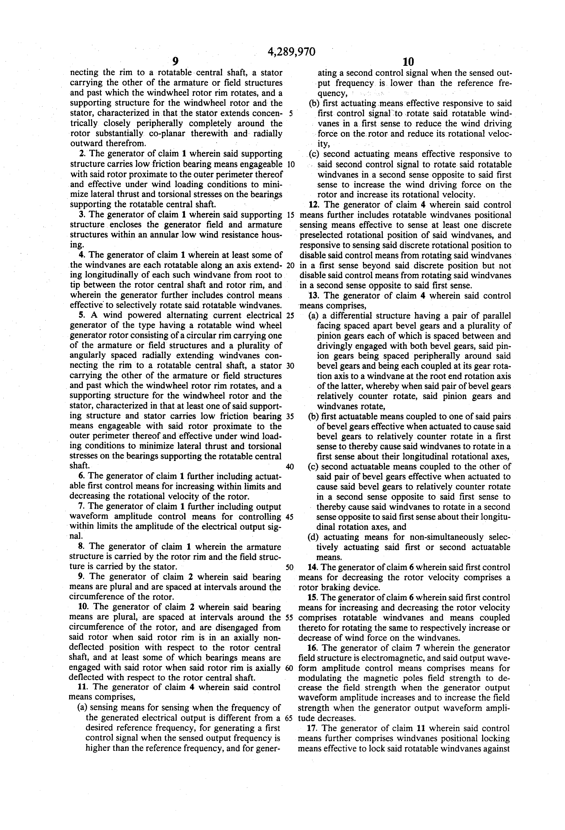
necting the rim to a rotatable central shaft, a stator ating a second control signal when the sensed out carrying the other of the armature or field structures put frequency is lower than the reference fre and past which the windwheel rotor rim rotates, and a quency, . . .
supporting structure for the windwheel rotor and the (b) first actuating means effective responsive to said stator, characterized in that the stator extends concen- 5 first control signal to rotate said rotatable wind trically closely peripherally completely around the vanes in a first sense to reduce the wind driving rotor substantially co-planar therewith and radially force on the rotor and reduce its rotational veloc outward therefrom. ity, 2. The generator of claim 1 wherein said supporting (c) second actuating means effective responsive to structure carries low friction bearing means engageable 10 said second control signal to rotate said rotatable with said rotor proximate to the outer perimeter thereof windvanes in a second sense opposite to said first and effective under wind loading conditions to mini sense to increase the wind driving force on the mize lateral thrust and torsional stresses on the bearings rotor and increase its rotational velocity. supporting the rotatable central shaft. 12. The generator of claim 4 wherein said control 3. The generator of claim 1 wherein said supporting 15 means further includes rotatable windvanes positional structure encloses the generator field and armature sensing means effective to sense at least one discrete structures within an annular low wind resistance hous preselected rotational position of said windvanes, and Ing. responsive to sensing said discrete rotational position to 4. The generator of claim 1 wherein at least some of disable said control means from rotating said windvanes the windvanes are each rotatable along an axis extend- 20 in a first sense beyond said discrete position but not ing longitudinally of each such windvane from root to disable said control means from rotating said windvanes tip between the rotor central shaft and rotor rim, and in a second sense opposite to said first sense. wherein the generator further includes control means . 13. The generator of claim 4 wherein said control effective to selectively rotate said rotatable windvanes. means comprises, 5. A wind powered alternating current electrical 25 (a) a differential structure having a pair of parallel generator of the type having a rotatable wind wheel facing spaced apart bevel gears and a plurality of generator rotor consisting of a circular rim carrying one pinion gears each of which is spaced between and of the armature or field structures and a plurality of drivingly engaged with both bevel gears, said pin angularly spaced radially extending windvanes con ion gears being spaced peripherally around said necting the rim to a rotatable central shaft, a stator 30 bevel gears and being each coupled at its gear rota carrying the other of the armature or field structures tion axis to a windvane at the root end rotation axis and past which the windwheel rotor rim rotates, and a of the latter, whereby when said pair of bevel gears supporting structure for the windwheel rotor and the relatively counter rotate, said pinion gears and stator, characterized in that at least one of said support windvanes rotate, ing structure and stator carries low friction bearing 35 (b) first actuatable means coupled to one of said pairs means engageable with said rotor proximate to the of bevel gears effective when actuated to cause said outer perimeter thereof and effective under wind load bevel gears to relatively counter rotate in a first ing conditions to minimize lateral thrust and torsional sense to thereby cause said windvanes to rotate in a stresses on the bearings supporting the rotatable central first sense about their longitudinal rotational axes, shaft. 40 (c) second actuatable means coupled to the other of 6. The generator of claim 1 further including actuat said pair of bevel gears effective when actuated to able first control means for increasing within limits and cause said bevel gears to relatively counter rotate decreasing the rotational velocity of the rotor. in a second sense opposite to said first sense to 7. The generator of claim 1 further including output thereby cause said windvanes to rotate in a second waveform amplitude control means for controlling 45 sense opposite to said first sense about their longitu within limits the amplitude of the electrical output sig dinal rotation axes, and nal. (d) actuating means for non-simultaneously selec 8. The generator of claim 1 wherein the armature tively actuating said first or second actuatable structure is carried by the rotor rim and the field struc eas, ture is carried by the stator. 14. The generator of claim 6 wherein said first control
9. The generator of claim 2 wherein said bearing means for decreasing the rotor velocity comprises a means are plural and are spaced at intervals around the rotor braking device.
circumference of the rotor. 15. The generator of claim 6 wherein said first control 10. The generator of claim 2 wherein said bearing means for increasing and decreasing the rotor velocity means are plural, are spaced at intervals around the 55 comprises rotatable windvanes and means coupled circumference of the rotor, and are disengaged from thereto for rotating the same to respectively increase or said rotor when said rotor rim is in an axially non decrease of wind force on the windvanes. deflected position with respect to the rotor central 16. The generator of claim 7 wherein the generator shaft, and at least some of which bearings means are field structure is electromagnetic, and said output wave engaged with said rotor when said rotor rim is axially form amplitude control means comprises means for deflected with respect to the rotor central shaft. modulating the magnetic poles field strength to de 11. The generator of claim 4 wherein said control crease the field strength when the generator output means comprises, waveform amplitude increases and to increase the field (a) sensing means for sensing when the frequency of strength when the generator output waveform ampli the generated electrical output is different from a 65 tude decreases.
desired reference frequency, for generating a first 17. The generator of claim 11 wherein said control control signal when the sensed output frequency is means further comprises windvanes positional locking higher than the reference frequency, and for gener means effective to lock said rotatable windvanes against
Page 11
rotation in any of a plurality of windvanes positions, the output amplitude when the rotor rotational velocity said windvanes locking means being operative respon is higher than a predetermined reference velocity and sive to either of said first or second control signals to said sensing means increasing the field strength to in release said windvanes for rotation. crease the output amplitude when the rotor rotational 18. The generator of claim 13 wherein said differen velocity is lower than the predetermined reference ve tial structure is disposed within the rotor central shaft locity.
with the bevel gears coaxial with the axis of rotation of 21. The generator of claim 6 further including output said rotor shaft and normally rotatable with said shaft, waveform amplitude control means for controlling and wherein said first and second actuatable means each within limits the amplitude of the electrical output sig comprises means when actuated for effecting relative 10 nal.
rotation between its associated bevel gear and said rotor 22. The generator of claim 21 wherein the generator shaft. field structure is electromagnetic, and said output wave 19. The generator of claim 13 wherein said control form amplitude control means comprises means for means further includes actuatable windvanes locking modulating the magnetic poles field strength to de means effective when deactuated to lock said wind 15 crease the field strength when the generator output vanes against rotation about their longitudinal rotation waveform amplitude increases and to increase the field axes and effective when actuated to release said wind strength when the generator output waveform ampli vanes for rotation about their longitudinal axes and tude decreases.
wherein said actuating means actuates said windvanes 23. The generator of claim 5 wherein at least some of locking means simultaneously with actuation of said 20 the windvanes are each rotatable along an axis extend first or second bevel gears actuatable means. ing longitudinally of each such windvane from root to 20. The generator of claim 16 wherein said output tip between the rotor central shaft and rotor rim, and waveform amplitude control means includes sensing wherein the generator further includes control means means which sense the rotor rotational velocity, said effective to selectively rotate said rotatable windvanes. sensing means decreasing the field strength to decrease 25 k is
Provenance
- Collection
- Cited prior art
- Original PDF
- patentimages.storage.googleapis.com →
- Filed
- 1978-11-22
- Pages
- 11
- Method
- pdftotext (the PDF's own text layer) + pdftoppm 300dpi page scans
- Source
- Google Patents bibliographic record
- Granted
- 1981-09-15
- Inventors
- David D. Deibert
- Transcribed from
- patentimages.storage.googleapis.com →