patent · US2006172
Electric machine
25 June 1935
Page 1
Drawing sheet — no readable text.
Page 2
Drawing sheet — no readable text.
Page 3
Patented Jurae 25, 1935 2,006,172
UNITED STATES PATENT OFFICE
ELECTRIC MACBNE
Ali F. Kappauf, Chicago, Il.
Application April 4, 1932, Serial No. 603,132
The invention relates to electric machines of maintaining the machine in operation with the the type Where dynamic-electric current is relied remaining units.
upon to energize either the field coil or a rotor It is also an object of the invention to provide in Order to produce electrica or mechanical certain details of construction and arrangement 5 power. tending to enhance the utility and efficiency of It is an object of the invention to provide a the machine of this character.
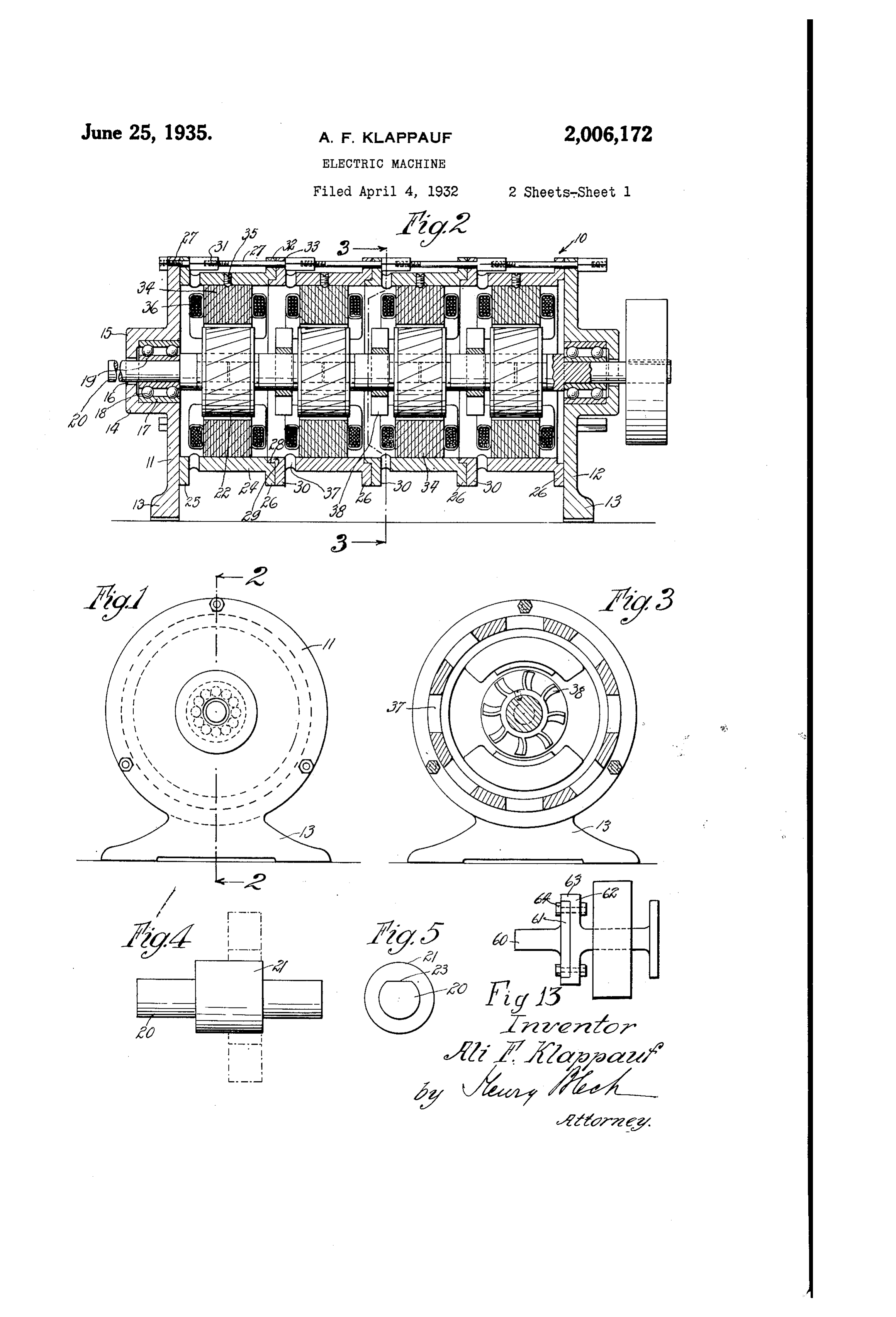
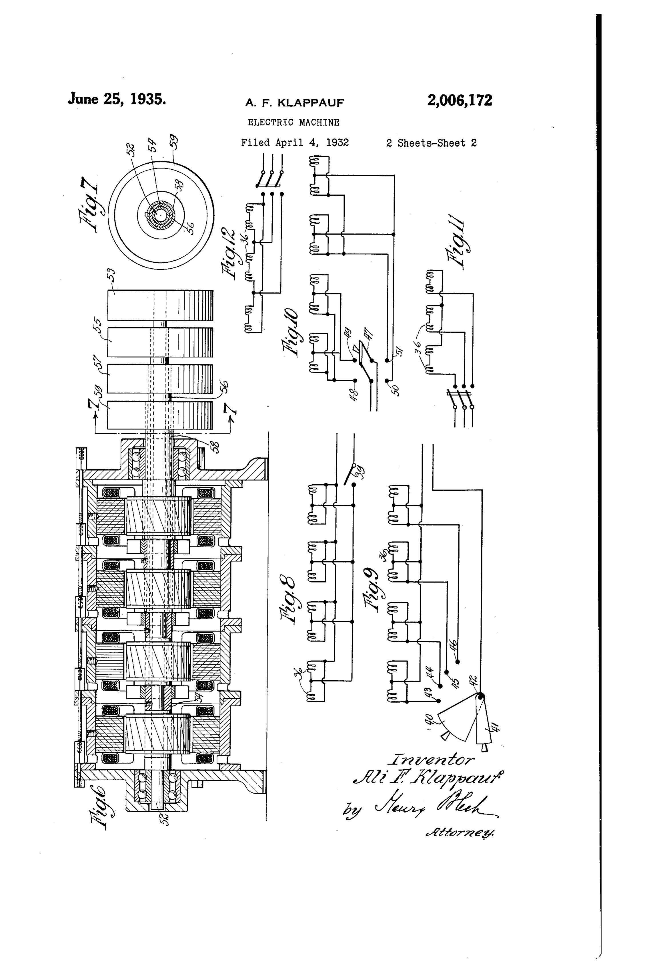
machine of the character specified wherein a With these and other equally important ob combination. Or multiple of fields or rotors are jects in view which will become apparent from assembled in Such relation to provide flexibility, a perusal of the invention, the latter comprises O Selectivity of power, Selectivity of speeds, direc the means described in the following specifica 0 tion of rotation, voltages and phases. tion, particularly pointed out in the claims form It is a further object of the invention to pro ing a part thereof, and illustrated in the accom vide a machine of the character Specified, where panying drawings, in which in a plurality of units each comprising a field and Fig. 1 is an end view of an electric machine 5 a rotorare assembled in compact relation to con constructed in accordance With my invention. 15 stitute a single machine and yet afford a great Fig. 2 is a section on the line 2-2 of Fig. 1. latitude of Selectivity of power, speed, direction Fig. 3 is a cross Sectional view, the Section of rotation, voltages and the like. being taken. On the line 3-3 of Fig. 2. It is a further object of the invention to pro Fig. 4 is a detailed view of a shaft provided vide a machine which comprises a plurality of with a spacing member which Serves as a Support 20 units which may be conveniently and rapidly for a fan.
mounted for operation and is economical in op Fig. 5 is an end view of the parts shown in eration. Fig. 4. .
It is a further object of the invention to pro Fig. 6 is a section similar to Fig. 2 of a modi 25 vide a machine of the character specified com fication. 25 posed of independent units, permitting operation Fig. 7 is a section. On the line - of Fig. 6. of Some of the units even though others become Figs. 8 to 12, inclusive, show diagrams of con disabled by short circuits, grounding, or other nections of the Various units in a circuit. disturbances or defaults. Fig. 13 is a detail View of a modified form of 30 A still further object of the invention consti shaft and associated parts for connecting another 30 tutes a provision of an electric machine in which shaft.
the horse power can be increased or decreased Referring to the several views in the draw Without the employment of electrical resistances ings, O generally indicates an electric machine in a rapid and convenient manner, either auto which is composed of a plurality of units each 35 matically or manually. comprising a rotor and a stator, said units being 35 It is also an object of the invention to provide assembled So that the machine operates as a sin a machine of the character specified in which gle machine. ?" Some of the units may rotate in one direction The electric machine comprises end plates while others rotate in the opposite direction at and f2 which are formed circularly, as shown 40 the same time. in Fig. 1, and formed integral With a base por 40 A Still further object aims at providing an elec tion 3 to support the machine. tric machine wherein a minimum starting cur It is, of course, Within the scope of the in rent is necessary to place the entire machine in vention to provide end plates of any other con
figuration, and the particular type of circular 45 Another object of the invention aims at provid construction is merely shown by way of example 45 ing an electric machine composed of a plurality and not by Way of limitation. of units, each comprising a rotor and a stator, wherein the rotor and the stator can be made in The end plates and 2 are provided with standard unit type sizes, so that the manufacture an integral hub f4 of hollow construction, which 50 of the units is simplified and delays in the re hub is open at the inner end and closed at the 50 placement of the units are avoided. Outer end by a wall 5 having a central aperture It is also an object of the invention to provide 6 for a purpose presently to be explained. an electric machine of the character specified The hub 4 has a bearing sleeve f T and spaced which may be used uninterruptedly even though therefrom by rollers 8, another bearing sleeve 55 one of the units becomes disabled by simply 9 is provided surrounding a shaft 20 whose free 35
Page 4
end protrudes through the hub opening 6 from speeds for each individual unit depending upon the hub. the field winding of the respective units, and said The Shaft 20 is provided with a spacing men units may be used singly or collectively. ber 2 seculed to the shaft intermediate its ends, In FigS. 8 to 12, inclusive, typical diagrams are 5 as shown in Fig. 4. shown in the manner in Which the machine is The shaft 20, in abutment with its spacing connected for various purposes. The diagrams member 2, carries a rotor 22 which may be of are merely illustrated by Way of giving a few ex any suitable or approved construction, and which amples but not for the purpose of disclosing all is adapted to execute a rotary motion under the the possible arrangements and changes that can O influence of the magnetic flux produced by the be made to explain the great latitude of Selec O magnetic fields of the machine when used as a tivity and flexibility possible with this machine. motor, as will be readily understood by those Thus in Fig. 8, the field coils 36 are connected versed in the art. in Single phase to a circuit, and this circuit is Attention is called to the fact that the end controlled by a switch 39, which operates a mu of the shaft 20 beyond the spacing member 2 tiple of units of power at 110 volts. 5 extends to a point short of the center of the In Fig. 9 a circuit is mentioned in which selec rotor and the other half of the rotor is Sup tivity is provided as to the number of units that ported by the adjacent end of the succeeding may be cut in or out in the operating circuit. As shaft. 20 of the second unit, as will be herein shown in Fig. 9, a switch 40 is provided which is 20 after further explained. Constructed as a Sector, and in Superposed rela Attention is called to the fact that the diam tion a Smaller switch 4 is provided, both being eter of the shaft is selected with a view of a C rotatable about a common pin 42. conmodating the maximum power available The switches co-operate with a series of con from the machine, and is preferably shaped to tact points 43, 44, 45 and 46, each contact point permit the securing of the rotor on the shaft being connected to each unit. It is, of course, to prevent relative rotation between these parts. within the scope of the invention to provide more As shown in Fig. 5, the shaft 20 is formed or less than four units, but four units have been with a flat face 23 So as to provide a key fit shown merely by way of a particular illustration. between the Shaft and the rotor. If the Switch 40 covers contact point 43 and 44, 30 The end plates and 2 are maintained in and in addition thereto the last unit connected 30 spaced relation by one or a plurality of drum to contact point 46 is Wanted, but the unit con Sections 24, as shown in Fig. 2, which are pro nected with contact point 45 is to be omitted, vided with circular end flanges 25 and 26. then in that case the Switch 40 is turned to cover The flange 25 is Secured to the end wall contact points 43 and 44 and in addition Switch 35 by a plurality of bolts 21. The end flange 26 is 4 is turned to cover contact point 46, so that in recessed as at 28 to provide a seat for a pro that case the first, Second, and last unit is cut jection 29 of the end flange 30 of the adjacent into the circuit While the third unit is eliminated. Section. Thus the end flanges 26 and 30 interfit It is obvious that any number of variations can to provide a continuous shield or housing for be provided by means of the employment of
the machine. Switches 40 and 4. Thus the first unit and the 40 The end flange 26 of the last unit shown in last two units may be cut in the circuit, or three Fig. 2 is secured to the end wall 2. consecutive unitS may be employed in accordance If the machine is to be constructed only as a With the particular requirements of the operator. single unit machine, then the end plate 2 is The provision of the tWO SWitches also enables maintained adjacent to the flange 26 of the first easy detection of whether or not one of the units unit shown at the left in Fig. 2 and is secured may be in Operative by reason of burning out or thereto by bolts Or any other approved, or con any other defect. If the Switch. 4 is placed in venient manner. contact with the various contact points 43 to The bolts 27 are provided with a hexagonal 46 Successively, the respective units are connect head 3, which is provided with a tapped bore ed for rotation of the unit and indicates that the 50 to receive in threaded relation the adjacent end units are in order. Whereas, non-rotation quick of the Succeeding bolt 2. ly establishes that One of the units is out of con The adjacent flanges 26 and 30 are provided mission, with coinciding apertures 32 and 33 to provide In Fig. 10, a diagram is shown in which two
for the passage of the bolts 27. units may be employed simultaneously, or the 55 In central relation to the drum Sections 24 is Other tWO units may be employed to provide for secured a detachable field core 34 held in place Ward or reverse rotation, or as emergency units. by a set Screw 35, and field coils 36 are wound If the Switch. 47, shown in Fig. 10, is placed in around the core capable of emitting a magnetic contact with points 48 and 49, then the first two fux Or establishing a magnetic field traversing units, shown in the diagram, rotate in one direc 60 60 the rotor, so as to set up inductions in the rotor tion. If, however, the Switch 47 is placed in con to produce electrical or mechanical power thereof. tact With points 50 and 5, then the remaining The field coils are, of course, dimensioned to tWo units Will rotate in the opposite direction be meet the various requirements of speed, power, Cause of the difference of the connections in the Voltages, and phases. tWO circuits. Of course, instead of providing the 65 Attention is called to the fact that each drum arrangement of for Ward and reverse rotation for section is provided with a plurality of openings the two units, the same applies to three units in 37 to provide for ingress and egress of air. One direction and a single unit in the opposite On the spacer member 21, a plurality of fan direction, or any further combination where more blades 38 are secured, so that upon rotation of than four units are being employed. 70 the rotor, air currents are set up for the cooling Fig. 11 shows the Operation of the machine for of the machine. Star connection, while in Fig. 12 the units are con The rotor 22 may be constructed of the squirrel nected in delta formation.
cage type or of the collector ring type. Attention is called to the fact that in employing The machine may be employed with separate the machine om a three phase system, either star 75
Page 5
Or delta, that even though one or more of the vantageous in holding the rotor in central rela units may rotate in one direction, while the re tion with respect to the field.
maining units may rotate in the Opposite direc While the drawings disclose a preferred embod tion at the same time. iment of the invention, the same are merely illus In order to eliminate the Surge of starting a trated by way of explanation and not by way of four unit type machine, one unit may be used at limitation. Numerous changes, alterations, and the start to bring the speed to Synchronism, and revisions may be made within the purview of the the other three units can then be cut in so that invention.
in this way of starting the machine, the starting I, therefore, do not wish to limit the invention 0 current is kept at a minimum. to the details of construction. Or arrangement of O Attention is called to the fact that by provid parts, as shown, but claim my invention as ing four units, selectivity of the horse power is broadly as the state of the art permits. possible by cutting in one or all of the units, either claim:
automatically or otherwise. 1. An induction motor including a sectional 15 Attention is called to the fact that the elec casing, a Sectional shaft, a motor unit including 5 tric machine not only can be employed as a motor, a field coil carried by each section of the casing but also as a generator, and a rotor for each field coil, each rotor serving The modification shown in Fig. 6 differs from to couple the meeting ends of the shaft sections the modification shown in Fig. 2 by the fact that against rotary movement with respect to each 20 instead of employing sectional shafts, telescop other and to the rotor, and means for connecting 20 ing shafts are employed which are extended to the sections of the casing together. have secured thereto pulleys from which power 2. An induction motor including a sectional may be taken off. casing, a sectional shaft, a motor unit for each Thus, the shaft 52 extends throughout the casing Section including a field coil carried by 25 machine, and there-beyond to carry at its free that Section and a rotor, each rotor fitting the 25 end a pulley 53. meeting ends of adjacent shaft sections and cou The tubular shaft 54 Surrounds the Solid Shaft pling Said Sections against independent rotary 52 and carries at its free end a pulley 55. movement without interfering with independent A hollow shaft 56 Surrounds the shaft 54 and axial movement, and means for connecting the 30 carries at its outer free end a pulley 57. casing Sections. 30 Likewise a hollow shaft 58 carries at its free . 3. An induction motor, including a sectional end a pulley 59. casing carrying a field coil, a sectional shaft made As far as the operation, selectivity and rear up of Sections having flattened peripheral por rangement are concerned with reference to the tions adjacent their meeting ends, a rotor for 35 first modification they apply with equal force to each field coil and arranged to embrace the meet 35 the Second modification. ing ends of the shaft sections, the rotor being The pulleys, 53, 55, 57 and 59, of course, will formed to interlock with the flattened ends of rotate in either direction depending on the con the shaft Sections to form a rotary couple, and nection of the respective unit. A greater selec means for Securing the sections of the casing 40 tivity can be obtained in rotation, speed and together. 40 power at the same time for the various units by 4. An induction motor including a sectional properly connecting the units in the circuit, as casing, a field coil carried by each section, a sec has been mentioned in connection with the first tional shaft made up of sections having their modification. meeting ends mutilated, a spacing element on 45 In Fig. 13 a different mode of connecting the each shaft section, a rotor for each coil formed 45 adjacent rotor shafts together is shown. The to cooperate with the meeting ends of adjacent shaft 60 of the rotor is provided at one end with shaft sections and interlocking with the mutilated a male flange 6, while the other end of the shaft portions of such shafts to provide a rotary couple is provided with a female flange 62 which is for adjacent shaft sections, the spacing element formed with a rim 63 of sufficient depth and diam On each shaft section maintaining the rotors in 50 eter to permit the male flange of the adjacent coupling relation to the shaft sections, and con Shaft to be received therein and secured to the necting means for the shaft sections to prevent female flange by a plurality of screws 64. This endwise movement for the sections, method of connecting the shafts together is ad A. F. KAPPAUF,
Provenance
- Collection
- Cited prior art
- Original PDF
- patentimages.storage.googleapis.com →
- Filed
- 1932-04-04
- Pages
- 5
- Method
- pdftotext (the PDF's own text layer) + pdftoppm 300dpi page scans
- Source
- Google Patents bibliographic record
- Granted
- 1935-06-25
- Inventors
- Ali F Klappauf
- Transcribed from
- patentimages.storage.googleapis.com →