patent · US3860843
Rotating electric machine with reduced cogging
14 January 1975
Page 1 — bibliographic record
United States Patent (19) [11] 3,860,843 Kawasaki et al. (45) Jan. 14, 1975 54) ROTATING ELECTRIC MACHINE WITH 56 References Cited REDUCED COGGING UNITED STATES PATENTS 75 Inventors: Itaru Kawasaki; Kazutsugu 3,230,434 lf 1966 Bauerlein........................ 3.0156 X Kobayashi; Yoshiaki Igarashi, all of 3,299,335 l/1967 Wessels........................... 31 Of 156 X Osaka, Japan 3,586,942 61971 McMahan....................... 310/156 X 73) Assignee: Matsushita Electric Industrial Co., Primary Examiner-Donovan F. Duggan Ltd., Osaka, Japan Attorney, Agent, or Firm-Wenderoth, Lind & Ponack
21 Appl. No.: 343,673 57 ABSTRACT Related U.S. Application Data A rotating electric machine of the multipole type which has a permanent magnet rotor magnetized in 63 Continuation of Ser. No. 154,450, June 18, 1971, such a way that the number of stator salient poles is abandoned.
less than the number of permanent magnet poles. The (30) Foreign Application Priority Data machine has a smaller cogging force and is easily man ufactured. The cogging force is made smaller by shap
June 26, 1970 Japan................................ 45-56347 ing both sides of the periphery of each stator salient June 26, 1970 Japan a aay --- -- - a ----- 45-56350 pole. The ratio of the number of the stator salient poles to the rotor permanent magnet poles is such as 52 U.S. Cl.................................... 310/67, 310/156 to make the rotation of the rotor smooth in spite of 5ll Int. Cl. ........................................... H02k 21/22 variations in the magnetization of the permanent mag 58 Field of Search............ 320/67, 156, 254-259, net rotor poles.
7 Claims, 3 Drawing Figures
Page 2
Drawing sheet — no readable text.
Page 3
Drawing sheet — no readable text.
Page 4
Drawing sheet — no readable text.
Page 5
ROTATING ELECTRIC MACHINE WITH the number of rotor permanent magnet poles, many REDUCED COGGNG stator coils are still required. In addition, the gaps be tween the stator salient poles must be large to permit
This application is a continuation of U.S. application forming the stator winding without difficulty. Further Ser. No. 154,450, filed June 18, 1971, now abandoned. more, the greater the number of poles in the rotating This invention relates to a new rotating electric ma electric machine, the narrower the top part of the sta chine, more particularly to a rotating electric machine tor salient pole which faces the rotor permanent mag the rotor of which has a multipole permanent magnet, net. As it is, the stator winding has an excessively short and the stator of which has a shape suitable for winding pitch compared with the pitch of the rotor magnet the stator coils quickly. 10 poles. Therefore, the magnetic flux of the rotor perma A multipole structure is indispensable for a rotating nent magnet is not fully utilized.
electric machine which rotates at a low speed, in spite The object of the invention is to provide a rotating of such a structure being hard to manufacture. Apart electric machine having a multipole rotor permanent from the difficulties in making a rotor permanent mag magnet which has a simple stator structure in order to net having a multipole structure, the stator for such a 15 make winding of the stator easy. machine and its winding are complicated. The conven Another object of the invention is to provide a rotat tional stator of multipole type consists of a plurality of ing electric machine having a smaller cogging force be teeth and slots. These slots become narrower as the tween the rotor permanent magnet and the stator core number of poles increases. Then it is difficult to wind made of magnetic material.
the stator winding directly and quickly around the 20 Other objects and advantages of the invention will teeth. These operations are difficult to mechanize. become apparent from the following detailed descrip In a lap winding the number of stator slots is a multi tion of an exemplary structure embodying the inven ple of the number of poles in the rotor permanent mag tion taken together with the accompanying drawings, in net. As all slots are occupied by stator coils, many sta which:
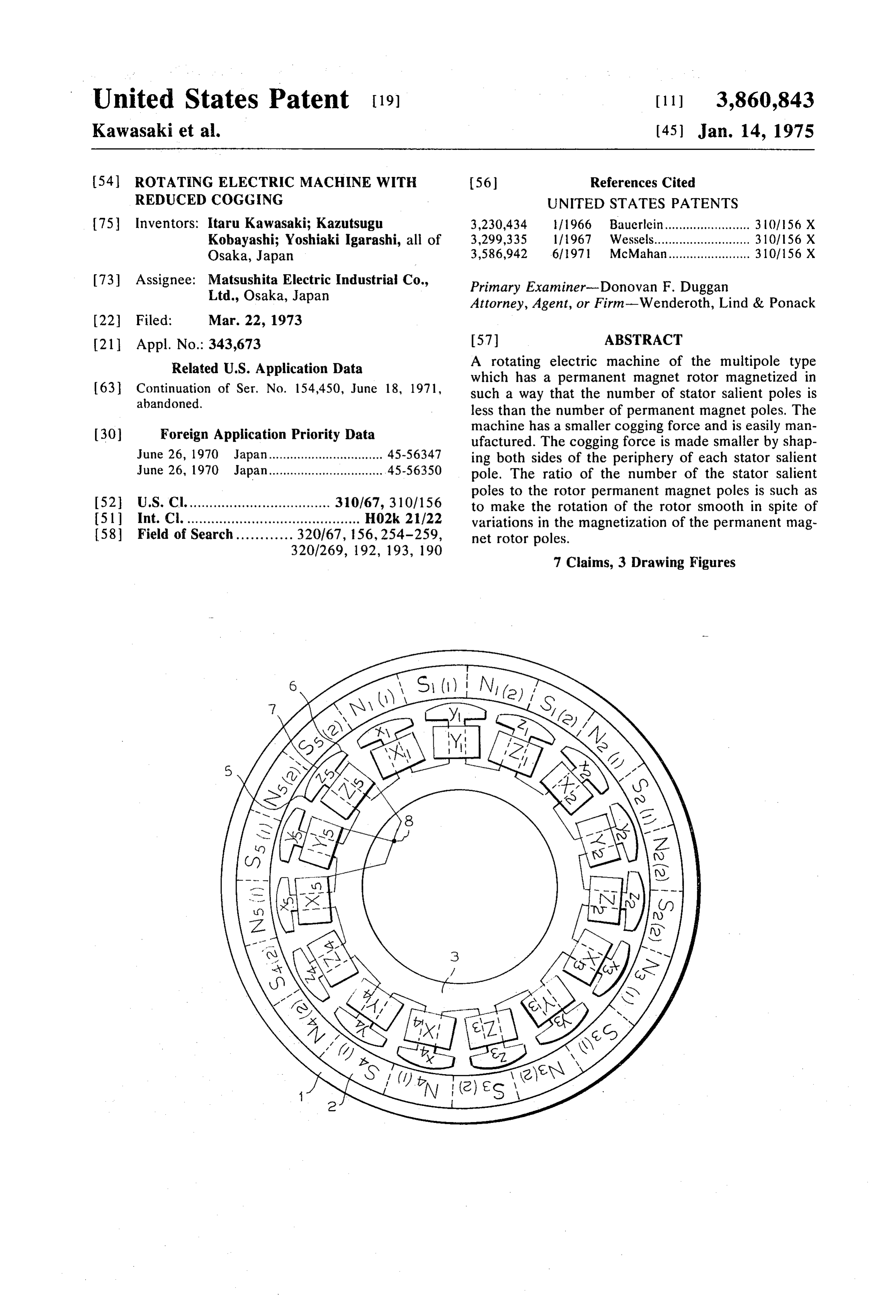
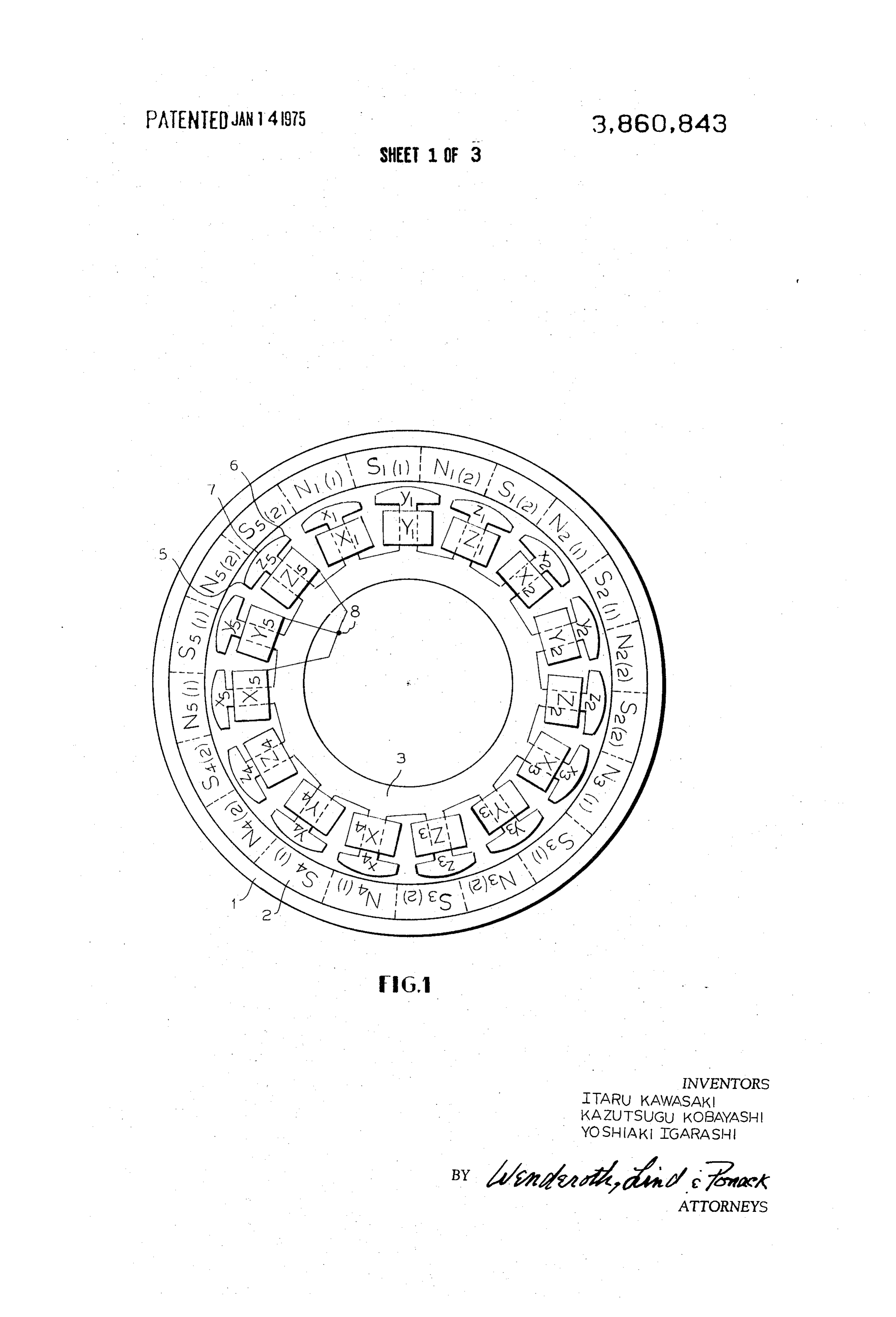
tor coils are required. After a plurality of coils are 25 FIG. 1 is a schematic view of a three-phase 20-pole formed beforehand, they are inserted into slots with a type D.C. motor having an arrangement of stator sa few slots between them, and they are connected to lient poles and rotor permanent magnet poles in accor each other so as to be able to interact with the rotor dance with one preferred embodiment of the present permanent magnet. As a results, the stator coils must invention;
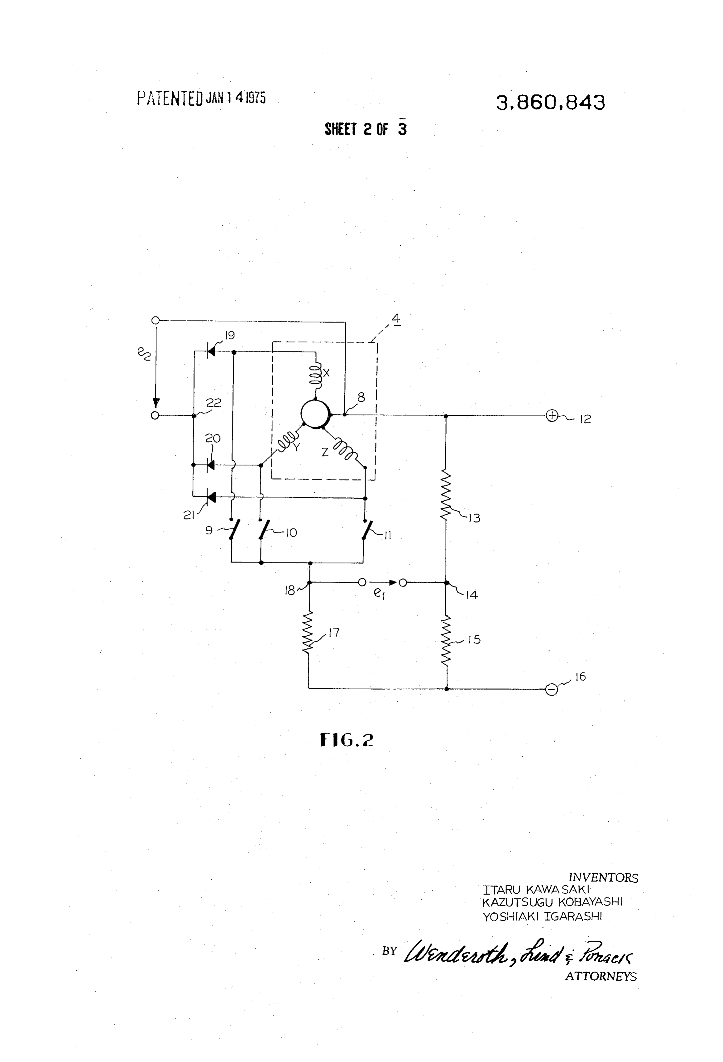
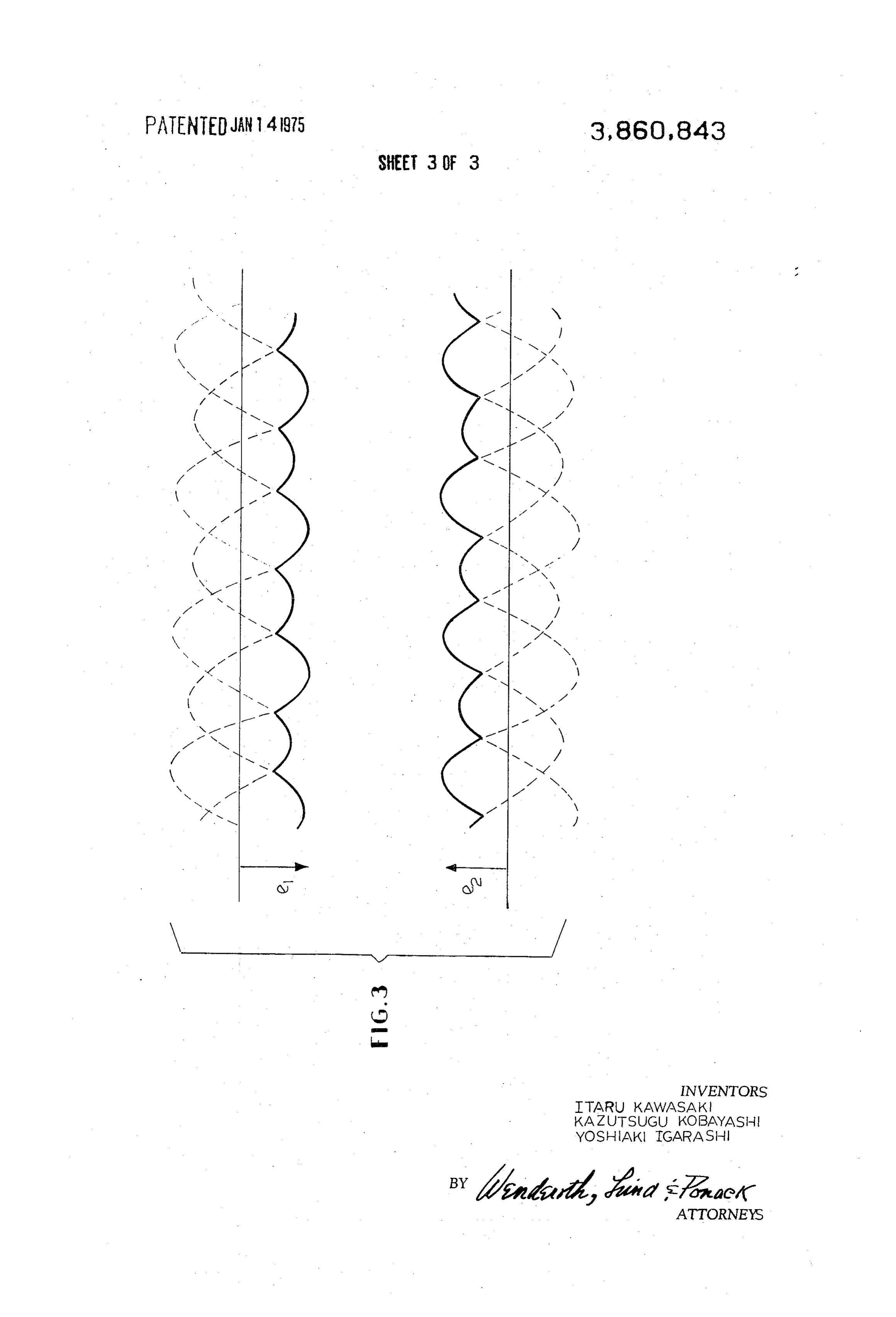
be loose in lap winding. The portions of the stator coil 30 FIG. 2 is a circuit diagram of a device for obtaining which occupy the slots contribute to generating a a control signal to regulate the speed of a rotating elec torque or an electromotive force. The other portions of tric machine for explaining the present invention; and the stator coil which do not occupy the slots, are inef FIG. 3 is a graph indicating the pattern of the control fective for generating torque or electromotive force. 35 signal obtained by the circuit of FIG. 2 when combined Said other portions of the stator coil are called "coil with the motor shown in FIG. 1.
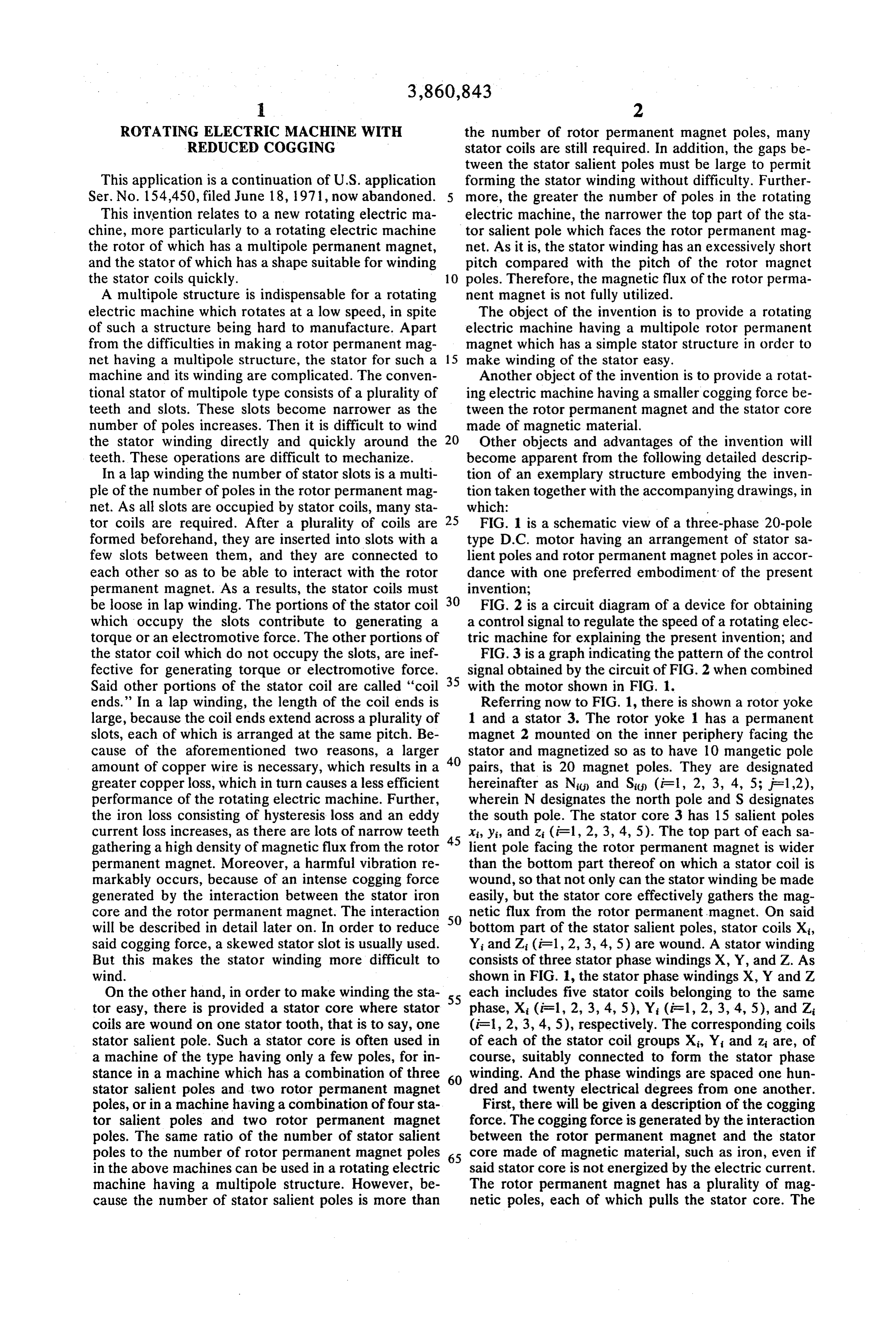
ends.” In a lap winding, the length of the coil ends is Referring now to FIG. 1, there is shown a rotor yoke large, because the coil ends extend across a plurality of 1 and a stator 3. The rotor yoke 1 has a permanent slots, each of which is arranged at the same pitch. Be magnet 2 mounted on the inner periphery facing the cause of the aforementioned two reasons, a larger 40 stator and magnetized so as to have 10 mangetic pole amount of copper wire is necessary, which results in a pairs, that is 20 magnet poles. They are designated greater copper loss, which in turn causes a less efficient hereinafter as Nic and S (i-1, 2, 3, 4, 5; F =1,2), performance of the rotating electric machine. Further, wherein N designates the north pole and S designates the iron loss consisting of hysteresis loss and an eddy the south pole. The stator core 3 has 15 salient poles current loss increases, as there are lots of narrow teeth x, yi, and z (iF1, 2, 3, 4, 5). The top part of each sa gathering a high density of magnetic flux from the rotor 45 lient pole facing the rotor permanent magnet is wider permanent magnet. Moreover, a harmful vibration re than the bottom part thereof on which a stator coil is markably occurs, because of an intense cogging force wound, so that not only can the stator winding be made generated by the interaction between the stator iron easily, but the stator core effectively gathers the mag core and the rotor permanent magnet. The interaction netic flux from the rotor permanent magnet. On said will be described in detail later on. In order to reduce 50 bottom part of the stator salient poles, stator coils X, said cogging force, a skewed stator slot is usually used. Yi and Z (iF1, 2, 3, 4, 5) are wound. A stator winding But this makes the stator winding more difficult to consists of three stator phase windings X, Y, and Z. As wind. shown in FIG. 1, the stator phase windings X, Y and Z On the other hand, in order to make winding the sta 55 each includes five stator coils belonging to the same tor easy, there is provided a stator core where stator phase, X (i-1, 2, 3, 4, 5), Y (i.e. 1, 2, 3, 4, 5), and Z coils are wound on one stator tooth, that is to say, one (i = 1, 2, 3, 4, 5), respectively. The corresponding coils stator salient pole. Such a stator core is often used in of each of the stator coil groups X, Y and z are, of a machine of the type having only a few poles, for in course, suitably connected to form the stator phase stance in a machine which has a combination of three 60 winding. And the phase windings are spaced one hun stator salient poles and two rotor permanent magnet dred and twenty electrical degrees from one another. poles, or in a machine having a combination of four sta First, there will be given a description of the cogging tor salient poles and two rotor permanent magnet force. The cogging force is generated by the interaction poles. The same ratio of the number of stator salient between the rotor permanent magnet and the stator poles to the number of rotor permanent magnet poles 65 core made of magnetic material, such as iron, even if in the above machines can be used in a rotating electric said stator core is not energized by the electric current. machine having a multipole structure. However, be The rotor permanent magnet has a plurality of mag cause the number of stator salient poles is more than netic poles, each of which pulls the stator core. The
Page 6
force between the stator and the rotor is influenced by quently, this rotating electric machine generates less the shape of the stator core and the distribution of the cogging force, and rotates smoothly. Because it is prac magnet charge in the rotor permanent magnet. Mathe tically free from wow and flutter, it is especially suit matically the cogging force is determined by the convo able for audio equipment.
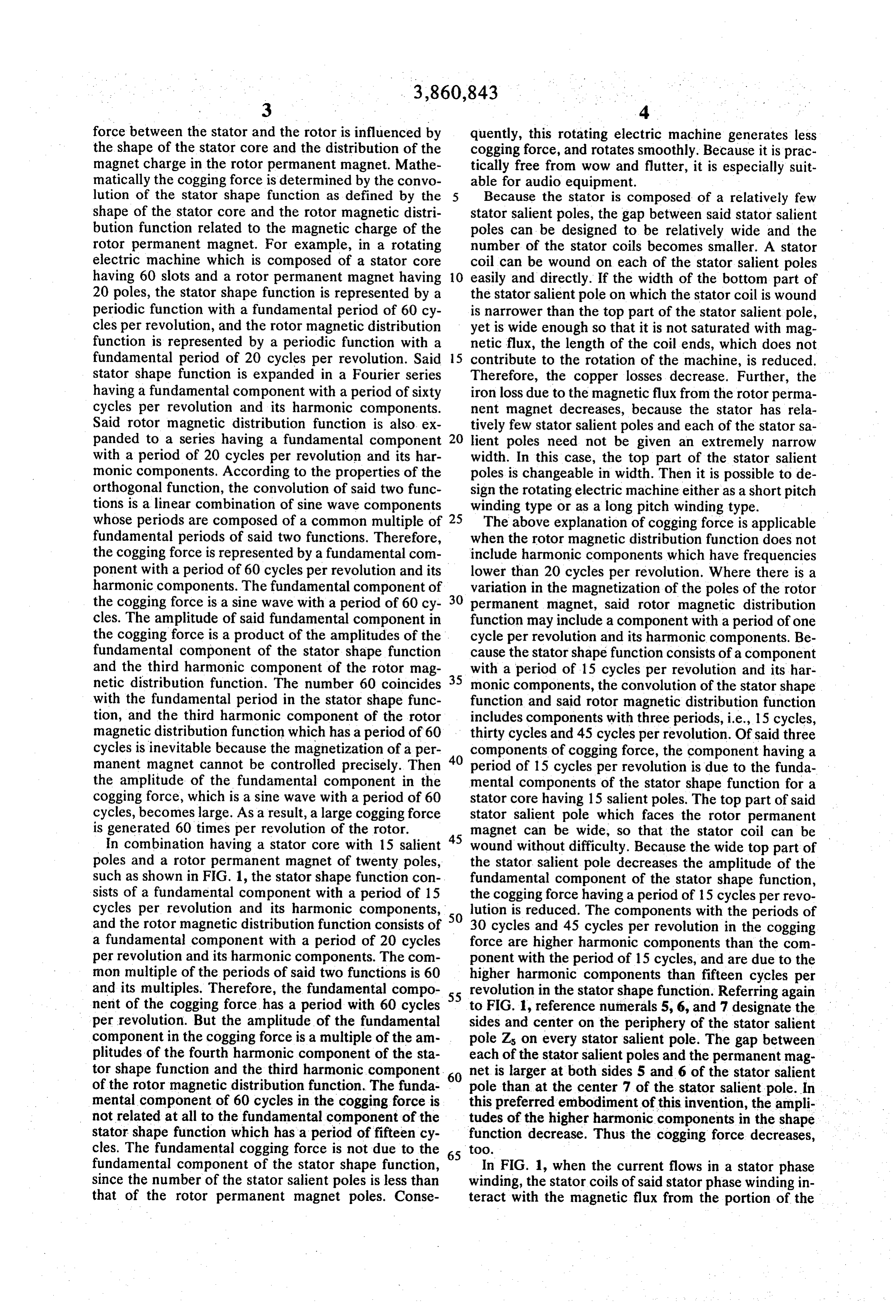
lution of the stator shape function as defined by the Because the stator is composed of a relatively few shape of the stator core and the rotor magnetic distri stator salient poles, the gap between said stator salient bution function related to the magnetic charge of the poles can be designed to be relatively wide and the rotor permanent magnet. For example, in a rotating number of the stator coils becomes smaller. A stator electric machine which is composed of a stator core coil can be wound on each of the stator salient poles having 60 slots and a rotor permanent magnet having 10 easily and directly. If the width of the bottom part of 20 poles, the stator shape function is represented by a the stator salient pole on which the stator coil is wound periodic function with a fundamental period of 60 cy is narrower than the top part of the stator salient pole, cles per revolution, and the rotor magnetic distribution yet is wide enough so that it is not saturated with mag function is represented by a periodic function with a netic flux, the length of the coil ends, which does not fundamental period of 20 cycles per revolution. Said 5 contribute to the rotation of the machine, is reduced. stator shape function is expanded in a Fourier series Therefore, the copper losses decrease. Further, the having a fundamental component with a period of sixty iron loss due to the magnetic flux from the rotor perma cycles per revolution and its harmonic components. nent magnet decreases, because the stator has rela Said rotor magnetic distribution function is also ex tively few stator salient poles and each of the stator sa panded to a series having a fundamental component 20 lient poles need not be given an extremely narrow with a period of 20 cycles per revolution and its har width. In this case, the top part of the stator salient monic components. According to the properties of the poles is changeable in width. Then it is possible to de orthogonal function, the convolution of said two func sign the rotating electric machine either as a short pitch tions is a linear combination of sine wave components winding type or as a long pitch winding type. whose periods are composed of a common multiple of 25 The above explanation of cogging force is applicable fundamental periods of said two functions. Therefore, when the rotor magnetic distribution function does not the cogging force is represented by a fundamental com include harmonic components which have frequencies ponent with a period of 60 cycles per revolution and its lower than 20 cycles per revolution. Where there is a harmonic components. The fundamental component of variation in the magnetization of the poles of the rotor the cogging force is a sine wave with a period of 60 cy 30 permanent magnet, said rotor magnetic distribution cles. The amplitude of said fundamental component in function may include a component with a period of one the cogging force is a product of the amplitudes of the . cycle per revolution and its harmonic components. Be fundamental component of the stator shape function cause the stator shape function consists of a component and the third harmonic component of the rotor mag with a period of 15 cycles per revolution and its har netic distribution function. The number 60 coincides 35 monic components, the convolution of the stator shape with the fundamental period in the stator shape func function and said rotor magnetic distribution function tion, and the third harmonic component of the rotor includes components with three periods, i.e., 15 cycles, magnetic distribution function which has a period of 60 thirty cycles and 45 cycles per revolution. Of said three cycles is inevitable because the magnetization of a per 40 components of cogging force, the component having a manent magnet cannot be controlled precisely. Then period of 15 cycles per revolution is due to the funda the amplitude of the fundamental component in the mental components of the stator shape function for a cogging force, which is a sine wave with a period of 60 stator core having 15 salient poles. The top part of said cycles, becomes large. As a result, a large cogging force stator salient pole which faces the rotor permanent is generated 60 times per revolution of the rotor. magnet can be wide, so that the stator coil can be In combination having a stator core with 15 salient 45 wound without difficulty. Because the wide top part of poles and a rotor permanent magnet of twenty poles, the stator salient pole decreases the amplitude of the such as shown in FIG. 1, the stator shape function con fundamental component of the stator shape function, sists of a fundamental component with a period of 15 the cogging force having a period of 15 cycles per revo cycles per revolution and its harmonic components, 50 lution is reduced. The components with the periods of and the rotor magnetic distribution function consists of 30 cycles and 45 cycles per revolution in the cogging a fundamental component with a period of 20 cycles force are higher harmonic components than the com per revolution and its harmonic components. The com ponent with the period of 15 cycles, and are due to the mon multiple of the periods of said two functions is 60 higher harmonic components than fifteen cycles per and its multiples. Therefore, the fundamental compo 55 revolution in the stator shape function. Referring again nent of the cogging force has a period with 60 cycles to FIG. 1, reference numerals 5, 6, and 7 designate the per revolution. But the amplitude of the fundamental sides and center on the periphery of the stator salient component in the cogging force is a multiple of the am pole Zs on every stator salient pole. The gap between plitudes of the fourth harmonic component of the sta each of the stator salient poles and the permanent mag tor shape function and the third harmonic component. 60 net is larger at both sides 5 and 6 of the stator salient of the rotor magnetic distribution function. The funda pole than at the center 7 of the stator salient pole. In mental component of 60 cycles in the cogging force is this preferred embodiment of this invention, the ampli not related at all to the fundamental component of the tudes of the higher harmonic components in the shape stator shape function which has a period of fifteen cy function decrease. Thus the cogging force decreases, cles. The fundamental cogging force is not due to the 65 tOO.
fundamental component of the stator shape function, In FIG. 1, when the current flows in a stator phase since the number of the stator salient poles is less than winding, the stator coils of said stator phase winding in that of the rotor permanent magnet poles. Conse teract with the magnetic flux from the portion of the
Page 7
rotor permanent magnet which faces said stator coils. The point 8 is connected to the power supplying termi The magnetic flux interlinking with the stator coils is nal 12.
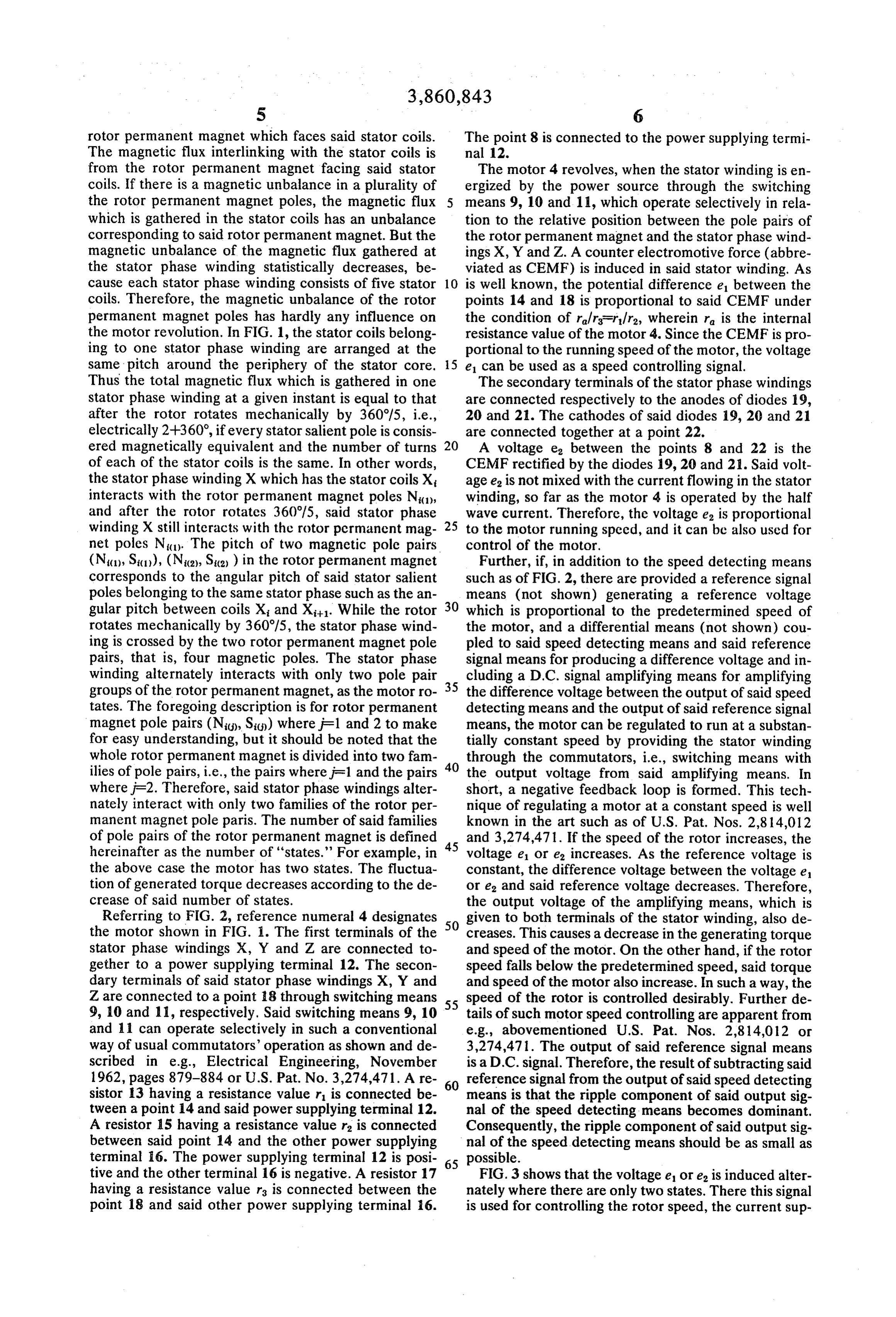
from the rotor permanent magnet facing said stator The motor 4 revolves, when the stator winding is en coils. If there is a magnetic unbalance in a plurality of ergized by the power source through the switching the rotor permanent magnet poles, the magnetic flux means 9, 10 and 11, which operate selectively in rela which is gathered in the stator coils has an unbalance tion to the relative position between the pole pairs of corresponding to said rotor permanent magnet. But the the rotor permanent magnet and the stator phase wind magnetic unbalance of the magnetic flux gathered at ings X, Y and Z. A counter electromotive force (abbre the stator phase winding statistically decreases, be viated as CEMF) is induced in said stator winding. As cause each stator phase winding consists of five stator 10 is well known, the potential difference e between the coils. Therefore, the magnetic unbalance of the rotor points 14 and 18 is proportional to said CEMF under permanent magnet poles has hardly any influence on the condition of r/r-r/r, wherein r is the internal the motor revolution. In FIG. 1, the stator coils belong resistance value of the motor 4. Since the CEMF is pro ing to one stator phase winding are arranged at the portional to the running speed of the motor, the voltage same pitch around the periphery of the stator core. 15 e can be used as a speed controlling signal. Thus the total magnetic flux which is gathered in one The secondary terminals of the stator phase windings stator phase winding at a given instant is equal to that are connected respectively to the anodes of diodes 19, after the rotor rotates mechanically by 360°/5, i.e., 20 and 21. The cathodes of said diodes 19, 20 and 21 electrically 2+360, if every stator salient pole is consis are connected together at a point 22. ered magnetically equivalent and the number of turns 20 A voltage ea between the points 8 and 22 is the of each of the stator coils is the same. In other words, CEMF rectified by the diodes 19, 20 and 21. Said volt the stator phase winding X which has the stator coils X age e is not mixed with the current flowing in the stator interacts with the rotor permanent magnet poles N1, winding, so far as the motor 4 is operated by the half and after the rotor rotates 360°/5, said stator phase wave current. Therefore, the voltage e is proportional winding X still interacts with the rotor pcrmanent mag 25 to the motor running speed, and it can bc also used for net poles N. The pitch of two magnetic pole pairs control of the motor.
(N(1), S(1), (N2), Sica) in the rotor permanent magnet Further, if, in addition to the speed detecting means corresponds to the angular pitch of said stator salient such as of FIG. 2, there are provided a reference signal poles belonging to the same stator phase such as the an means (not shown) generating a reference voltage gular pitch between coils X and X. While the rotor 30 which is proportional to the predetermined speed of rotates mechanically by 360/5, the stator phase wind the motor, and a differential means (not shown) cou ing is crossed by the two rotor permanent magnet pole pled to said speed detecting means and said reference pairs, that is, four magnetic poles. The stator phase signal means for producing a difference voltage and in winding alternately interacts with only two pole pair cluding a D.C. signal amplifying means for amplifying groups of the rotor permanent magnet, as the motor ro 35 the difference voltage between the output of said speed tates. The foregoing description is for rotor permanent detecting means and the output of said reference signal magnet pole pairs (Nig), Sid) where F1 and 2 to make means, the motor can be regulated to run at a substan for easy understanding, but it should be noted that the tially constant speed by providing the stator winding whole rotor permanent magnet is divided into two fam 40 through the commutators, i.e., switching means with ilies of pole pairs, i.e., the pairs where j=1 and the pairs the output voltage from said amplifying means. In where j=2. Therefore, said stator phase windings alter short, a negative feedback loop is formed. This tech nately interact with only two families of the rotor per nique of regulating a motor at a constant speed is well manent magnet pole paris. The number of said families known in the art such as of U.S. Pat. Nos. 2,814,012 of pole pairs of the rotor permanent magnet is defined 45 and 3,274,471. If the speed of the rotor increases, the hereinafter as the number of "states.' For example, in voltage e1 or e2 increases. As the reference voltage is the above case the motor has two states. The fluctua constant, the difference voltage between the voltage e tion of generated torque decreases according to the de or e, and said reference voltage decreases. Therefore, crease of said number of states. the output voltage of the amplifying means, which is Referring to FIG. 2, reference numeral 4 designates 50 given to both terminals of the stator winding, also de the motor shown in FIG. I. The first terminals of the creases. This causes a decrease in the generating torque stator phase windings X, Y and Z are connected to and speed of the motor. On the other hand, if the rotor gether to a power supplying terminal 12. The secon speed falls below the predetermined speed, said torque dary terminals of said stator phase windings X, Y and and speed of the motor also increase. In such a way, the Z are connected to a point 18 through switching means 55 speed of the rotor is controlled desirably. Further de 9, 10 and 11, respectively. Said switching means 9, 10 tails of such motor speed controlling are apparent from and 11 can operate selectively in such a conventional e.g., abovementioned U.S. Pat. Nos. 2,814,012 or way of usual commutators' operation as shown and de 3,274,471. The output of said reference signal means scribed in e.g., Electrical Engineering, November is a D.C. signal. Therefore, the result of subtracting said 1962, pages 879-884 or U.S. Pat. No. 3,274,471. A re reference signal from the output of said speed detecting sistor 13 having a resistance value r is connected be 60 means is that the ripple component of said output sig tween a point 14 and said power supplying terminal 12. nal of the speed detecting means becomes dominant. A resistor 15 having a resistance value r is connected Consequently, the ripple component of said output sig between said point 14 and the other power supplying nal of the speed detecting means should be as small as terminal 16. The power supplying terminal 12 is posi 65 possible.
tive and the other terminal 16 is negative. A resistor 17 FIG.3 shows that the voltage e ore is induced alter having a resistance value r is connected between the nately where there are only two states. There this signal point 18 and said other power supplying terminal 6. is used for controlling the rotor speed, the current sup
Page 8
plied to the stator winding depends on the signale or positioned at the same position as that of the corre e. The rotor can rotate most smoothly when the num sponding pole of said rotor.
ber of the states is a minimum. 2. A rotating electric machine as defined in claim 1, The group of the adjacent stator salient poles which wherein said stator winding has 3 phases, and said per includes only one stator coil of the respective stator manent magnet has a number of poles in a ratio of 4/3 winding phase is designated as "a stator element' here to the number of said salient poles. inafter. For the motor shown in FIG. 1, a stator element 3. A rotating electric machine as defined in claim 2, consists of three stator salient poles, and faces two pole wherein each of said salient poles faces said permanent pairs of the rotor permanent magnet. magnet and has the pole face shaped such that the gap If “a stator element' faces p pole pairs of the rotor 10 between each salient pole and said permanent magnet permanent magnet, the magnetic flux interacting with is larger at the sides of said salient pole than at the cen each stator winding has p states. As the number of the ter thereof so that the cogging force decreases for har states relates to the wow-flutter characteristic, it is de monic components higher than a number of cycles per sirable that the number of said states should be a mini revolution of the rotor equal to the number of salient mum. In a five phase rotating electric machine, the sta 15 poles.
tor element consists of five stator salient poles. Said sta 4. A rotating electric machine as defined in claim 1, tor element must face two pole pairs, i.e., four poles, of wherein each of said salient poles faces said permanent the rotor permanent magnet in order to have two magnet and has the pole face shaped such that the gap states. But this combination is not possible, because the between each salient pole and said permanent magnet number of stator salient poles would be greater than 20 is larger at the sides of said salient pole than at the cen the number of the rotor permanent poles. Therefore, ter thereof so that the cogging force decreases for har the stator element would face three pole pairs, i.e., six monic components higher than a number of cycles per poles, of the rotor permanent magnet and this motor revolution of the rotor equal to the number of salient will have three states. Generally, if the stator winding poles.
has (2n+1) phases where n is an integer, it is most ade 25 5. A rotating electric machine comprising a rotor quate where the number of the stator salient poles is having a permanent magnet with a plurality of poles less than the number of the rotor permanent poles and therearound, a stator core having a plurality of salient the permanent magnet has poles in a ratio of poles therearound, and a plurality of stator coils, each (2n+2)/(2n+1) to the number of said salient poles and of which is wound on each of said salient poles and the number of states is (n+1). If the stator winding has 30 which are connected to each other so as to form a sta (2n) phases, it is most adequate that the permanent tor winding having a plurality of phases, wherein said magnet has a number of poles in a ratio of (n+1)/n to stator winding has 2n phases, and said permanent mag the number of said salient poles and the number of net has a number of poles in a ratio of (n+1)/n to the states is (n+1). The rotating electric machine which number of said salient poles, and each of said stator sa has only two states must have rotor permanent poles 35 lient poles belonging to one phase being magnetically and stator salient poles for a ratio of 4/3 in three phase positioned at the same position as that of the corre winding or 4/2 for a two phase winding. But the latter sponding pole of said rotor.
machine cannot start by itself, when it is used as the 6. A rotating electric machine comprising a rotor D.C. motor, because the number of the rotor perma having a permanent magnet with a plurality of poles nent magnet poles is a multiple of the number of the 40 therearound, a stator core having a plurality of salient stator salient poles. Thus the former machine is supe poles therearound, and a plurality of stator coils, each rior to the others. Expecially when an electronic com of which is wound on each of said salient poles and mutator is used, a machine with fewer phases, such as which are connected to each other so as to form a sta three phases, is desirable in order to reduce the number tor winding having a plurality of phases, the number of of electronic parts of the driving circuits. 45 said salient poles being a multiple of the number of Various modifications may be made to the examples phases and less than the number of said permanent described. Thus, for instance, if the stator winding is magnet poles, wherein each of said salient poles faces energized by A.C. current instead of D.C. current, said said permanent magnet and has the pole face shaped rotating electric machine can be operated as a multi such that the gap between each salient pole and said pole type synchronous motor which runs at low syn 50 permanent magnet is larger at the sides of said pole chronous speed, and which has many advantages as de than at the center thereof, so that the cogging force de scribed hereinbefore. creases for harmonic components higher than a num What we claim is: : ber of cycles per revolution of the rotor equal to the 1. A rotating electric machine comprising a rotor number of salient poles.
having a permanent magnet with a plurality of poles 55 7. A rotating electric machine as defined in claim 5, therearound, a stator core having a plurality of salient wherein each of said salient poles faces said permanent poles therearound, and a plurality of stator coils, each magnet and has the pole face shaped such that the gap of which is wound on each of said salient poles and con between each salient pole and said permanent magnet nected to each other so as to form a stator winding hav is larger at the sides of said salient pole than at the cen ing a plurality of phases, wherein said stator winding 60 ter thereof so that the cogging force decreases for har has (2n+1) phases, and said permanent magnet having monic components higher than a number of cycles per a number of poles in a ratio of (2n +2)/(2n+1) to the revolution of the rotor equal to the number of salient number of said salient poles, and each of said stator sa poles.
lient poles belonging to one phase being magnetically sk xk is k sk
Provenance
- Collection
- Cited prior art
- Original PDF
- patentimages.storage.googleapis.com →
- Filed
- 1973-03-22
- Pages
- 8
- Method
- pdftotext (the PDF's own text layer) + pdftoppm 300dpi page scans
- Source
- Google Patents bibliographic record
- Granted
- 1975-01-14
- Inventors
- Itaru Kawasaki; Kazutsugu Kobayashi; Yoshiaki Igarashi; Matsushita Electric Industrial Co Ltd
- Transcribed from
- patentimages.storage.googleapis.com →