patent · US6037692
High power low RPM D.C. motor
14 March 2000
Page 1 — bibliographic record
United States Patent (19) 11 Patent Number: 6,037,692 Miekka et al. (45) Date of Patent: Mar. 14, 2000 54 HIGH POWER LOW RPM D.C. MOTOR 5,123,079 6/1992 Tanii et al. .............................. 388/827 5,125,067 6/1992 Erdman ................................... 388/811 76 Inventors: Fred N. Miekka, 234 San Gabriel Ct.; 5,179,307 1/1993 Porter ............. ... 310/68 B Peter W. Mackie, 276 Grandview Ave., 5,696,419 12/1997 Rakestraw et al. ..................... 310/268 both of Sierra Madre, Calif. 91024 Primary Examiner Nestor Ramirez
Assistant Examiner Joseph Waks 21 Appl. No.: 09/088,096 Attorney, Agent, or Firm-Eric K. Satermo 22 Filed: Jun. 1, 1998 57 ABSTRACT Related U.S. Application Data A high power low RPM direct current electric motor is disclosed whereby the high power output is achieved in one 63 Continuation-in-part of application No. 08/991,926, Dec. of two ways or both. In the first case, the need for cooling 16, 1997. is reduced simultaneously along with an increase in the (51) Int. Cl." ....................................................... H02K 1/00 utilization of the magnetic field present in the motor per 52 U.S. Cl. ........................ 310,198.s 31.06s R.s 310/181
manent magnets. This is achieved by Wrapping the electro magnet core with windings that are capable of demagnetiz 58 Field of Search .................................. 310,198.67R, ing the rotormotor
Interlocking permanent circuitrymagnets understall is provided conditions.
which prevents the 310/68 R, 154, 156, 268, 181; 388/924, full activation of these motor windings until motor RPM 925, 800; 318/439 values reach a safe level. This increases motor power while 56) References Cited decreasing resistive losses in electromagnet windings. In the Second case, the rotary portion consists of a large diameter
3,686,524 8/1972 Hall .........................................
is ing built in vanes for moying air over the electromagnet
Stator windings providing forced air cooling.
4,015,181 3/1977 Karube et al. .......................... 388/816 4,710,667 12/1987 Whiteley ................................. 310/268 11 Claims, 21 Drawing Sheets
Page 2
Drawing sheet — no readable text.
Page 3
Drawing sheet — no readable text.
Page 4
Drawing sheet — no readable text.
Page 5
Drawing sheet — no readable text.
Page 6
Drawing sheet — no readable text.
Page 7
Drawing sheet — no readable text.
Page 8
Drawing sheet — no readable text.
Page 9
Drawing sheet — no readable text.
Page 10
Drawing sheet — no readable text.
Page 11
Drawing sheet — no readable text.
Page 12
Drawing sheet — no readable text.
Page 13
Drawing sheet — no readable text.
Page 14
Drawing sheet — no readable text.
Page 15
Drawing sheet — no readable text.
Page 16
Drawing sheet — no readable text.
Page 17
Drawing sheet — no readable text.
Page 18
Drawing sheet — no readable text.
Page 19
Drawing sheet — no readable text.
Page 20
Drawing sheet — no readable text.
Page 21
Drawing sheet — no readable text.
Page 22
Drawing sheet — no readable text.
Page 23
HIGH POWER LOW RPM D.C. MOTOR inward, and the other Set of poles against the Steel casing to magnetically connect them in Series. The motor casing with
CROSS-REFERENCE TO RELATED its electromagnets made up the Stator portion of the motor. APPLICATIONS When power was on, these electromagnets maintained the This is a continuation-in-part application of U.S. patent Same field. At each end of the motor casing were end caps having holes which were centrally located which Supported application Ser. No. 08/991,926 filed Dec. 16, 1997. a bushing or bearing through which the rotational portion (or BACKGROUND OF THE INVENTION rotor) was Supported. The rotor consisted of a round shaft having a larger diameter Set of electromagnet windings 1. Field of the Invention wound onto an iron core. The ends of the rotor windings The present invention relates to electric motorS and, more were fixed to conductive copper Strips that were insulated particularly, to direct current electric motorS Suitable for from each other and the motor casing using resin or other reliably and efficiently powering electric Vehicles and indus Suitable insulating material. A set of brushes which were trial machinery. usually made of graphite pushed up against the copper Strips 2. Description of Related Art 15 in the rotor to make electrical contact while also allowing the rotor to rotate. The position of the brushes relative to the
There are numerous electric motors available for propel Stator electromagnet windings was always Set So that the ling electric automobiles. These include both direct current proper rotor electromagnets were turned on at the appropri (DC) motors designed to drive directly off of the batteries ate times by the brushes to always magnetically drive the and alternating current (AC) motors which require electrical circuitry for converting the DC power in the batteries to AC rotor in the same direction (i.e., by interaction of the Stator magnetic field with the magnetic field of the electromagnets power. The most efficient of these AC motors requires three in the rotor).
or more phase power. While these motors were suitable for powering both Such motors have a high power-to-weight ratio, can be electric cars, as well as industrial equipment. Their effi made to run efficiently, and are inherently reliable because of 25 ciency was Somewhat limited by the fact that power losses their brushless design. A disadvantage of Such motorS is the occurred in both Sets of electromagnets due to the resistance fact that the battery power must be first converted to AC of their windings.
before it can be used by the motor. This disadvantage shows In the early 1930s, the General Electric Company devel up in the need for complex circuitry. This is especially true oped the first permanent magnets that were strong enough to for AC motors having three or more phases. Along with the replace one set of electromagnet windings in DC motorS. need for complex circuitry is the fact that the failure of even This Permanent magnet material was called Alnico, and a single electrical component in the System can result in total Soon Several grades were made commercially available. failure of the drive circuitry for producing AC power. This Shortly thereafter, the first useful permanent magnet motors results in DC electric power in the batteries, and a motor that began to appear. These motors basically used permanent requires AC power. This renders the entire drive System 35 magnets to replace the Stator electromagnets. While these useleSS.
motorS had an increased efficiency when compared to their
Therefore, such drive systems suffer from the potential of predecessors, they Suffered from the possibility of demag leaving the driver Stranded. Despite these obstacles, com netization of the permanent magnets if the electromagnetic panies Such as AC Propulsion Inc. have made considerable field in the rotor exceeded the “coercive force” (a measure advances in the use of AC motors in electric cars. In 40 of the resistance to demagnetization of permanent magnets) particular, high power to weight ratioS have been achieved. of the permanent magnets in the Stator. To partially alleviate In the powering of industrial machinery, in many appli this problem, Stronger ceramic permanent magnets were cations it is desirable to have an electric motor that has developed, and Still Stronger magnets called “Rare Earth considerable amounts of torque and power at relatively low Magnets' are among the most recent developments. RPM values. This is normally achieved by gearing the motor 45 All DC permanent magnet motors run the risk of demag down, however this practice results in added moving parts, netization of their permanent magnets if the electromagnetic increased mechanical losses, and adds cost and complexity field of the windings exceed the coercive force of the to the overall System. In general DC electric motors have permanent magnets. To alleviate this problem, a maximum good torque characteristics which make them ideal for use in Safe operating Voltage for any DC permanent magnet motor many industrial applications. In general with DC electric 50 is specified which under maximum power conditions (i.e., at motors, the more mechanical drag on the motor, the more Stall) the resistance of the electromagnet windings will be torque is produced. In this respect Such motors are ideal for high enough to prevent a flow of current through the propelling electric cars as well. This is especially true if one electromagnet Sufficient to cause irreversible damage to the wants to drive the wheels of such a vehicle directly by permanent magnets. This current is considerably greater employing a motor in the wheel hub. There are Several 55 than the normal operating current, and for this reason, reasons why DC electric motors are advantageous. normal operating conditions for traditional permanent mag DC electric motors require little circuitry to drive them net DC electric motors only utilize a fraction of their true from batteries. In some cases they can be wired directly with power capabilities based on their permanent magnets. In only a Switch to turn the System on and off. Another fact, most of these motors only utilize between 10% and advantage offered by DC electric motors is the fact that such 60 25% of their true potential.
motorS do not require Starting circuitry in the way that many The wire diameter used in winding an electromagnet core AC motors do. basically determines the magnetization force in ampere The first electric cars were produced at the turn of the turns for a given cross-sectional core diameter at a given century and were powered by DC electric motors. Such Voltage. Increasing the number of turns reduces the number motorS utilized two Sets of electromagnets to produce their 65 of amperes that will flow through the coil, but increases the torque. One Set was mounted to the inside of the motor number of turns thus, maintaining the same number of casing. These electromagnets had one set of poles facing ampere-turns. In order to more effectively use the permanent
Page 24
magnets of a permanent magnet motor under normal running destroy the Stator permanent magnets. With an armature conditions (i.e. at 10% to 25% of stall current) electromag resistance of 2.4 ohms (measured at Stall) this gives a net windings must be activated that are more than capable of maximum Safe operating Voltage of 48 volts without the risk demagnetizing the permanent magnets in the motor under of damaging the Stator permanent magnets. Of course other the conditions of stall. One way to accomplish this is to wind factors need to be considered before exceeding the manu the electromagnet in layers and using thinner wire Succes facturerS Specifications, but this electric motor can handle Sively in the outer layers. On Start up, all the layers of wire Stall at 48 volts before demagnetizing the Stator permanent in the electromagnet are used. The resistance of the thinner magnets. This gives a power rating considerably higher than outer wire prevents excessive currents in the motor thus the original manufacturerS Specifications. If one wants to run preventing demagnetization of the motor permanent mag this particular motor at 48 volts and at 25% of stall torque nets. Once the motor RPM value reaches a safe level, the (Maximum mechanical work output before excessive volt outer layers are shunted, thus increasing ampere turns in the age drops across the windings occur) at 48 volts, and about motor and increasing the utilization of the motor permanent 5 amperes, 240 watts of power will be delivered to the motor magnets. An interlock is also provided that prevents acci at 1,500 RPM with an approximate efficiency of 75%, dental activation of the shunt mechanism under Stall or low 15 producing 180 watts of mechanical work and 60 watts of RPM conditions. Other methods may be employed to wind waste heat being generated in the motor windings. In this electromagnet cores providing this type of electromagnet. case the permanent magnet utilization during running is 25% Also included is twisting two or more Strands of a given of their true capability. If one wants to increase the torque thickness insulated electromagnet wire together and winding output at this RPM value, it is necessary to further utilize the the core. At one end the two Strands are connected. This Stator permanent magnets during running. This can be becomes the common. At the other end, the two leads are accomplished using motor windings in the armature that are kept Separate. On motor Start up, only one lead is connected. more than capable of demagnetizing the Stator permanent Once motor RPM values reach a safe level, the second lead magnets under Stall conditions, and not fully activating these is connected to the first thereby increasing the utilization of windings until the motor RPM reaches a safe value that will the permanent magnets by providing more ampere-turns in 25 not demagnetize the Stator permanent magnets. The follow the motor electromagnet assembly. ing theoretical analysis will illustrate this point. This increased utilization of permanent magnets during An arbitrary number of 100 turns is chosen for the wire running conditions results in an electric motor having excep that wraps the electromagnet core. This gives a value of tionally high torque values. The example outlined below will 2,000 ampere-turns before demagnetization occurs. A wire be used to further illustrate this point. diameter is chosen to wrap the electromagnet rotor core that Ametek Corporation is a major manufacturer of electric is half the resistance of the original wire. If the same number motors. They manufacture a DC permanent magnet motor of turns are used,(100) an armature resistance of 1.2 ohms which is nominally rated at 24 volts. #116281-00. It is would be the result. Since the same number of turns is used, reversible and has a no load speed of 980 RPM. Measure if 48 volts is applied to the armature windings under Stall ment of the armature resistance under Stall conditions gives 35 conditions, 4,000 ampere-turns would result. Twice the 2.4 ohms. According to the manufacturerS Specifications, it magnetic field needed to demagnetize the Stator permanent is desirable to run this motor at 750 RPM. This value magnets (assuming that core Saturation effects are represents about 25% of stall torque at 24 volts input. Under negligible). Now this particular motor as is would not be these conditions, 2.75 amperes of current flow through the suitable for running at 48 volts because if even 50% of stall motor windings. The Voltage drop is equal to the Resistance 40 torque is achieved, the Stator permanent magnets will be at in ohms times the current in amperes. This is equal to 2.4 least partially demagnetized. A Second Set of electromagnet ohmsx2.75 amperes=6.6 volts. This leaves 17.4 volts for windings is employed in Series with the first Set of windings contributing to mechanical work giving the motor an effi using wire of three times the electrical resistance as the first ciency of about 73%. The mechanical output when using this original Set. This Set of windings is then wound with the motor under the manufacturers recommended Voltage, 45 same number of turns (100) as the first set giving a resistance torque, and RPM values is 2.75 amperesx24 voltsx0.73 of 3.6 ohms. The total resistance of the two windings efficiency factor to give 48 watts or about 0.063 horsepower. combined is 4.8 ohms. Since the electromagnet core has Running under the conditions of less torque increases motor twice the number of original turns,(200) in terms of demag efficiency however is detrimental to power output. Loading netization (2000 ampere-turns) this motor would have a safe down the motor to increase torque has the effect of trading 50 operating current of 10 amperes. With an armature resistance torque for RPM which results in virtually no increase in of 4.8 ohms, a maximum operating Voltage of 48 volts can mechanical work output accompanied by a rapid increase in be employed under the conditions of Stall without demag power losses in the motor windings. netizing the Stator permanent magnets. Accordingly, The manufacturer also provided the maxi Now assume that at Start up, this particular motor is mum current before demagnetization occurs in the motor. 55 connected to a 48 volt power Source. At Start up, all of the This occurs at a current of 20 amperes through the windings. windings are activated causing a current of 10 amperes to Note the fact that up to 20 amperes can be delivered to the flow. 2,000 ampere-turns results in the electromagnet which motor before damaging the permanent magnets, but the is just shy of the magnetic field needed to demagnetize the manufacturer also specifies the best load value to run the Stator permanent magnets. The rotor under this strong mag motor at is 2.75 amperes. Therefore during normal running 60 netic field Starts to Spin rapidly, and the current along with conditions, only 13.7% of the capability of the permanent its associated magnetic field Starts to weaken. At Some RPM magnets are utilized. This indicates that under the proper value, it is now Safe to shunt out the outer high resistance conditions that this motor can put out 7.3 times this torque turns of wire thus activating only the lower resistance inner value at this RPM value before demagnetizing the stator turns. Since 25% of stall current is the desired operating permanent magnets. 65 range, and the rotor electromagnets have the Same number AS is, this motor can withstand 20 amperes through its of turns as the original motor, at 1,500 RPM the motor electromagnet windings before demagnetization effects efficiency is 75%, but the torque is twice the value as the
Page 25
S 6 original motor, and the permanent magnets are being utilized electromagnets in the Stator as is done with brushleSS at 50% instead of 25%. This motor is now putting out twice designs but use a brush System for timing. The timing Signal the power as it was originally. 480 watts of input power is is then amplified electronically using transistors. This elimi providing 360 watts of mechanical work accompanied by nates many of the problems in brush timed motors by 120 watts of waste heat. This method of increasing the Significantly reducing the power that flows through the brush power output of permanent magnet motorS is quite effective. commutator system. This allows the brushes to be made This process however needs to be made user friendly. This from Such materials as conductive kapton polyimide film, requires that the end user of Such motorS does not have to and also for the use of commutators made from copper clad think about damaging Such motors by fully activating the circuit board material. With this type of hybrid brush timing lower resistance motor windings. In order to accomplish this System, keeping the inverted design features normally found end, interlocking circuitry is needed in order to prevent the in brushleSS motorS is beneficial when employing multiple accidental demagnetization of permanent magnets in these winding electromagnets.
permanent magnet motorS. BrushleSS permanent magnet motors are ideal for increas Another example of how this approach can yield positive ing permanent magnet utilization during running by employ results would be to employ the thick inner windings of the 15 ing the teachings of this invention. With the electromagnets previous example with its thinner associated outer windings, in the Stator instead of the rotor, the use of multiple elec but only run the motor at 12.5% of stall instead of 25% of tromagnet windings is easily achieved. In addition Since the stall. In this way, this electric motor would utilize the Switching of the electromagnets is now achieved using permanent magnets by only 25%, the same utilization as the electrical Switching circuitry, interlocking of the individual original motor without these modified windings. The motor electromagnet windings becomes a relatively easy task to efficiency, however would be significantly improved from perform. Speed Sensing is critical as it is now used as a about 75% to 88%. As now the thicker electromagnet determining factor in the interlocking of various electro windings would have leSS resistive losses. Of course the magnet winding configurations. This serves the all important Same precautions to guard against demagnetizing the per function of protecting the permanent magnets from acciden manent magnets would have to be taken. 25 tal demagnetization. Several Speed Sensing and interlocking In these particular cases, the connections to the electro approaches may be used. For example, for relatively large magnet windings are difficult to achieve because the elec motors, a Small electric generator may be placed onto the tromagnet is embedded into the rotary part of the motor. Not power output shaft of the motor and wired to a relay which that this cannot be achieved, it can, in at least two different closes the appropriate contacts at a predetermined generator ways. output voltage. This System is a good choice because if any In the first method, two different and complete sets of both of the Speed Sensing components fail, the high power brushes and commutators may be employed. This is not a electromagnet windings are interlocked out and the motor preferred method of implementing the high magnetic utili while not being able to go into the high power mode will not Zation aspects of this invention. Brushes and commutators be damaged by the accidental premature activation of these are a major Source of motor wear and maintenance prob 35 high power electromagnet windings. Another Similar option lems. Adding on another Set would add complication and for Speed Sensing is to place a Small coil of wire on a increase the overall need for motor maintenance. A better ferromagnetic core which is placed close enough to the approach would be to employ an internal centrifugal Switch permanent magnet rotor to generate an output voltage which that switched the motor windings only when the RPM value is proportional to speed. This Sensor then becomes the reached a Safe level. Such Switches are commonly used to 40 electromagnet portion of a permanent magnet generator lock out motor Starter windings in many Single phase AC which uses the rotating rotor permanent magnets as its own. induction motors. Although two methods of using this According to another aspect of this invention a high System are described above, it is far easier implemented in power DC electric motor which is suitable for powering DC permanent magnet motors of brushleSS design. In Such electric automobiles as well as industrial machinery is electric motors, the electromagnets make up the Stationary 45 provided. This particular electric motor describes the use of part of the motor or Stator, and the permanent magnets make a large diameter planar rotor employing built in air moving up the rotating portion of the motor or rotor. Vanes to provide cooling to Stator electromagnets. BrushleSS DC electric motors are permanent magnet All electric motorS have resistive losses in their electro motors which employ their permanent magnets into the magnet windings which generate considerable amounts of rotating portion (rotor) of the motor and their electromagnets 50 heat. Because of this generation of heat, many motors both into the stationary portion (Stator) of the motor. This results AC and DC, are equipped with a Small fan blade mounted in a design which is inverted from traditional permanent onto the motor shaft on the inside of the motor to move air magnet motors. Because the electromagnets used in Such through the motor for the purposes of cooling. In the case of motors are Stationary, no electrical power needs to be DC motors, the greatest amount of heat is generated under provided to any moving parts. This elimination of brush 55 high load conditions. Because of this fact, coupled with the timed commutators is accomplished by Switching arrange fact that under Such conditions motor RPM values are low, ments which are comprised of a rotor position Sensor and insufficient volumes of air are available to adequately cool transistor Switching circuitry. Several methods may be the motor. This leads to the undesirable risk of overheating employed for Sensing rotor position including Hall effect the motor under heavy load conditions. Because of this, it is Sensors, and photocell gates. Transistor Switching circuitry 60 often practice to mount an external fan powered by a usually consists of transistors for the actual Switching of Separate power Source to continuously blow high volumes of power to the Stationary electromagnets along with diode air through the motor. Although efficient for motor cooling protecting circuitry which protects the transistors from tran under low RPM heavy load conditions, the extra fan motor Sient back Voltage Spikes that are often associated with the adds to the complication of the System. rapid Switching of electromagnets. 65 In addition to the overheating issue, the overall power of Another alternative is to construct a DC permanent mag DC permanent magnet motorS is proportional to the amount net motor having the permanent magnets in the rotor and the of permanent magnet material that can be magnetically
Page 26
cycled through the field produced by the electromagnets. To electromagnets by completing their magnetic circuit. This achieve a high rate of magnetic cycling at relatively low field energy shows up as mechanical work. Although the risk RPM values, employing a large diameter rotor is beneficial. of demagnetization is alleviated in Switch reluctance motors, Increasing the rotor diameter increases the Surface Speed large Voltage Spikes are produced during electromagnet at the edge allowing a high Volume of airflow to be easily Switching. These Spikes represent large amounts of energy achieved by adding air moving Surfaces about the periphery. which can damage circuit components, create exceSS heat, This airflow is needed to cool the motor. For high power and negatively affect motor efficiency. To alleviate this output applications, further cooling may be necessary. problem, high frequency chopped D.C. power, or even A.C. Blades, rotary Vanes, or even an internal turbofan can be power can be Supplied to the electromagnets where the cycle added to achieve this. rate is considerably higher than the motor timing Switching Several electromagnet to permanent magnet geometries rate. In other words, during Single electromagnet on times, may be employed. For example, the permanent magnets may multiple electric pulses occur.
be placed facing outward in a radial configuration at the With all of these planar rotor geometries, high Surface periphery of a large diameter disc. With this permanent Speeds around the periphery of the rotor are easily achieved magnet configuration, the electromagnets are placed around 15 along with considerable forces in a radial direction during the periphery with their poles facing inward in a radial running. As an example, a 24" diameter rotor rotating at direction. In this particular situation, rotary Vanes could be 3000 RPM will have a surface speed at the edge of about 200 added around the periphery on the top side and/or the bottom miles per hour. With 5 pounds of permanent magnets around Side of the permanent magnets for the purposes of moving the periphery, in addition to a couple of pounds of other air over the exposed top and bottom Surfaces of the elec materials, about 27,000 pounds of centrifugal force would tromagnets in the Stator. Another possibility is to use a Star be present in a radial direction. Because of these radial shaped electromagnet in the center, and use a ring of forces, Strong materials need to be used in the fabrication of permanent magnets that travels on the outside periphery of the rotary portions of these large diameter planar rotors. the centrally located electromagnets. In this configuration it One Solution is to employ composite materials. Such as is best practice to employ a central turbofan design to the 25 carbon fiber. These materials are Strong and lightweight. rotary portion which pumps air over the central windings They do not easily conduct electricity like metals and from top to bottom. Another geometry which can be therefore would not contribute to inductive losses. With employed is to place the permanent magnets into the periph Some rotor permanent magnet geometries flat Steel Sections ery portion of a large diameter flat disc with their direction can be Sandwiched on both Sides by permanent magnets. of magnetization transversing through the disc. The desired With other permanent magnet rotor geometries, a Steel band electromagnet shape in this particular situation is one that can be used for the purposes of holding the permanent forms the shape of a “C” and straddles the periphery of the magnets in place as well as magnetically connecting them in disc with the permanent magnets traveling through the slot. Series with each other for the purposes of concentrating their In this case, air moving Vanes can be added which protrude magnetic flux to the desired area of the motor. Although Steel radially past the periphery of the disc to move air within the 35 is normally not a good choice due to its electrical and channel of the electromagnets to provide adequate cooling. magnetic properties, when Sandwiched between two perma One particularly interesting approach to utilizing air cooling nent magnets or employed outside of the directly applied with this particular motor geometry is to fasten flexible magnetic field of the electromagnets, it will Somewhat resist plastic film Vanes to the periphery of the disc. These plastic the losses normally present when Solid Steel is Subjected to Strips are initially made to protrude from the edge in a radial 40 rapidly changing magnetic fields. In this respect the Steel direction. These flexible plastic Strips. Move modest quan used under these conditions behaves in a similar manner to tities of air past the electromagnets under low RPM condi the Steel casing in ordinary DC electric motors. It becomes tions. AS the rotor Velocity increases, aerodynamic drag part of the magnetic circuit, however being Somewhat bends these Strips back. This alters their shape, reducing Shielded from changing magnetic fields, does not apprecia their drag effect on the rotor, however, enough airflow is still 45 bly add either to inductive or hysteresis loSS. For example, maintained to prevent overheating of the electromagnets. a hub drive System for one or more wheels in an electric In addition to permanent magnet motors, the large diam vehicle can be easily employed using a Steel wheel rim eter planar rotor geometries employing added air moving having permanent magnets mounted against the inside por Surfaces are also Suited for use in “Switch Reluctance' tion. The permanent magnets are placed next to each other motorS. Switch reluctance motors are electric motors of 50 on the inside of this rim having opposite polarity. The Steel brushleSS design where a non-magnetizable material having in the rim then magnetically connects these permanent a high permeability is employed in the rotor in place of the magnets in Series. A Starshaped electromagnet is mounted in permanent magnets. These materials include Silicon Steel, the center and bolted onto the vehicle frame. The rim portion Soft iron, magnetically Soft ferrite, and others. Such mate of Such a wheel is mounted to the hub portion using large rials become magnetic only when they are in the presence of 55 Structurally strong air moving Spokes which provide air an externally applied field. The familiar magnetic attraction cooling by pumping air over the electromagnet assembly between a permanent magnet and Steel is an example of the while the vehicle is in motion. This hub drive system has no principle utilized in Switch reluctance motors. In Such gears, and therefore attaining high torque values becomes motors, only attractive forces are generated. Because of this, critical. In achieving this end, utilizing electromagnet wind the Switching Sequence as well as the Spacing of the high 60 ings which are capable of demagnetizing the rotor perma permeability material in the rotor is somewhat different from nent magnets at Stall and interlocking may be of benefit. This that which is employed in brushless electric motors having particular open motor design provides cooling, however permanent magnets. Switch reluctance magnetic attraction Such open motor designs must be made Somewhat resistant WorkS because while the non-magnetizable high permeabil to the elements.
ity material is in the field, it becomes a temporary magnet 65 AS mentioned earlier depending on motor geometry, it with induced magnetic poles. Materials having high mag may be desirable to move air by employing a turbofan as the netic permeability lower the overall field energy of the central portion of the planar rotor. This works well when the
Page 27
Star shaped electromagnet geometry is used in the center of Increasing the power to weight ratio of permanent magnet the motor with the rotor permanent magnets rotating around DC electric motors has traditionally been achieved by the periphery of the centrally located Stationary electromag increasing the running RPM value of the motor. This nets. It is desirable that Such a turbofan is capable of moving approach has worked well because the power output of Such large Volumes of air over the electromagnets while running motorS is dependent on three parameters. at relatively low RPM values. 1. The field Strength of the permanent magnets. An example of such a turbofan is outlined in U.S. Pat. No. 2. The total Volume of permanent magnet material that is 5,075,606 by Leonard H. Lipman in which the author uses cycled through the field of the motor electromagnets in a this turbofan design to move large Volumes of air at low given period of time.
RPM values by maximizing the available cross section. The 3. The field strength of the electromagnets during running. impeller portions of Such a turbofan are ideal for cooling the Designing permanent magnet DC electric motors to run at large-diameter DC permanent magnet motor of this inven high RPM values directly increases power output by increas tion having the above described geometry. ing the amount of permanent magnet material that is cycled In View of the foregoing, it is an object of this invention through the field of the motor electromagnets in a given to provide a D.C. permanent magnet electric motor having 15 period of time. Unfortunately this method while effective at a high power to weight ratio. increasing motor horsepower has Some undesirable conse It is a further object of this invention to provide this high quences and may not be best Suited for every application. power to weight ratio at relatively low RPM values. 1. Motor torque is Still limited requiring a high amount of It is a further object of this invention to provide a means gear reduction for use in low RPM applications. of increasing the utilization of permanent magnet material in 2. Running such motors at high RPM values results in D.C. permanent magnet motorS. high motor bearing Surface Speeds which presents added According to another aspect of this invention, it is an maintenance problems.
object of this invention to provide a large diameter planar 3. High RPM motors quite often produce excessive acous rotor which is driven from the edge to further increase motor tical noise.
power at relatively low RPM values. 25 4. Many such motors tend to overheat if run at these high It is yet another object of this invention to employ added Speeds for prolonged periods of time. air moving Surfaces which provide air cooling to the large 5. Internal windage losses (aerodynamic drag on the diameter planar D.C. permanent magnet motorS outlined in rotor) can rob Such electric motors of their power. this aspect of the invention. 6. Running brush timed motors at high RPM values SUMMARY OF THE INVENTION results in rapid wear of both the brushes and commutator. In Summary, the present invention provides two methods during Increasing the effective permanent magnet utilization that can be used either alone or combined which result in running of permanent magnet DC electric motors can
permanent magnet DC electric motorS having exceptionally to increase used to increase power during running without the need motor RPM values. This is outlined in the first high power to weight ratios while running under relatively 35 portions of this Summary. This approach while effective can low RPM values.
According to one aspect of the present invention, a still lead to an undesirable overheating of the motor. This approach also requires added circuitry to prevent the acci permanent magnet motor has demagnetizing windings and dental activation of demagnetizing electromagnet winding interlocking circuitry. Other aspects of the invention include configurations.
all large-diameter planar rotor motors employing added air 40 The Second method of increasing motor torque at rela moving Surfaces in the planar portion of the rotor. tively low RPM values involves increasing the rate of In the first method, motor electromagnets are provided permanent magnet material that is cycled through the field of with two or more Sets of electromagnet windings. One the electromagnet. This is accomplished by employing configuration of electromagnet windings is capable of motor geometries which are flat and relatively large in demagnetizing the motor permanent magnets at Stall, while 45 diameter. Such geometries easily allow for air cooling by the other configuration is not. The first configuration is providing the planar rotary portion of the motor with fixed interlocked out during motor Starting using an interlocking air moving Surfaces. This provides adequate air cooling to mechanism. Such mechanisms include centrifugal Switches the electromagnets without the need for external cooling or multiple Sets of brushes and commutators for traditional fans.
brush timed motors, or alternatively relay Switching from 50 In addition to providing fixed air moving Surfaces on the RPM sensing circuitry for DC electric motors of brushless design. The interlocking mechanism prevents the pre-mature rotor ing to provide airflow over the electromagnets, air direct cowling may also be employed to control the direction activation of demagnetizing electromagnet configurations. of air coming into, going through, and exiting the high Once a safe RPM value has been achieved that allows the higher Strength electromagnet winding configuration to be 55 this invention. air powered planar cooled motor outlined in this aspect of
For example, In industrial applications activated without the risk of demagnetizing the motor per involving the machining of parts, it may be desirable to manent magnets, the interlock is deactivated. This allows re-direct airflow from the motor away from where it may activation of the Strong electromagnet configuration, or objectionably blow shavings, Sawdust, or chips into alternatively automatic Switching to this mode can be unwanted areas. When using Such motors to power electric achieved during running. 60 automobiles, the warm exit air from the motor may be a
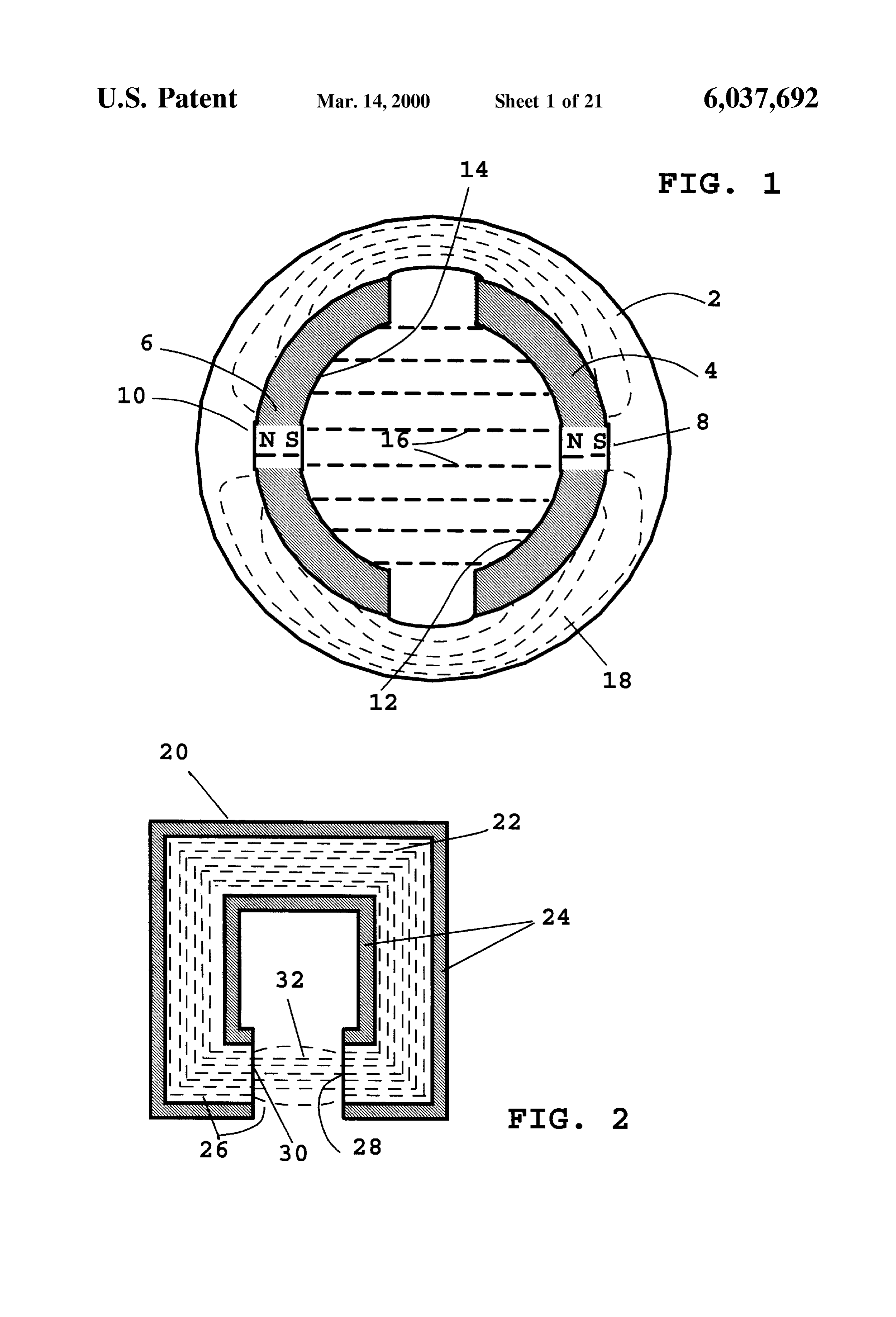
This procedure results in an increase in the amount of Source of desirable heat that can be used to maintain a useful torque that can be delivered by a given permanent magnet battery temperature or for interior heating applications. motor at a given voltage and RPM value. This increase in BRIEF DESCRIPTION OF THE DRAWINGS torque translates directly to an increase in power to weight ratio. This increase in torque also reduces the amount of 65 FIG. 1 shows the magnetic flux paths in the stator gearing needed to produce a given torque output from a gear assembly of a brush timed permanent magnet DC electric reduction box. motor.
Page 28
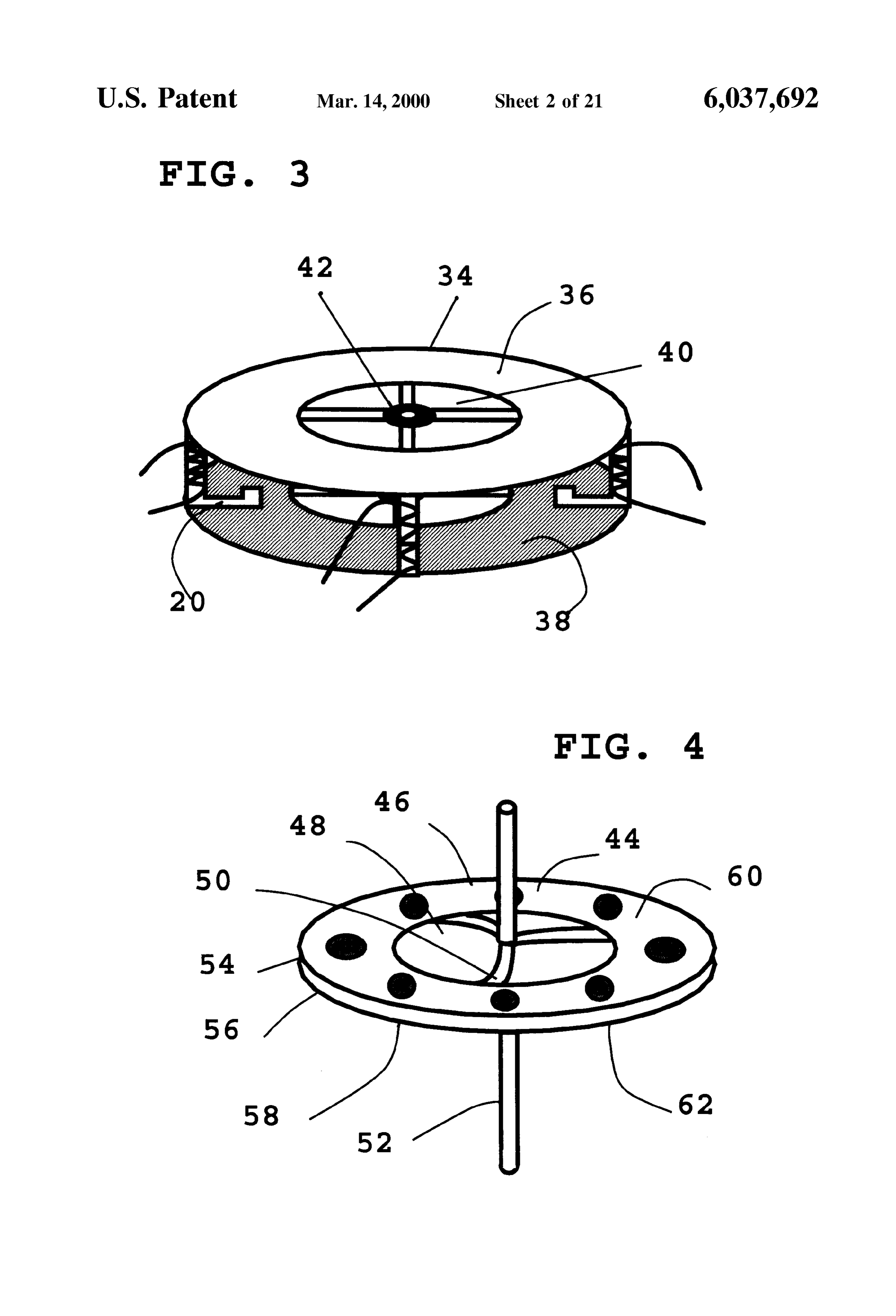
FIG. 2 shows the magnetic flux path of one of the stator material in the periphery to provide mechanical power by electromagnet assemblies of this invention. Switch-reluctance.
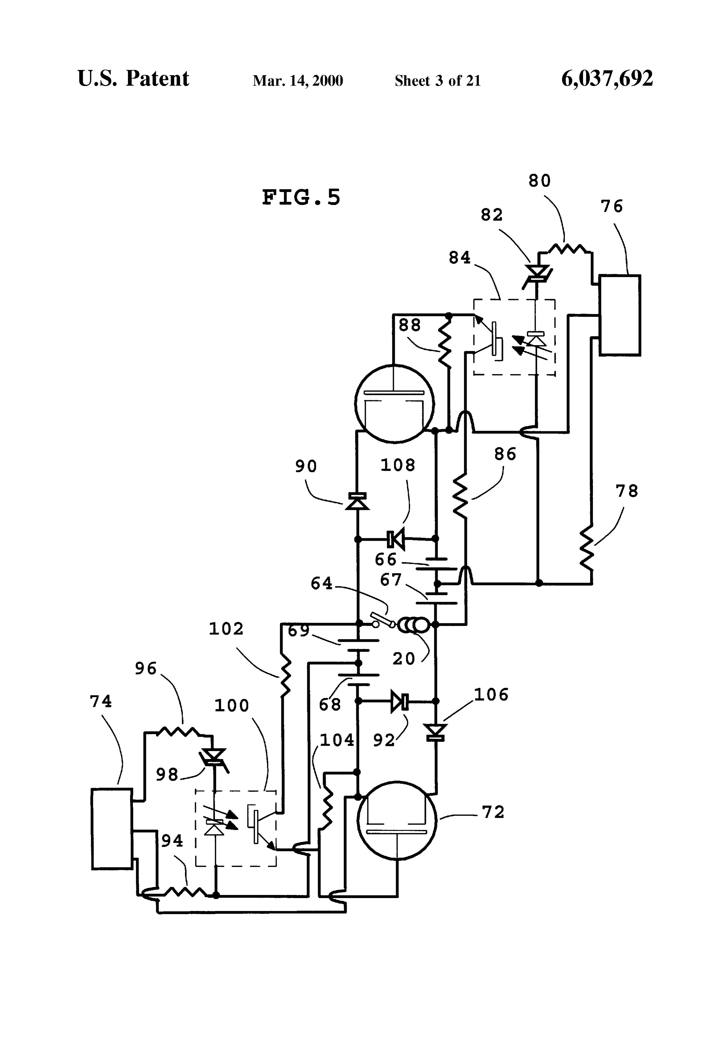
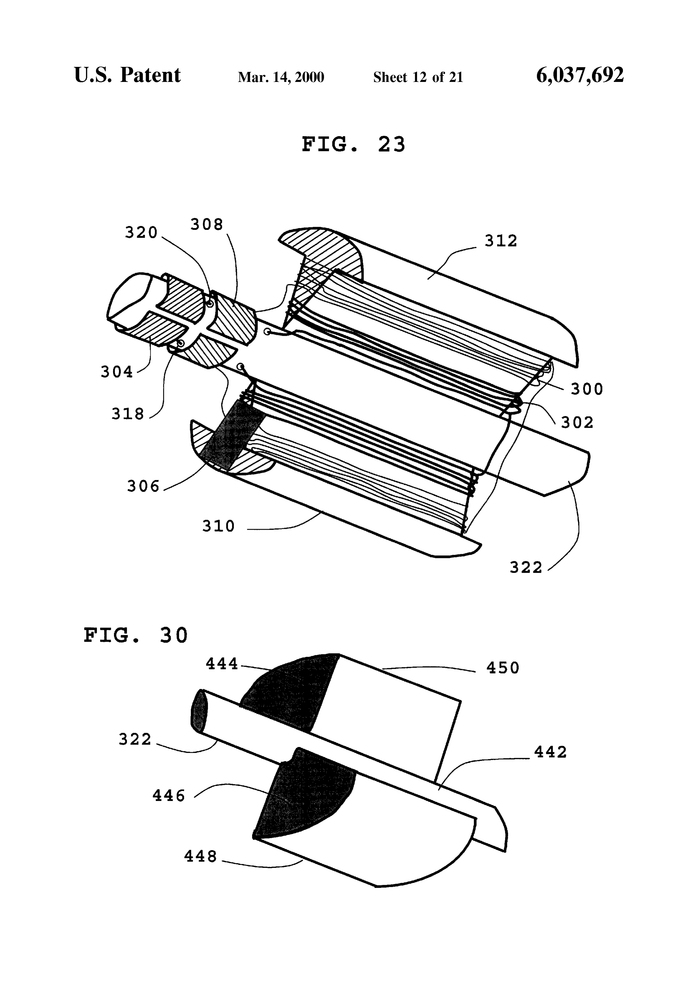
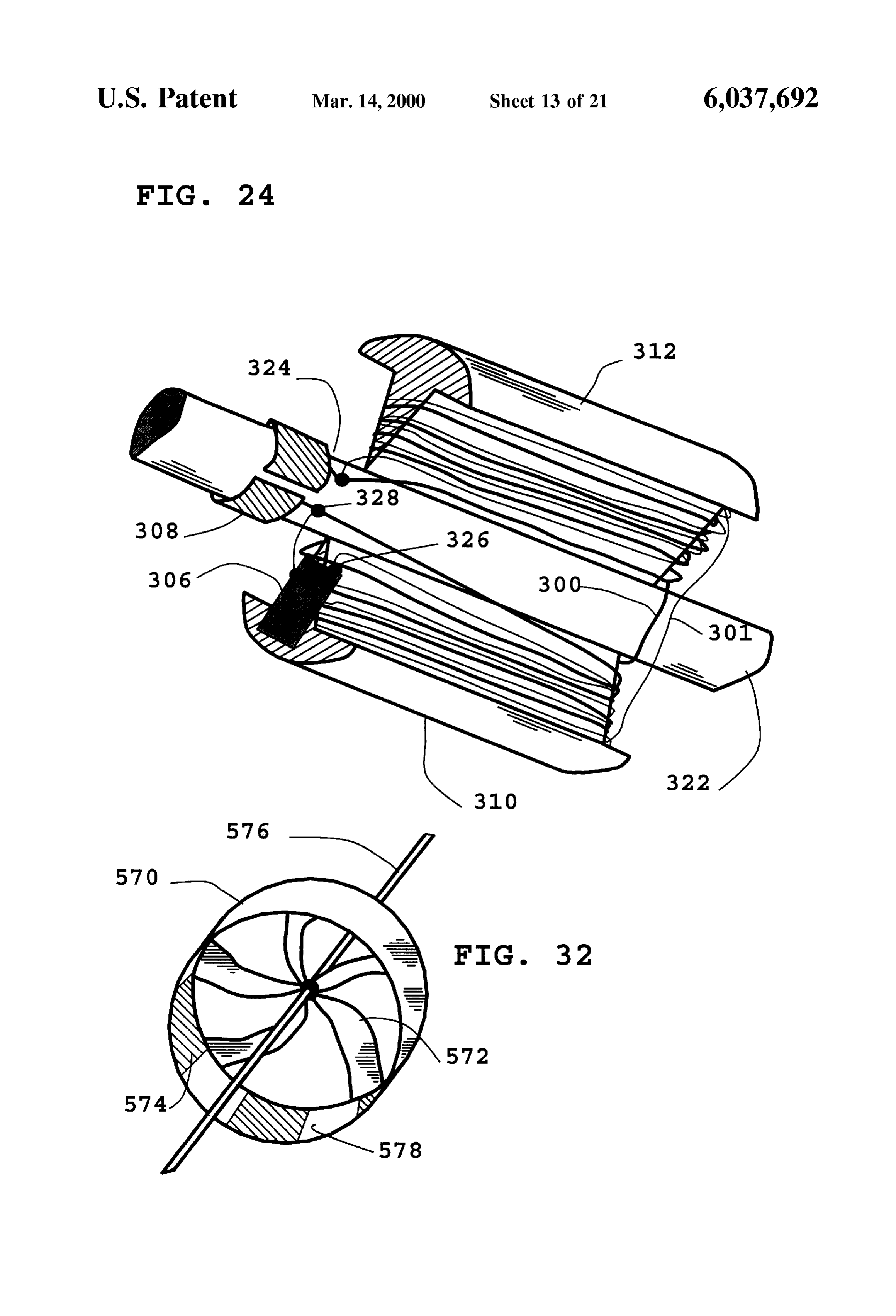
FIG. 3 shows a detailed drawing of the stator portion of FIG. 23 shows the rotary portion of a brush timed the motor of this invention. permanent magnet motor having two Separate electromagnet FIG. 4 shows the rotary disc portion of the motor of this windings wrapped around the core each having their own Set invention with built in impeller. of commutators, and a centrifugal Switch. FIG. 5 shows a diagram of circuitry needed to drive the FIG. 24 shows the rotary portion of a brush timed high-powered DC turbofan cooled motor of this invention. permanent magnet motor having added windings which are FIG. 6 shows a Stator electromagnet having multiple made from thicker wire than the first Set along with a windings of differing wire diameter for increasing motor centrifugal Switch.
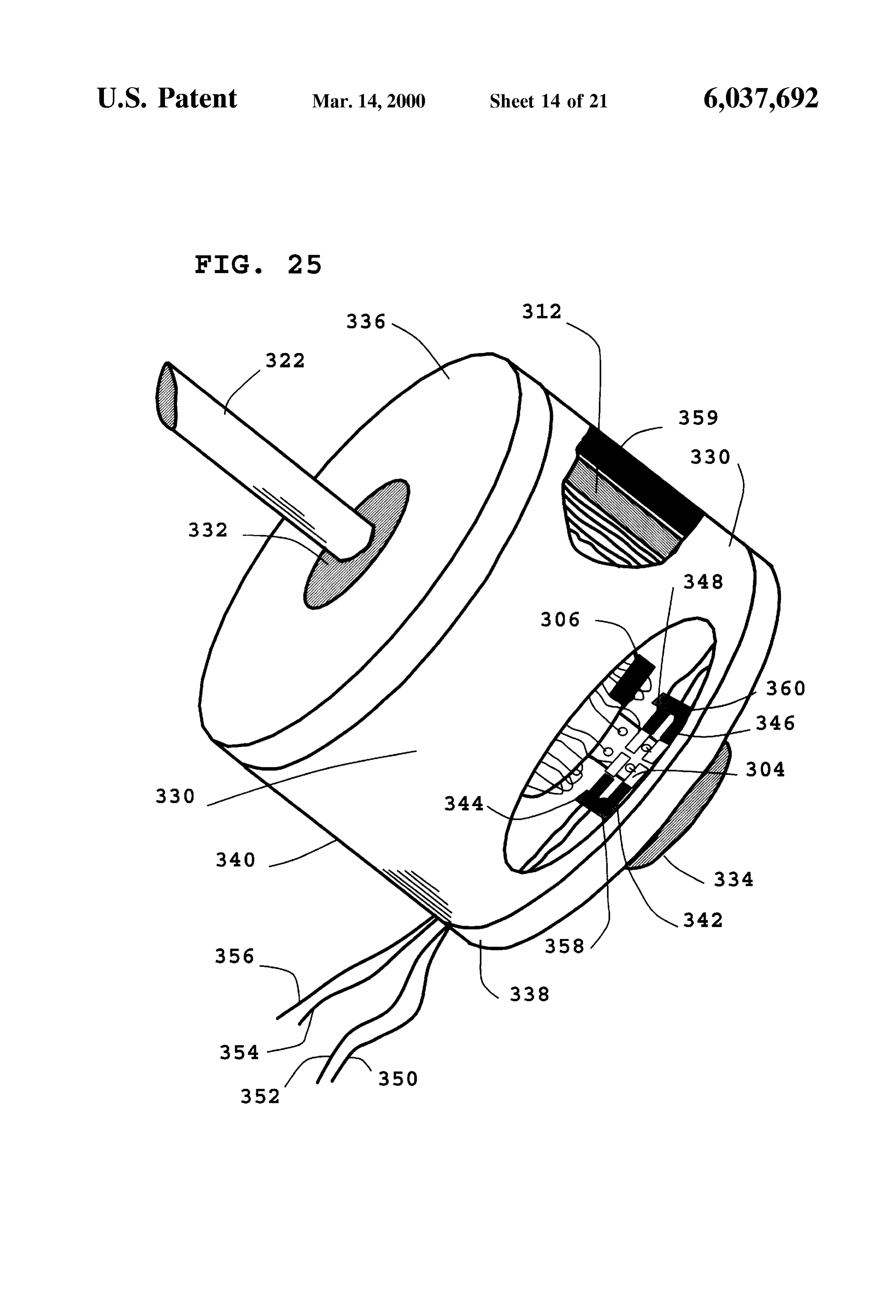
torque at high RPM values. FIG. 25 shows a brush timed permanent magnet electric FIG. 7 shows an overall diagram of the high-powered DC windings,motor employing a rotor having two separate electromagnet turbofan cooled motor of this invention. and a centrifugal Switch for activating both Sets of windings at a pre-Set value.
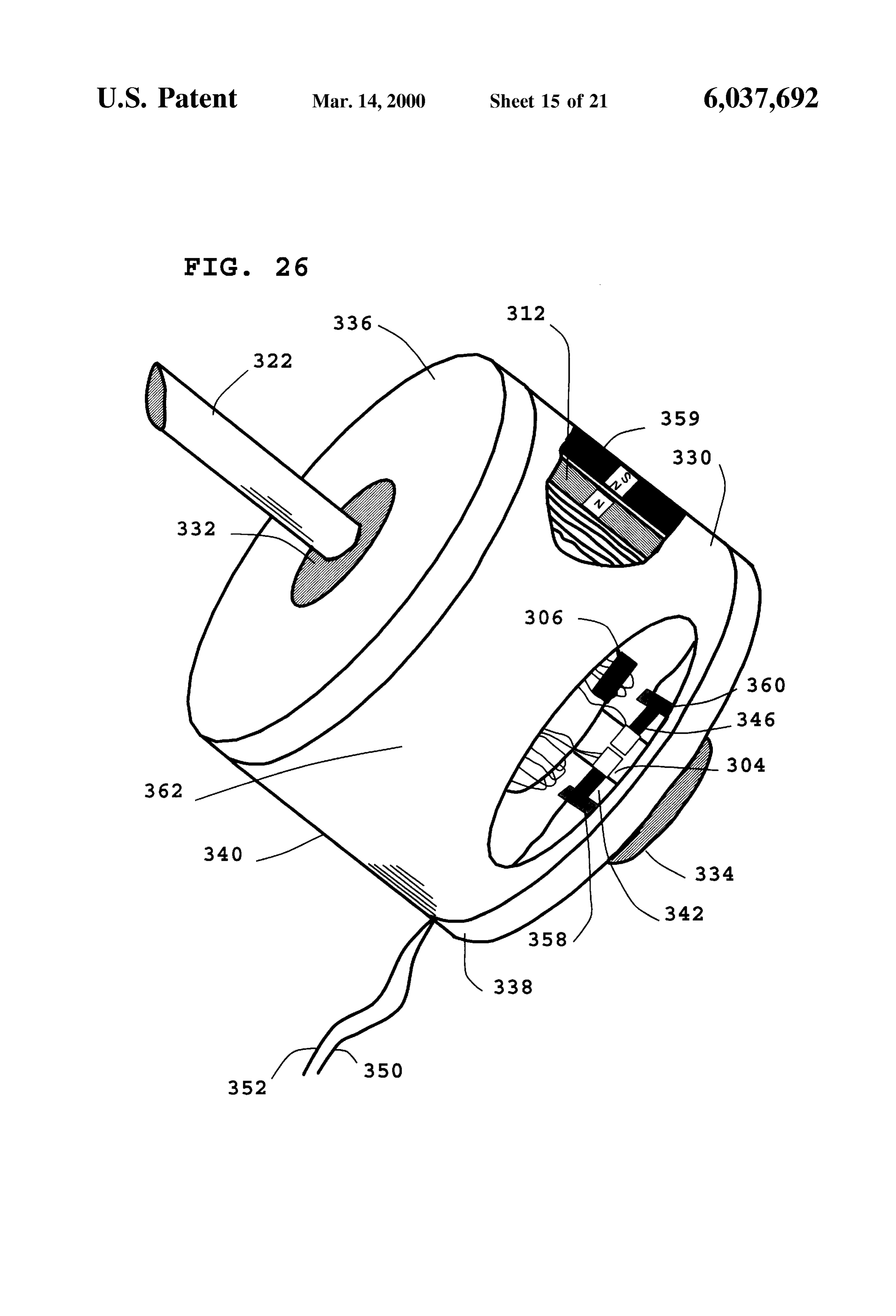
FIG. 8 shows an overall diagram of the high-powered DC 15 FIG. 26 shows a brush timed permanent magnet DC turbofan cooled motor of this invention having two rotor electric motor having added windings which are made from discS mounted onto the same central shaft. thicker wire than the first set. FIG. 9 shows a diagram of the armature of the motor of FIG. 27 shows the stationary electromagnet portion of a this invention having short flexible blades emanating radi typical brushleSS permanent magnet D.C. electric motor ally from the edge of the rotor which allows for adequate having added electromagnet windings which are made from cooling under low RPM values but which limits air flow thicker wire than the first set.
under high RPM values to prevent excess power consump FIG. 28 shows the stationary electromagnet portion of a tion.
typical brushleSS permanent magnet DC electric motor hav
FIG. 10 shows a current sensing device which prevents 25 ing electromagnet windings made from twisting two Strands accidental demagnetization of the rotor permanent magnets of electromagnet wire together.
at low Speeds. FIG. 29 shows the stationary electromagnet portion of a FIG. 11 shows the rotary portion of the motor of this typical brushleSS permanent magnet DC electric motor invention having a toothed edge for engagement to a gear or employing two sets of electromagnet windings which are cog belt. electrically isolated from each other. FIG. 12 shows the rotary portion of the motor of this FIG. 30 shows the permanent magnet rotary portion of a invention consisting of a disc having a Smooth Surface. typical brushless D.C. electric motor. FIG. 13 shows the rotary portion of the motor of this FIG. 31 shows a typical D.C. brushless electric motor invention consisting of a disc having a roughened Surface to employing added electromagnet windings which are made increase airflow. 35 from thicker wire than the first set along with an interlock
FIG. 14 shows the top view of an optical encoder disc mechanism.
along with photocell gates to provide timing for the high FIG. 32 shows the rotary portion of a large diameter power motor of this invention. brushleSS D.C. electric motor consisting of a central turbofan FIG. 15 shows a tilted view of an optical encoder disc and 40 portion and permanent magnets around the periphery. photocell gate used to provide timing for the high power FIG. 33 shows a large diameter brushless D.C. electric motor of this invention. motor having a rotary portion consisting of a central turbo FIG.16 shows a side view of the high power motor of this fan and permanent magnets around the periphery, and a invention including a Small generator on the shaft for Speed centrally located Star Shaped electromagnet. Sensing, Speed Sensing circuitry, optical timing circuitry, and 45 FIG. 34 shows a large diameter brushless D.C. electric amplification circuitry. motor having a rotary portion consisting of a central turbo FIG. 17 is a Schematic diagram showing optical timing fan and permanent magnets around the periphery, a centrally circuitry integrated with transistor amplification circuitry located Star shaped electromagnet, and added gear teeth which provides power to the electromagnets in the motor of around the outside periphery.
this invention. 50 FIG. 35 shows a large diameter brushless D.C. electric FIG. 18 shows an electromagnet assembly including fan andhaving motor a rotary portion consisting of a central turbo Switching circuitry having thick wire wrapped around the located Star shaped magnets permanent around the periphery, a centrally electromagnet, and teeth for engagement core to a first tap, and thinner wire wrapped over the thick to a cog belt around the outside periphery. wire to a Second tap.
FIG. 19 shows a sectional view of the edge of the disc 55 FIG. 36 shows a large diameter air cooled electric motor traveling through an electromagnet gap including permanent of this invention employed in a vehicle hub drive system having a Steel rim, permanent magnets attached to the inside magnets Sandwiching a flat Steel Spoke. portion, a Star shaped electromagnet assembly which is FIG. 20 shows a multitap electromagnet having the tap bolted onto the vehicle frame, and large Structural air Selection controlled by a relay which receives a voltage 60 moving Spokes for connecting the outer rim portion to an Signal from a Small electric generator. axle assembly.
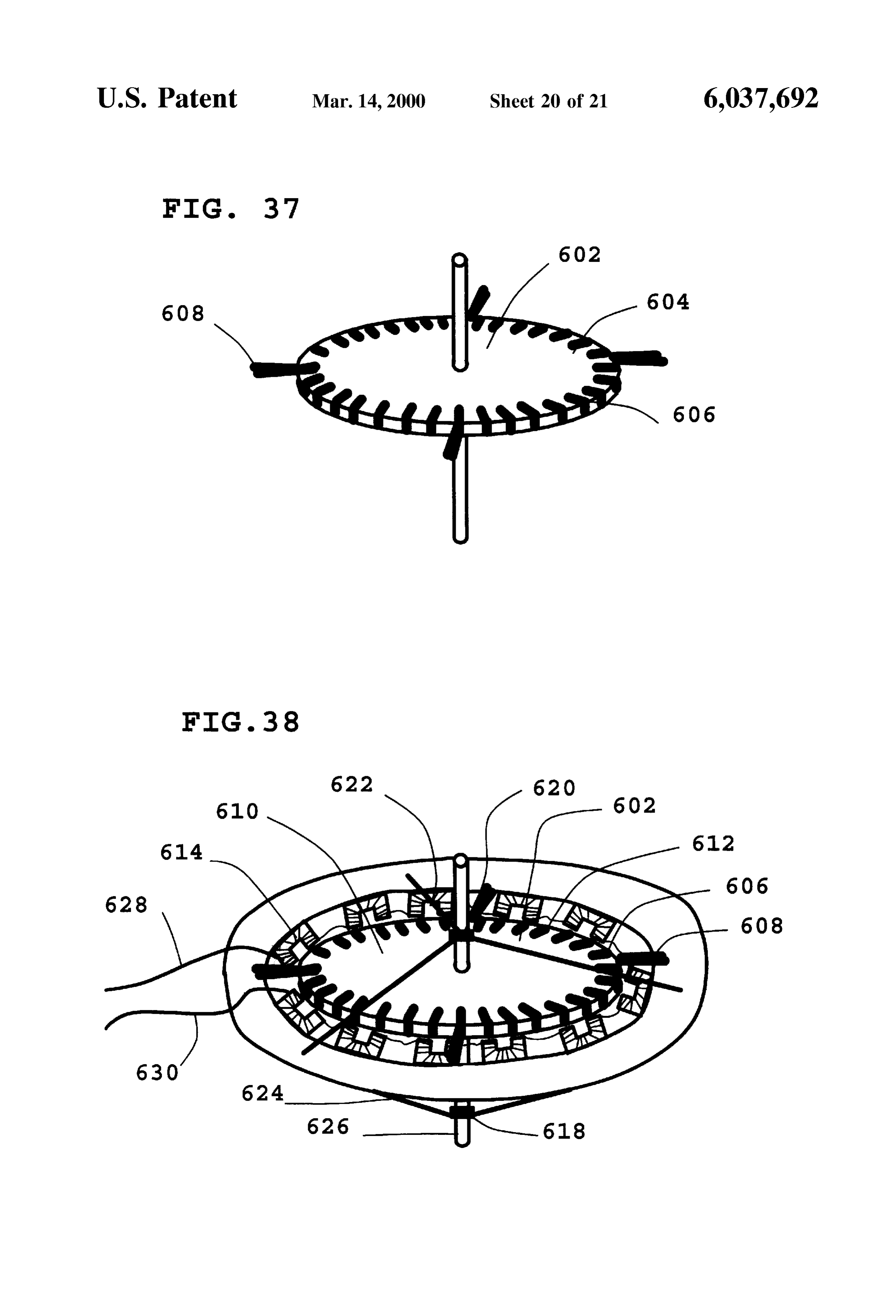
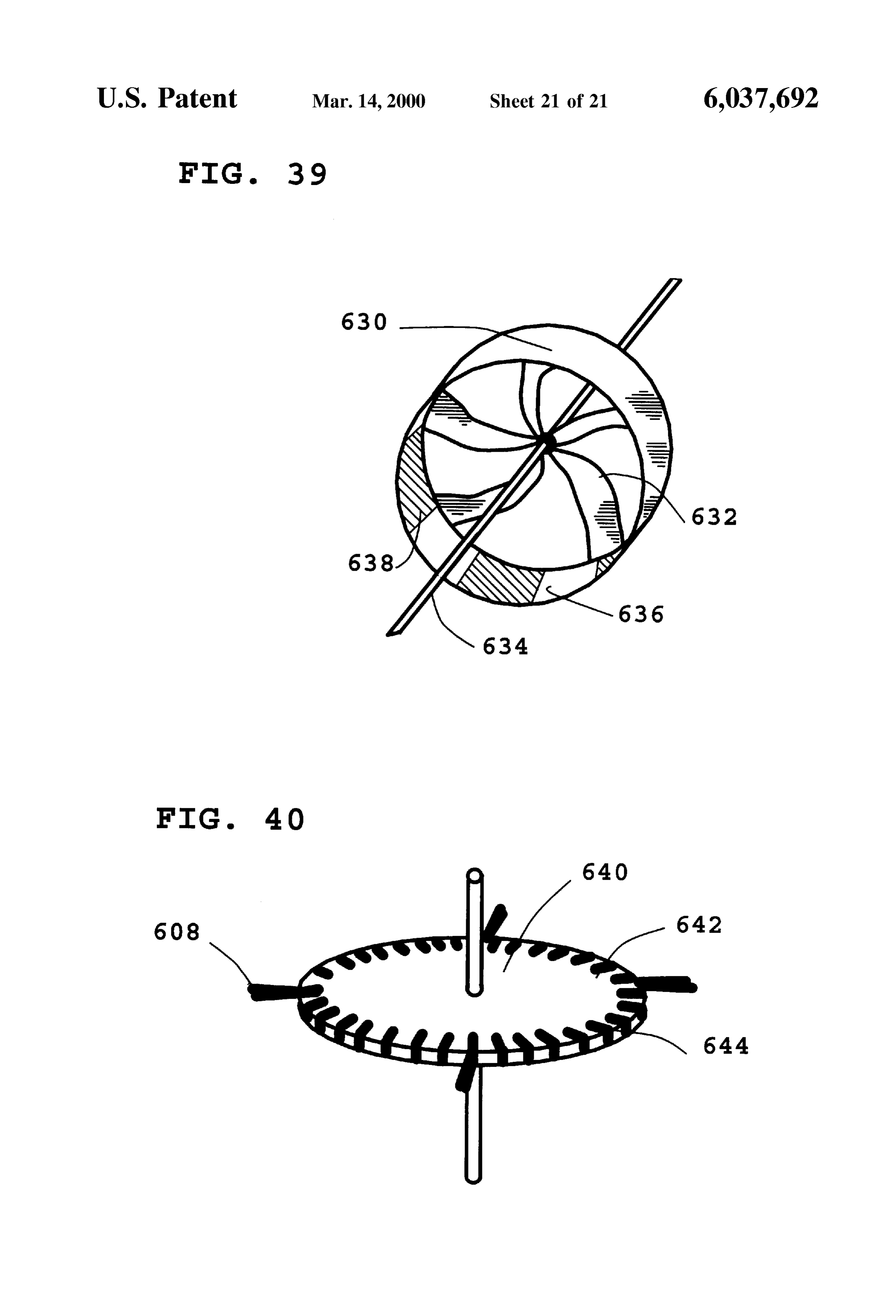
FIG. 21 shows a smooth rotary disc rotor of this invention FIG. 37 shows the rotary portion of a large diameter incorporating a non-magnetizable high permeability mate brushleSS D.C. motor consisting of a planar disc having rial in the periphery to provide mechanical power by Switch permanent magnets about the periphery in a radial direction, reluctance. 65 and fixed air moving Vanes protruding from the edge. FIG. 22 shows a rotary disc rotor having a rough texture FIG. 38 shows a large diameter brushless motor consist Surface incorporating a non-magnetizable high permeability ing of a planar disc rotor having permanent magnets about
Page 29
the periphery in a radial direction, electromagnets pointing electromagnet, and then reverses the energization applied to inward toward the edge of the disc, and fixed air moving coil 24 to push the permanent magnet out of the electro Vanes protruding from the edge of the disc which move air magnet 20 and to pull the next permanent magnet forward. over the electromagnets. When permanent magnet 54 passes the Hall effect sensor 76, FIG. 39 shows the rotary portion of a large diameter power from battery 66 flows through resistors 78 and 80 and brushleSS D.C. electric motor consisting of a central turbofan Zener diode 82 to activate opto-isolator 84. The phototrans portion and non-magnetizable high permeability material istor portion of opto-isolator 84 is wired to the gate portion around the periphery. of MOSFET power transistor 70 through biasing resistor 86. FIG. 40 shows the rotary portion of large diameter brush Biasing resistor 86 in turn is connected to the positive side leSS D.C. electric motor consisting of a planar disc having of battery 67. Resistor 88 connects the gate of MOSFET non-magnetizable high permeability material embedded on power transistor 70 to the negative side of battery 66 and Serves two purposes. One purpose is to discharge the gate the outside periphery, along with added air moving Surfaces. capacitance of transistor 70 for rapid turn off; and the other DESCRIPTION OF THE INVENTION purpose is to divide the battery Voltage to the gate to allow 15 for low gate turn-on Voltages with relatively high battery
FIG. 1 shows the open magnetic circuit in the Stator Voltages.
portion of a traditional permanent magnet DC motor. Thus, when Hall effect sensor 76 is activated by perma Encased in thick Steel housing 2 are permanent magnets 4 nent and 6 having opposite poles 8 and 10 against housing 2. Also Powermagnet 54, transistor 70 is turned on with full power. from batteries 66 and 67 is then delivered to elec shown are permanent magnet poles 12 and 14 which are tromagnet 20 through diode 90. Electromagnet 20 then aligned with each other acroSS air gap 16. Also shown are moves the wheel forward by pulling permanent magnet 54 lines of magnetic flux 18 which travel both through the into its field. When permanent magnet 54 approaches its motor housing 2 as well as through air gap 16. Thus, the equilibrium position, Hall effect sensor 76 is shut off. The completion of flux lines 18 from permanent magnets 4 and unused magnetic energy Stored in the electromagnet shows 6 requires a thick magnetic motor housing 2 as part of the 25 up as a reverse EMF spike. Diode 90 isolates transistor 70 magnetic circuit. from this spike. Diode 92 then shunts this spike into batteries FIG. 2 shows the flux path produced by stator electro 67 and 68 to give them a slight charge. Permanent magnet magnet 20 in the electric motor of this invention. Stator 54 passes by Hall effect sensor 74, Switching power from electromagnet 20 consists of a magnetic core 22 in the shape battery 68 though resistors 94 and 96 and Zener diode 98 to of a “C” which is wound with electromagnet wire 24. When activate opto-isolator 100. The phototransistor portion of electromagnet windings 24 are energized, magnetic flux 26 opto-isolator 100 is wired to the gate portion of MOSFET is generated in accordance with the right-hand rule of power transistor 72 through biasing resistor 102. Biasing electrically induced magnetism. The magnetic flux 26 that is resistor 102 in turn is connected to the positive side of generated is contained within core 22 and emerges from pole battery 69. Resistor 104 connects the gate of MOSFET faces 28 and 30. With the electromagnet geometry shown in 35 power transistor 72 to the negative side of battery 68 for the FIG. 2, the magnet flux generated remains entirely within air purposes of draining the gate capacitance of MOSFET gap 32 of the electromagnet 20. The electromagnet geometry power transistor 72 when the gate Voltage is shut off and of this invention is based on a Rowland ring. ARowland ring divides the gate Voltage used to maintain a Safe operating was named after J. H. Rowland who made use of it in his level at the gate. Thus when Hall effect sensor 74 is activated experimental work on electricity and magnetism. A Rowland 40 by permanent magnet 54, MOSFET power transistor 72 is ring consists of a torroidal coil of wire wrapped around an turned on with full power. Power from batteries 68 and 69 iron core. The unique property of a Rowland ring is that the is then delivered to electromagnet 20 through diode 106, in magnetic flux generated is confined wholly to the core. The the opposite direction from that Supplied through transistor electromagnet design shown in FIG. 2 is a Rowland ring 70. Electromagnet 20 moves the rotor forward by pushing which has been modified into an electromagnet by removing 45 permanent magnet 54 out of its field, and pulling the next a Section to produce an air gap having opposite magnet poles Successive permanent magnet into the field. Once permanent on each side. magnet 54 has been sufficiently moved out of the field of FIG. 3 shows the stator portion 34 of the high powered air electromagnet 20, Hall effect sensor 74 shuts off power to cooled DC motor of this invention. Several electromagnets the circuit. Stored magnetic energy left in electromagnet 20 20 are mechanically fastened to end plates 36 and 38. Also 50 shows up as a back EMF spike which is isolated from shown is an opening 40 in end plate 36 which allows air to MOSFET power transistor 72 by diode 106 and is shunted flow through the motor for the purposes of cooling. Also across diode 108 into batteries 66 and 67, thus completing shown is a bearing 42 for the purposes of providing a the cycle.
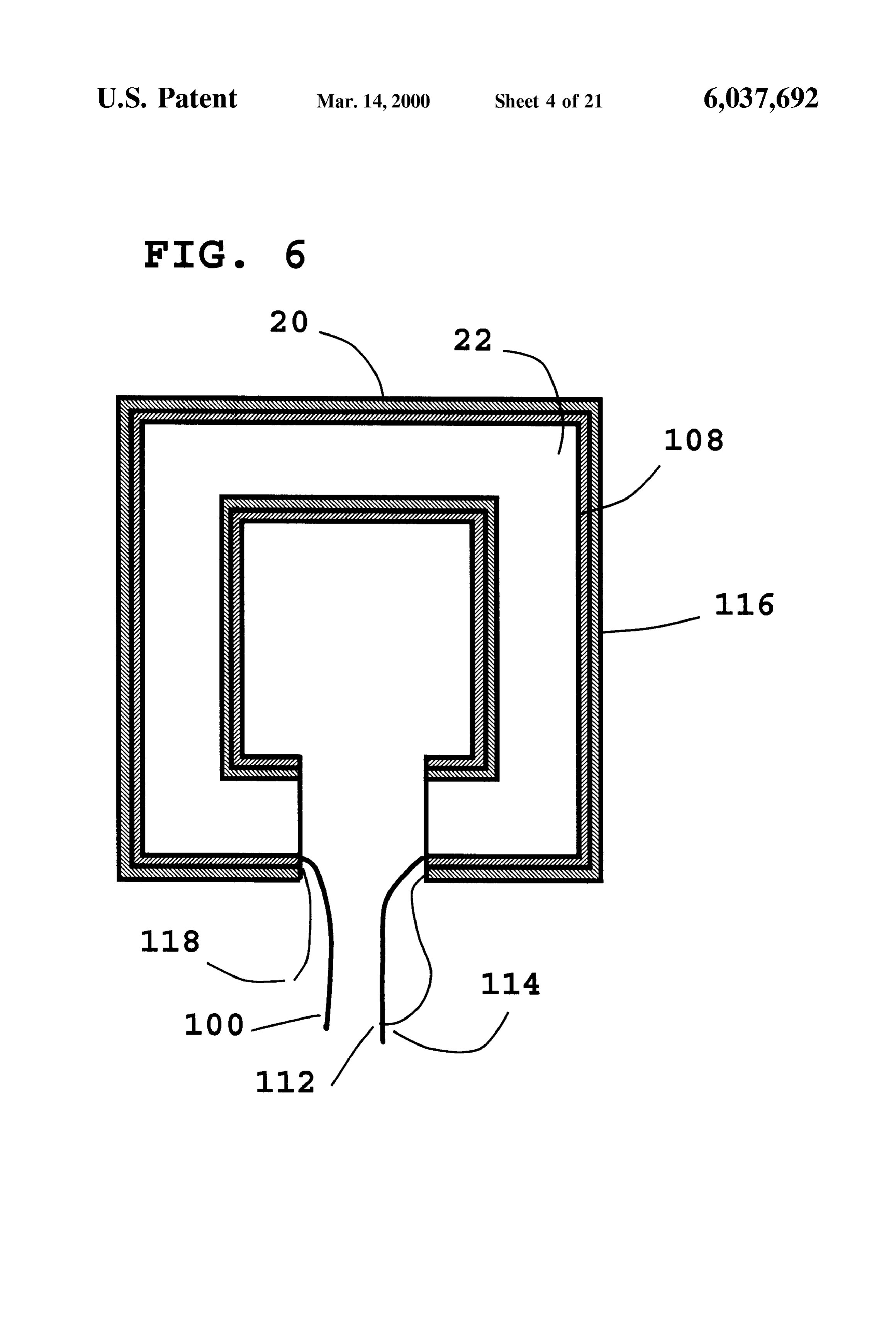
mechanical Surface for Supporting the rotatable motor shaft FIG. 6 shows one of the stator electromagnets 20 of the of the rotor portion. 55 high-powered turbofan cooled DC motor of this invention. FIG. 4 shows the rotary disc portion of the motor of this Electromagnet 20 consists of a laminated iron core 22 in the invention 44 which consists of an outer portion 46 and an shape of a “C” which is wrapped with a single layer of heavy inner turbofan portion 48. Inner turbofan portion 48 consists gauge electromagnet wire 108 having ends 100 and 112. End of individual blades 50 connecting a central axle 52 to edge 112 is then electrically connected to one end 114 of a lower portion 46. Edge portion 46 has Several permanent magnets 60 gauge electromagnet wire 116 which is wound in a Second 54 mounted having their magnetic pole faces 56 and 58 on layer over the heavy gauge wire to give a free exposed end opposite sides 60 and 62 of outer disc portion 46. 118.
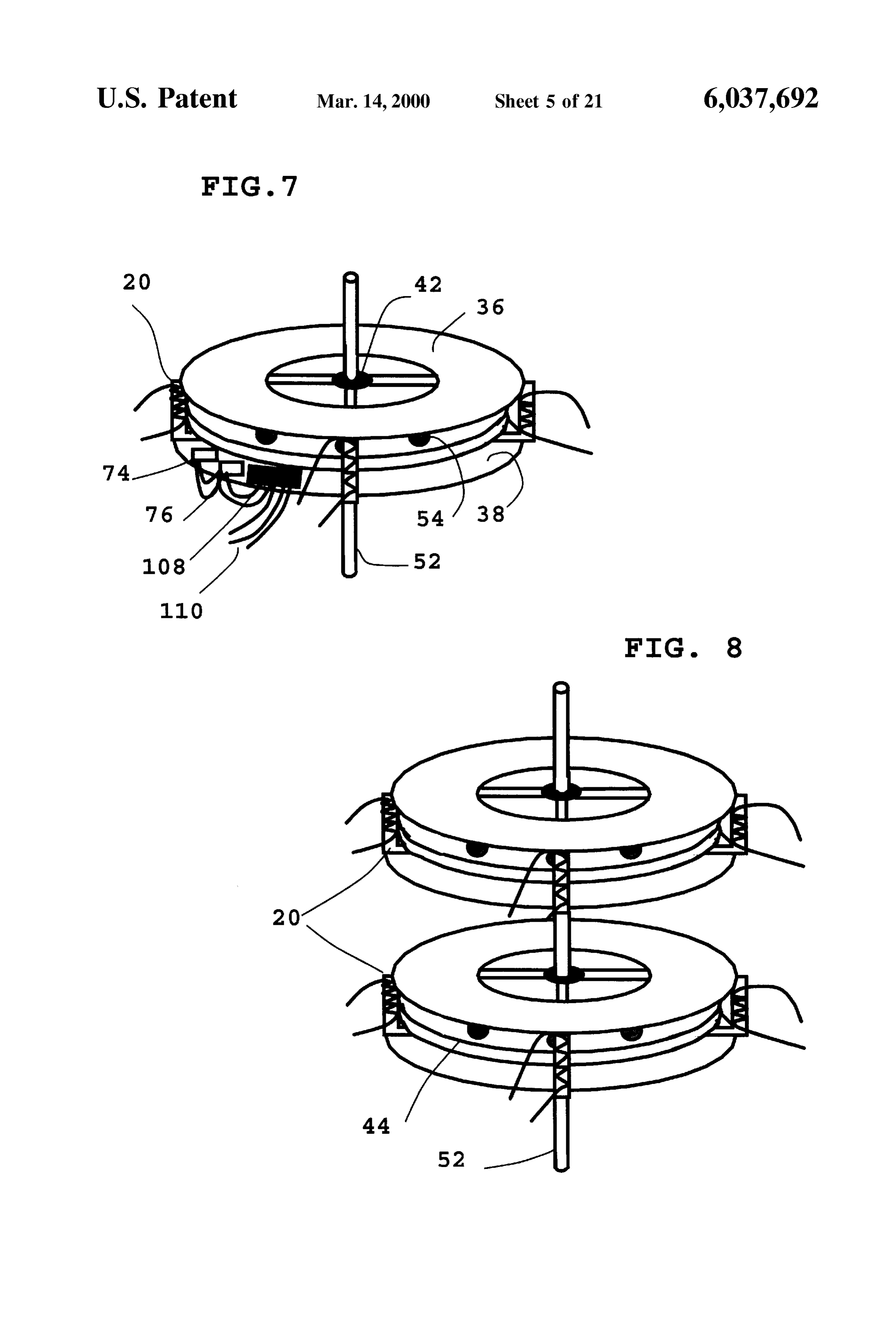
FIG. 5 shows a circuit diagram for properly timing and FIG. 7 shows a diagram of the complete motor of this Supplying power to the Stator electromagnets of this inven invention. Rotor disc 44 along the central shaft 52 is tion in order to drive the rotor. The circuit serves to initially 65 Surrounded by electromagnets 20 Straddling the edge of disc energize the coil of electromagnet 20 in one direction to pull 44 in alignment with permanent magnets 54 in the rotary an adjacent permanent magnet into the field of the disc portion. Further employed are bearings 42 in end plates
Page 30
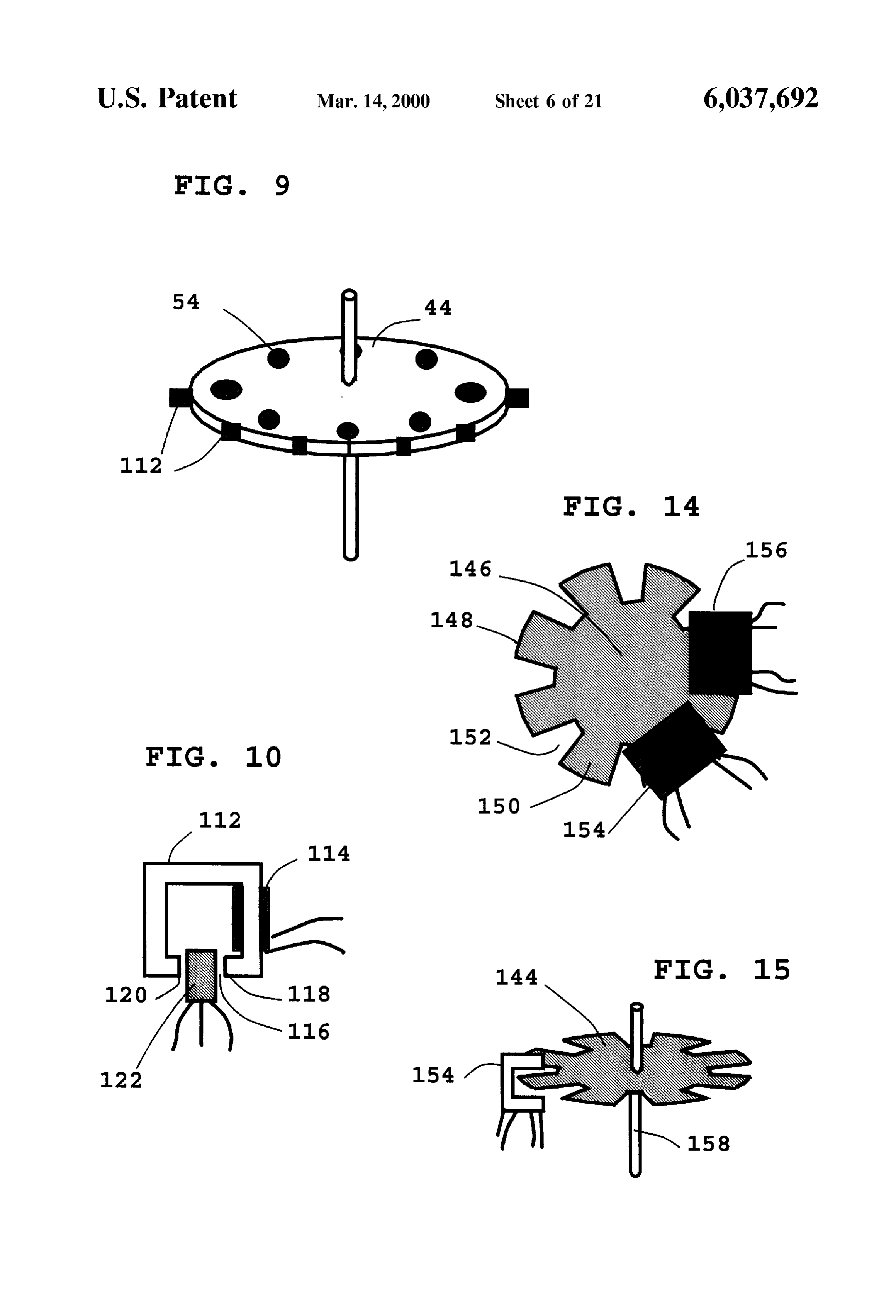
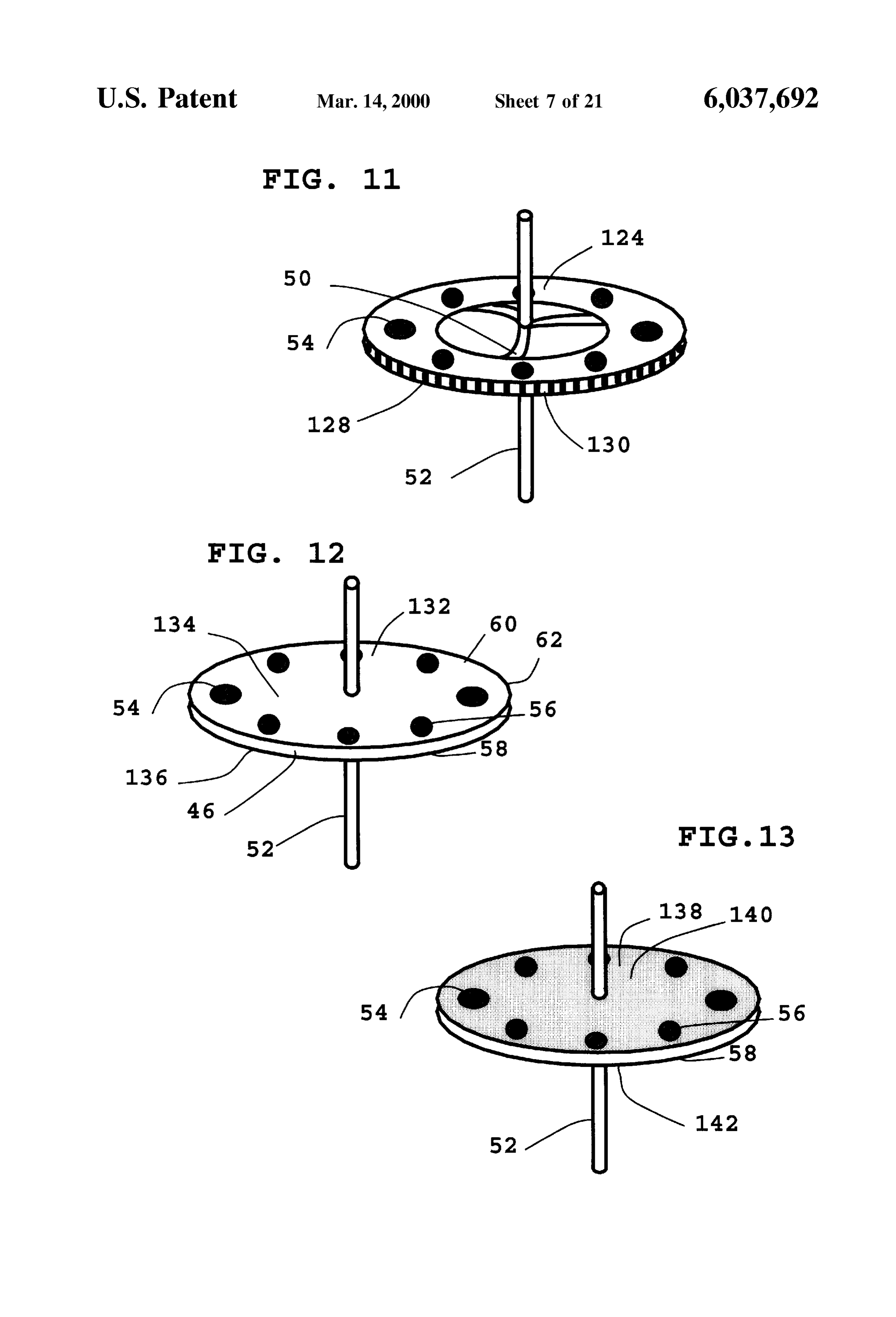
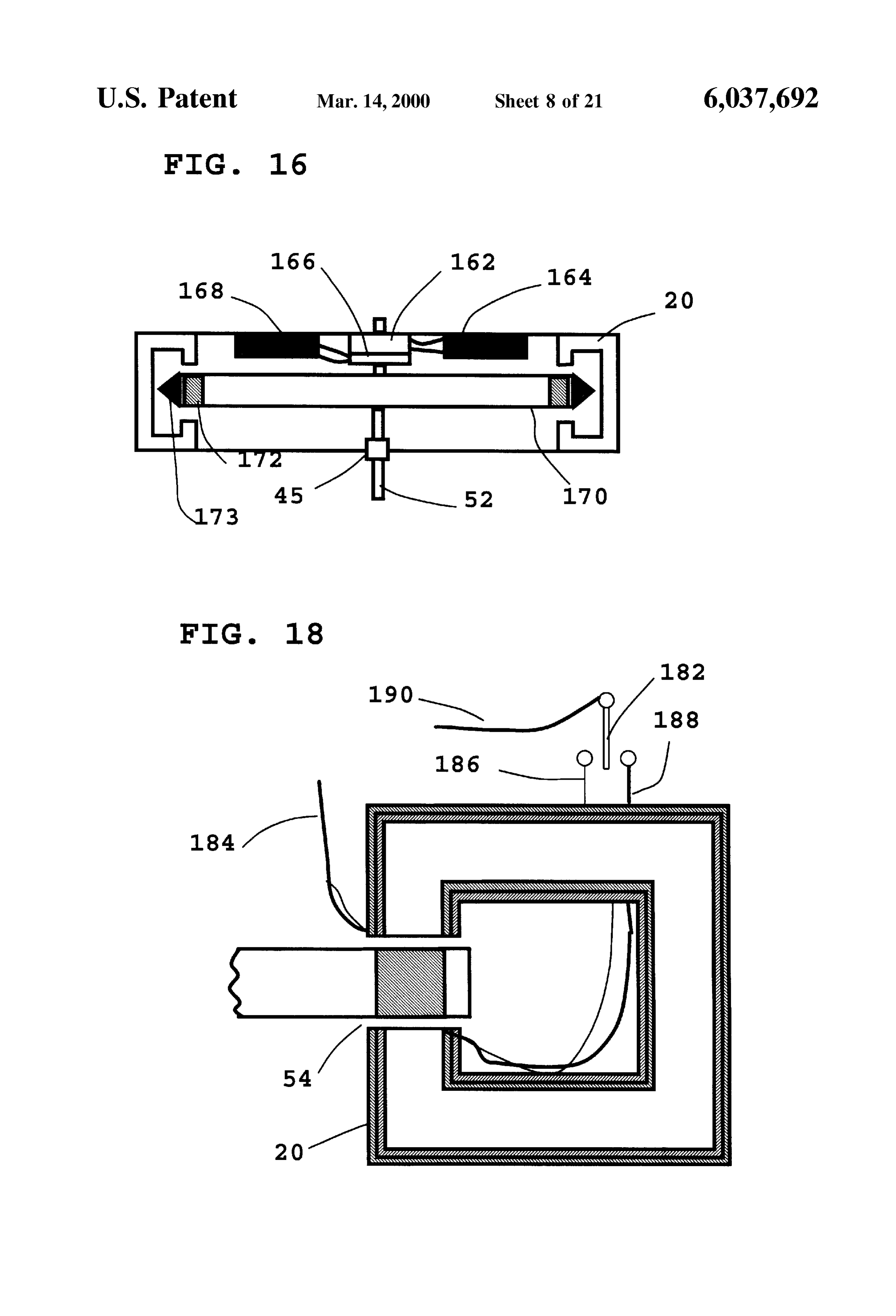
36 and 38. End plates 36 and 38 together with electromag FIG. 14 shows the top view of an optical encoder disc 144 nets 20 provide the stationary part of this motor. Hall effect having a central portion 146 and an edge portion 148. Edge sensors 74 and 76 provide the timing for amplification portion 148 consists of alternating opaque areas 150 and circuitry 108 and is distributed to electromagnets 20 by transparent areas 152. Also shown are two photocell gates wires 110. 154 and 156 used to provide a signal for timing purposes. FIG. 8 shows two discs 44 on a single shaft 52. Each disc FIG. 15 shows a tilted view of optical encoder disc 144 is driven by its own set of electromagnets 20. This geometry and photocell gate 154. Also shown is shaft 158 which is provides high torque in a package having a limited diameter directly fastened to the end of the motor shaft (not shown). and also results in an overall reduction in inertia mass. FIG. 16 shows a side view of the disc rotor air cooled FIG. 9 shows a rotor disc 44 having permanent magnets motor of this invention. Disc rotor motor 160 is shown in 54 mounted in the same configuration as those shown in complete form. This particular motor includes a Small elec FIG. 4. The disc of FIG. 9 does however have a solid center tric generator 162 which Senses the rotor Speed by generat and fan blades 112 along the edge to provide direct cooling ing a Voltage which is proportional to the Speed. Generator to the electromagnets (now shown). Fan blades 112 may be 162 is of the permanent magnet type and therefore requires made of a flexible material Such as mylar, kapton, or other 15 no field windings and therefore no input power. Such a polymer film. The flexible fan blades allow for high air flow generator can be either of the DC output type, or conversely at low RPM values and reduce aerodynamic drag at high the AC output type. In the case of permanent magnet DC RPM values. output generators, a simple permanent magnet motor will FIG. 10 shows an example of current limiting circuitry often Suffice. Although many Speed Sensing methods may be Suitable for preventing accidental demagnetization of rotor employed, the generator offers the best protection against permanent magnets 54 (not shown). A Small laminated iron failed circuit components. Such failure can cause premature core 112 having slot 116 is provided with several turns of shunting of electromagnet windings resulting in the potential heavy gauge wire 114. Magnetic poles 118 and 120 are for demagnetization of rotor permanent magnets. The gen formed when current flows through wire 114. Into slot 116 erator absolutely will not put out a given Voltage until a is placed a Hall effect Sensor 122 having Schmidt Triggering 25 minimum RPM value has been achieved. Failure of the Circuitry which is used to Sense the magnetic field present generator results in low or no output Voltage. This failure within gap 116. Windings 114 on iron core 112 are wired in mode will not result in premature shunting problems. Gen series with electromagnet 20 (not shown). When an unac erator 162 can be wired to a relay to either automatically ceptable amount of current flows through windings 114, the shunt electromagnet taps at a particular Speed, or interlock magnetic field generated in Small iron core 112 activates out the accidental premature shunting of electromagnet taps. Hall effect sensor 122 which grounds out the gate of the Generator 162 of motor 160 is wired to a control box 164. corresponding MOSFET power transistor providing power Control box 164 contains interlocking circuitry. Beneath to electromagnet 20 and momentarily cuts off the current. generator 162 of motor 160 is optical encoder 166. Optical The Schmidt triggering aspect of Hall effect sensor 122 is encoder 166 is mounted to motor shaft 152. The optical advantageous in Switching the power transistors on and off 35 encoder itself is shown in detail in FIGS. 14 and 15 rapidly in place of reducing the constant current flow on a previously described. Optical encoder 166 is wired to ampli continuous basis. Such Switching results in Virtually no fication circuitry 168 which amplifies the signal from optical voltage drop across circuit elements and allows the MOS encoder 166 and inputs the amplified signal into electro FET drive transistors to run cool even under current limiting magnets 20.
conditions. 40 Supported on motor shaft 52 is rotary disc 170 having In FIG. 11, rotary disc 124 consists of an outer disc portions of high permeability magnetic material 172 trans portion 126 fixedly mounted to a central shaft 52 by turbofan versing through the edge portion of disc 170. FIG. 16 blades 50. Outer disc portion 126 has permanent magnets 54 particularly illustrates the plurality of C-shaped electromag fixedly mounted into outer disc portion 126 with their nets 20 configured to define an inner annular channel 173. direction of magnetization transversing through the disc. 45 The annular edge portion of disc 170 is rotatably disposed Also shown are high and low areas 128 and 130 cut into the within in annular channel 173. In the case of a permanent periphery of outer disc portion 126. These high and low magnet motor design, high permeability magnetic material areas may be in the form of gear-type teeth or other teeth 172 consists of permanent magnets. In the case of a Switched Suitable for engaging a cog-type belt or other Suitable reluctance motor design, non-magnetizable ferrite, lami mechanical drive mechanism capable of engaging the outer 50 nated Silicon Steel, or powdered iron composite may be edge of outer disc portion 126. It should be noted that in employed. Also shown are flexible plastic fan blades 112 Some instances several electromagnets (not shown) may which provide air currents to cool electromagnets 20. Motor have to be removed to allow for mechanical coupling from end plates 36 and 38 provide Support for motor shaft 52, the edge. electromagnets 20, and motor bearings 42. The permanent FIG. 12 shows a large diameter disc-shaped rotor 132 55 magnets are disposed on the annular edge portion of disc 170 having smooth top and bottom surfaces 134 and 136 respec So that the directions of magnetization thereof transverse tively. Also shown are permanent magnets 54 in edge through disc 170. In addition, the poles of the permanent portion 46 of rotor 132. Permanent magnets 54 are mounted magnets are aligned in coupling proximity to the poles of the having their magnetic pole faces 56 and 58 on opposite sides electromagnets of the Stator.
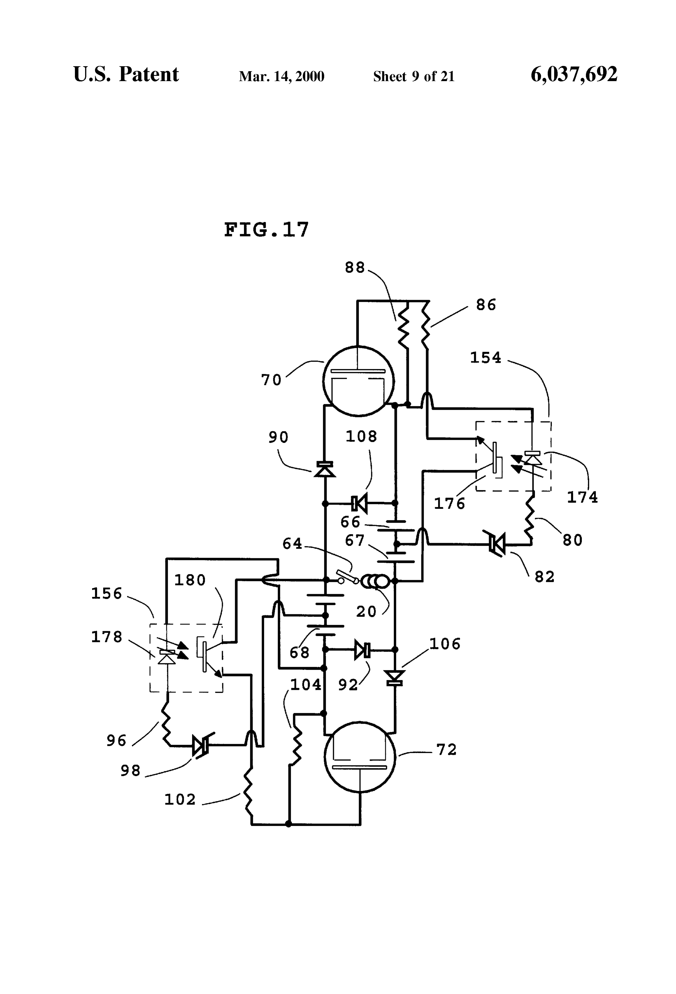
60 and 62 of outer disc portion 46. Also shown is shaft 52. 60 FIG. 17 shows optical timing circuitry integrated with FIG. 13 shows a large diameter disc-shaped rotor 138 transistor amplification circuitry which provides power to having rough textured top and bottom surfaces 140 and 142. the electromagnets in the motor of this invention. Optical Located in the periphery of disc 138 are several permanent timing gate 154 consists of a light emitting diode 174 and a magnets 54 mounted having their magnetic pole faces 56 phototransistor 176 Separated by a gap through which the and 58 on opposite sides 140 and 142 of disc 138. As usual 65 optical timing disc passes (not shown) Such optical gates are shaft 52 is used for power output and registration within the commercially available from Omron Electronics, Inc., motor. located at One East Commerce Drive Schaumburg, Ill.
Page 31
60173. Part No. EESG3 is a suitable optical timing gate, provided by electromagnet 20 and the magnetic material in although many others will work as well. The motor timing the rotor provides further propulsive force to the edge of the should be 40% on time from sensor 154, then 10% off time, rotor thereby providing mechanical power. Just before the then 40% on time from sensor 156, then 10% off time to magnetic material in the rotor (not shown) aligns itself in the complete the cycle. The motor timing itself will vary with magnetic field in the electromagnet, Optical Sensing gate the desired operating parameters, but in general the electro 156 is shut off by an opaque region of the optical timing disc magnets should be turned on slightly early with respect to (not shown). MOSFET power transistor 72 is then shut off. rotor position. Remaining Stored energy in electromagnet 20 then shows up Optical timing gate 154 has its output transistor portion as a reverse voltage spike. Diode 106 isolates MOSFET 176 wired to the gate portion of MOSFET power transistor power transistor 72 from this spike while diode 108 shunts 70. The choice of the exact MOSFET power transistor will this reverse voltage spike into batteries 67 and 68 thus depend on the requirements of the particular motor. Inter completing the cycle.
national Rectifier located at 233 Kansas Street., El Segundo, The timing of actual Switching is fundamentally different Calif. 90245 makes a variety of Hexfet MOSFET power between a disc rotor having permanent magnets and that of transistors. One should be chosen with a low on resistance, 15 a disc rotor having non-magnetizable high permeability and a rated operating Voltage of at least twice the Voltage material. In the first case, permanent magnets can be made used in the motor. The current rating capacity should be to repel as well as attract simply by changing the direction Several times the normal running current through the device. of current flowing through electromagnet 20. In the Second For example, for an operating voltage of 24 volts, IRFZ48 case of Switched-reluctance, attraction is the only net force. would be a good choice. This particular transistor has an on The two transistor circuitry however is advantageous in resistance of 0.018 ohms, a source to drain voltage of 60 driving Such Switched-reluctance motor designs in that ulti Volts, and a continuous current rating of 72 amperes. Proper lization of reverse Voltage Spikes is easily achieved which heat sinking is also recommended. Resistors 86 and 88 also reduces arcing of Switch contacts.
provide voltage dividing to the gate of MOSFET power FIG. 18 shows an electromagnet assembly 20 with an transistor 70. These values should be chosen to properly 25 SPDT Switch 182. Also shown is a common wire 184 and divide the gate Voltage, allow for quick turn on and turn off, two tapped input leads 186 and 188.188 output lead is thick and not drain excessive battery power. In general they should be chosen to provide 1 milliampere of Switching wire is the wound around the electromagnet core. Output lead 186 tap corresponding to the Second layer of wire to be current. Resistor 88 also drains the gate capacitance of wrapped around the electromagnet core and is of a thinner MOSFET power transistor 70 when the gate voltage is shut gauge than that of the first layer of wire. The output lead off by optical sensor 154. This allows for clean Switching. from SPDT switch 182 is 190. Thus output leads 184 and When mechanical switch 64 is closed, electromagnet 20 190 of electromagnet 20 form a multiple tap electromagnet is controlled by MOSFET switching transistors 70 and 72. in conjunction with SPDT switch 182. On motor start up Light emitting diode 174 is on continuously from Voltage supplied from battery 66 and is controlled by Zener diode 82 35 SPDT
switch 182 connects lead 190 to electromagnet lead
The entire length of electromagnet wire is activated.
and resistor 80. When a transparent portion of the optical The thin outer layer of wire connected to lead 186 prevents timing disc (not shown) passes by optical timing gate 154, excessive electromagnet currents from demagnetizing per LED portion 174 transmits its light to photo transistor 176. manent magnet 54. Once a Safe rotor Speed has been Phototransistor 176 turns on and power flows through volt achieved, SPDT switch 182 can be switched to electromag age dividing resistors 86 and 88. This turns on MOSFET 40 power transistor 70 thereby providing power from batteries net tap 188 thus shunting the entire length of thin electro magnet wire 186. This will substantially increase rotor 66 and 67 through diode 90 and into electromagnet 20. The power, Speed, and torque.
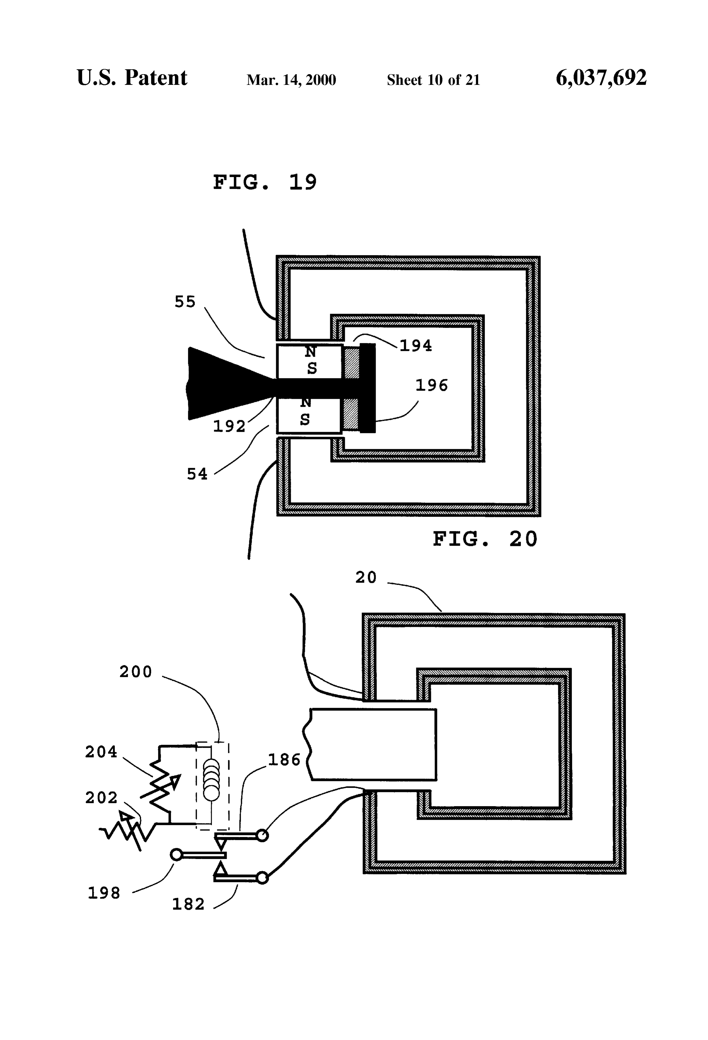
interaction of the magnetic field produced by electromagnet FIG. 19 shows a permanent magnet pair formed of 20 and the magnetic material in the rotor provides propul permanent magnets 54 and 55 Sandwiching a piece of Steel Sive force to the edge of the rotor thereby providing 45 192. Steel piece 192 forms a flat planar spoke to provide a mechanical power. Just before the magnetic material in the rotor(not shown) aligns itself in the magnetic field in the Strong mechanical bond between the inner portion of the electromagnet, optical Sensing gate 154 is shut off by an rotor and the periphery where the permanent magnets are opaque region of the optical timing disc (not shown). which located. Also shown is a piece of non-magnetic material 194 MOSFET power transistor 70 is then shut off. Remaining 50 during provides support for permanent magnets 54 and 55 running. Non-magnetic material 194 also provides
Stored magnetic energy in electromagnet 20 then shows up separation distance from T-shaped steel piece 196 thus as a reverse voltage spike. Diode 90 isolates MOSFET power transistor 70 from this spike while diode 92 shunts preventing a short circuit of their magnetic flux. this reverse voltage spike into batteries 68 and 69 giving FIG. 20 shows multiple tap electromagnet 20 interfaced to them a slight charge. AS the magnetic material in the rotor 55 relay 198 for either interlocking of or automatic Switching of passes by its equilibrium position with respect to electro electromagnet taps 182 and 186 based on a Voltage input magnet 20, optical Sensing gate 156 is turned on as a from a generator (not shown) to relay coil 200. Variable transparent portion of the optical timing disc (not shown) resistors 202 and 204 control the activation voltage of relay passes through. Light emitting diode 178 is on continuously 198.
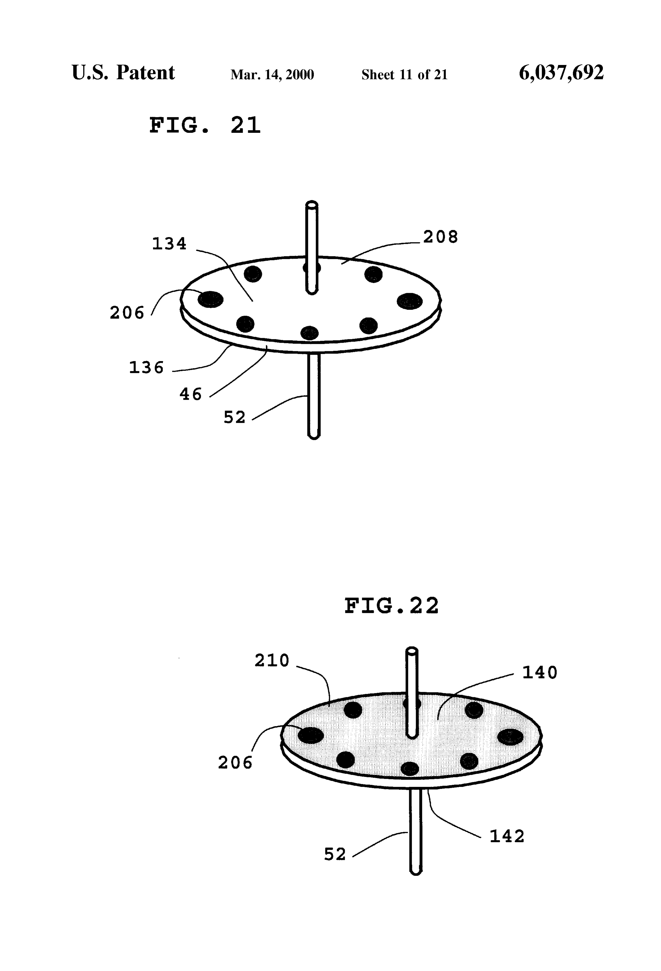
from voltage supplied from battery 68 and is controlled by 60 FIG. 21 shows a large diameter disc-shaped rotor 208 Zener diode 98 and resistor 96. Light from light emitting having smooth top and bottom surfaces 134 and 136 respec diode 178 in optical Sensing gate then activateS phototrans tively. Also shown are Sections of high permeability non istor 180 thereby supplying voltage to the gate of MOSFET magnetizable ferromagnetic material 206 in edge portion 46 power transistor 72 through voltage dividing resistors 102 of rotor 208. Also shown is shaft 52.
and 104. MOSFET power transistor 72 then turns on Sup 65 FIG. 22 shows a large diameter disc-shaped rotor 210 plying power from batteries 68 and 69 to electromagnet 20 having rough textured top and bottom surfaces 140 and 142. through diode 106. The interaction of the magnetic field Located in the periphery of disc 210 are sections of high
Page 32
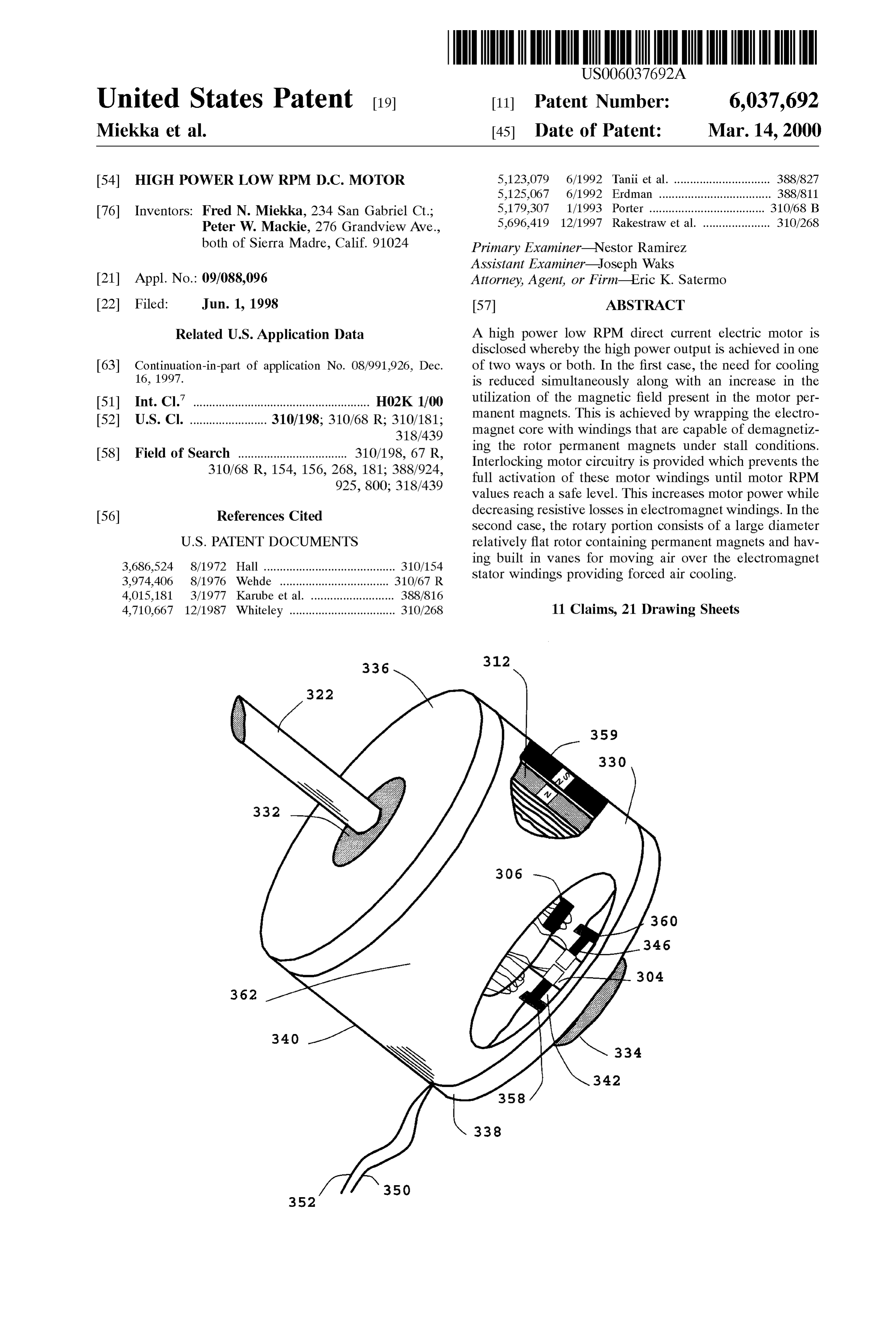
permeability non-magnetizable ferromagnetic material 206. to motor casing 340 and support bearings 332 and 334. Also AS usual shaft 52 is used for power output and registration shown are brushes 342, and 346, which are supported by within the motor. brush mounts 358 and 360. Brushes 342 and 346 provide FIG. 23 shows the rotary portion of a brush timed electric power to rotor commutator 304. Centrifugal Switch permanent magnet motor having two separate Sets of elec 306 is also shown which shunts out the thinner outer tromagnet windings 300 and 302. Inner winding set 302 electromagnet windings (not shown) in the rotational portion which is closest to shaft 322, is always connected to com of motor 362 when the RPM value reaches a pre set level. mutator 304 regardless of speed. Because of this, when Also shown is a cut away portion of electric motor 362 power is provided to commutator 304, electromagnet wind showing one of the permanent magnets 358 which is ings 302 will be activated and the motor will run at low mounted against motor casing 340. Also shown in the cut power. Once rotor RPM values reach a safe level that allow away portion of this drawing is rotor electromagnet pole for winding set 300 to be activated without the risk of face 312.
demagnetizing motor permanent magnets (not shown), cen FIG. 27 shows the stationary electromagnet portion 364 trifugal Switch 306 closes thereby connecting Outer windings of a typical brushleSS permanent magnet D.C. electric motor 300 to commutator 308. At this point, if more motor power 15 having added electromagnet windings which are made from is desired, power may be applied to commutator 308 thereby thicker wire than the first set. Electromagnet casing 340 is increasing the magnetic field of rotor electromagnet pole made from steel and therefore is capable of efficiently faces 310 and 312. Holes 314, 316, 318, and 320 in motor transmitting magnetic flux. Stator electromagnets 366 and shaft 322 are used for routing the leads of electromagnet 368 consist of laminated electrical steel to reduce eddy windings 302 under commutator 308 for connection to current losses when the motor is in operation. Stator elec commutator 304. tromagnet 366 has two pole faces 370 and 372. Pole face 370 FIG. 24 shows the rotary portion of a brush timed is attached to motor casing 340. Electromagnet pole face 372 permanent magnet electric motor having two layers of faces inward in a radial direction and is aligned with the electromagnet windings 300, and 301. Layer 300 is the first opposing inward facing electromagnet pole face 374 of layer which is made of wire having a heavier gauge than 25 electromagnet 368. Electromagnet 368 has a second pole layer 301 which is the second layer. Also shown is commu face 376 which is attached to motor casing 340. Both tator 308 which is wired to the start of winding 300 at electromagnets 366, and 368 are wrapped with two layers connection 324. The other end of winding 300 is connected 378, and 380, of electromagnet wire. The first layer of to one side of centrifugal Switch 306 and the start of winding electromagnet wire, layer 378, is of a greater thickness in 301 at connection 326. The other connection 328 to cen cross section than is the wire of second layer 380. Layers trifugal Switch 306 is connected to commutator 308 and the 378 and 380 are both wired in series with a central tap 382 remaining end of electromagnet winding 301. Also shown is which is common to both windings. Wire lead 384 is the shaft 322. When power is applied to commutator 308 by Starting lead made of thick wire for electromagnet windings brushes (not shown) current to electromagnet winding 300 is 378 and 380. This lead is the starting lead. Lead 382 is the limited by high resistance electromagnet winding 301. 35 lead at the end of thick electromagnet winding 378. This lead Under these conditions, permanent magnet motorS employ is also the starting of thinner electromagnet winding 380. ing such rotors will run at low power. Once rotor RPM Lead 386 represents the end lead of thinner electromagnet values reach a Safe level whereby shunting of electromagnet winding 380. When power is applied to leads 384, and 386. windings 301 will not result in demagnetization of motor Because the thinner electromagnet wire is in Series with the permanent magnets (not shown), centrifugal Switch 306 40 thicker wire, the current to the motor is limited to that which closes connection 326 to connection 328 thereby shunting will flow under the applied Voltage through the resistance of electromagnet winding 301. This allows electromagnet both windings in Series. When power is applied acroSS leads winding 300 to be activated with full power. This increases 382 and 384, a significantly greater amount of current flows the magnetic field of rotor electromagnet pole faces 310 and thus increasing the magnetic field between Stator electro 312. 45 magnet pole faces 372, and 374.
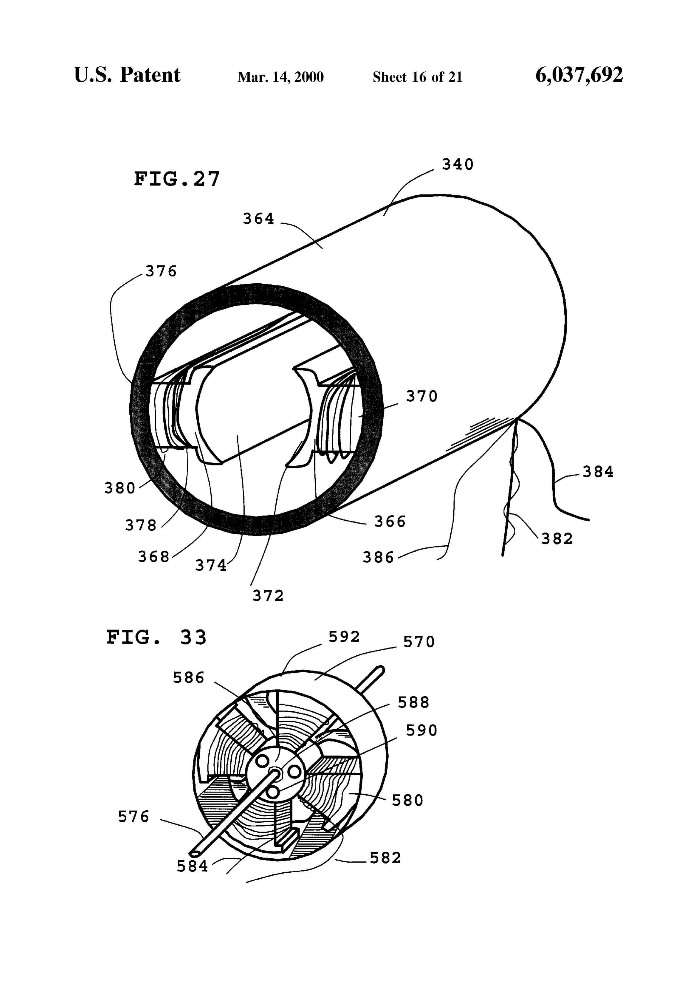
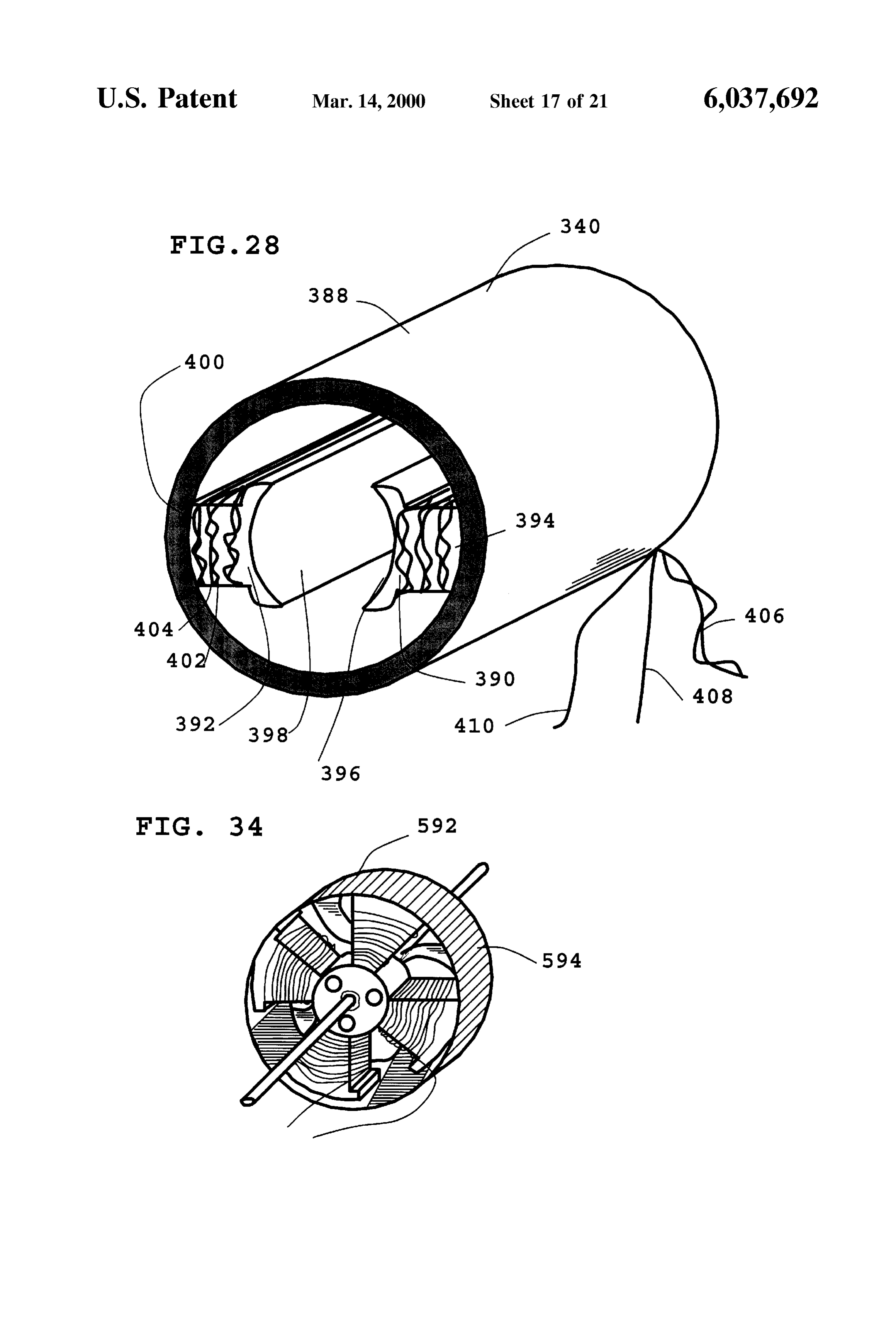
FIG. 25 shows a brush timed permanent magnet electric FIG. 28 shows the stationary electromagnet portion 388 motor 330 employing the rotor of FIG. 23. Shaft 322 of this of a typical brushleSS permanent magnet D.C. electric motor motor is rotatably supported by motor bearings 332 and 334 employing electromagnet windings which are made from in end caps 336 and 338. End caps 336 and 338 are mounted twisting two Strands of electromagnet wire together prior to to motor casing 340 and support bearings 332 and 334. Also 50 winding of stator electromagnets 390 and 392. Electromag shown are brushes 342, 344, 346, and 348, which are net casing 340 is made from steel and therefore is capable of supported by brush mounts 358 and 360. Brushes 342, 344, efficiently transmitting magnetic flux. Stator electromagnets 346, and 348 provide electric power to rotor commutators 390 and 392 consist of laminated electrical steel to reduce 304, and 308. Motor leads 350, 352, 354, and 356 are eddy current losses when the motor is in operation. Stator electrically connected to brushes 342, 344, 346, and 348, 55 electromagnet 390 has two pole faces 394 and 396. Pole face and are used for Supplying electric power to motor 330. 394 is attached to motor casing 340. Electromagnet pole face Centrifugal switch 306 is also shown which allows commu 396 faces inward in a radial direction and is aligned with the tator 308 to Supply power to extra electromagnet winding opposing inward facing electromagnet pole face 398 of 300 at a preset RPM value. Also shown is a cut away portion electromagnet 392. Electromagnet 392 has a second pole of electric motor 330 showing one of the motor permanent 60 face 400 which is attached to motor casing 340. Both magnets 358 which is mounted against motor casing 340. electromagnets 390, and 392 are wrapped with two twisted Also shown in the cut away portion of this drawing is rotor strands 402, and 404, of electromagnet wire. Electromagnet electromagnet pole face 312. wire strands 402, and 404, are electrically connected to each FIG. 26 shows a brush timed permanent magnet electric other at lead 406. The two twisted Strands of wire are then motor 362 employing the rotor of FIG. 24. Shaft 322 of this 65 wound around both electromagnet cores thus forming elec motor is rotatably supported by motor bearings 332 and 334 tromagnets 390, and 392. The two ends 408, and 410 of the in end caps 336 and 338. End caps 336 and 338 are mounted twisted Strand are kept electrically isolated from one another.
Page 33
When electric power is applied across lead 406 and either periphery of rotary portion 570. Also shown is motor shaft lead 408 or lead 410, the current to the motor is limited to 576 which is fixedly mounted to the center of turbofan that which will flow under the applied voltage through the portion 572. Permanent magnets 574 are mounted having resistance of a single strand of wire. When leads 408 and 410 their pole faces facing inward in a radial direction, and are electrically connected together, both Strands of wire are oppositely polarized with each Successive permanent mag now connected in parallel. The amount of current that will net. The opposite pole faces of each permanent magnet are flow through the electromagnet windings is effectively facing the inner portion 578 of the periphery portion of rotor doubled. Under these conditions, an increase in the magnetic 570. The periphery portion of rotor 570 is made from a field between stator electromagnet pole faces 396, and 398 ferromagnetic material Such as Steel to magnetically connect is the result.
permanent magnets 574 and concentrate their flux inward in
FIG. 29 shows the stationary electromagnet portion 432 a radial direction.
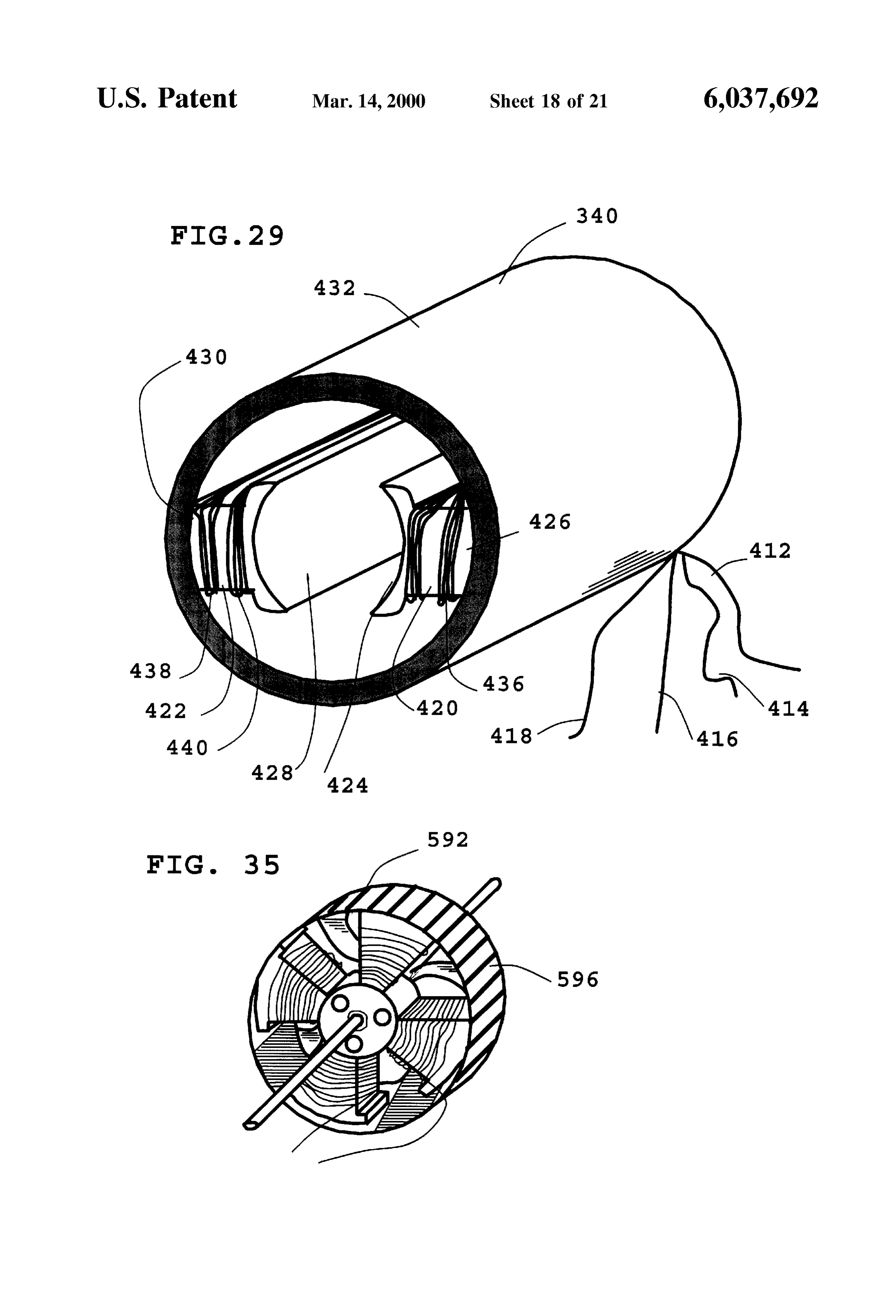
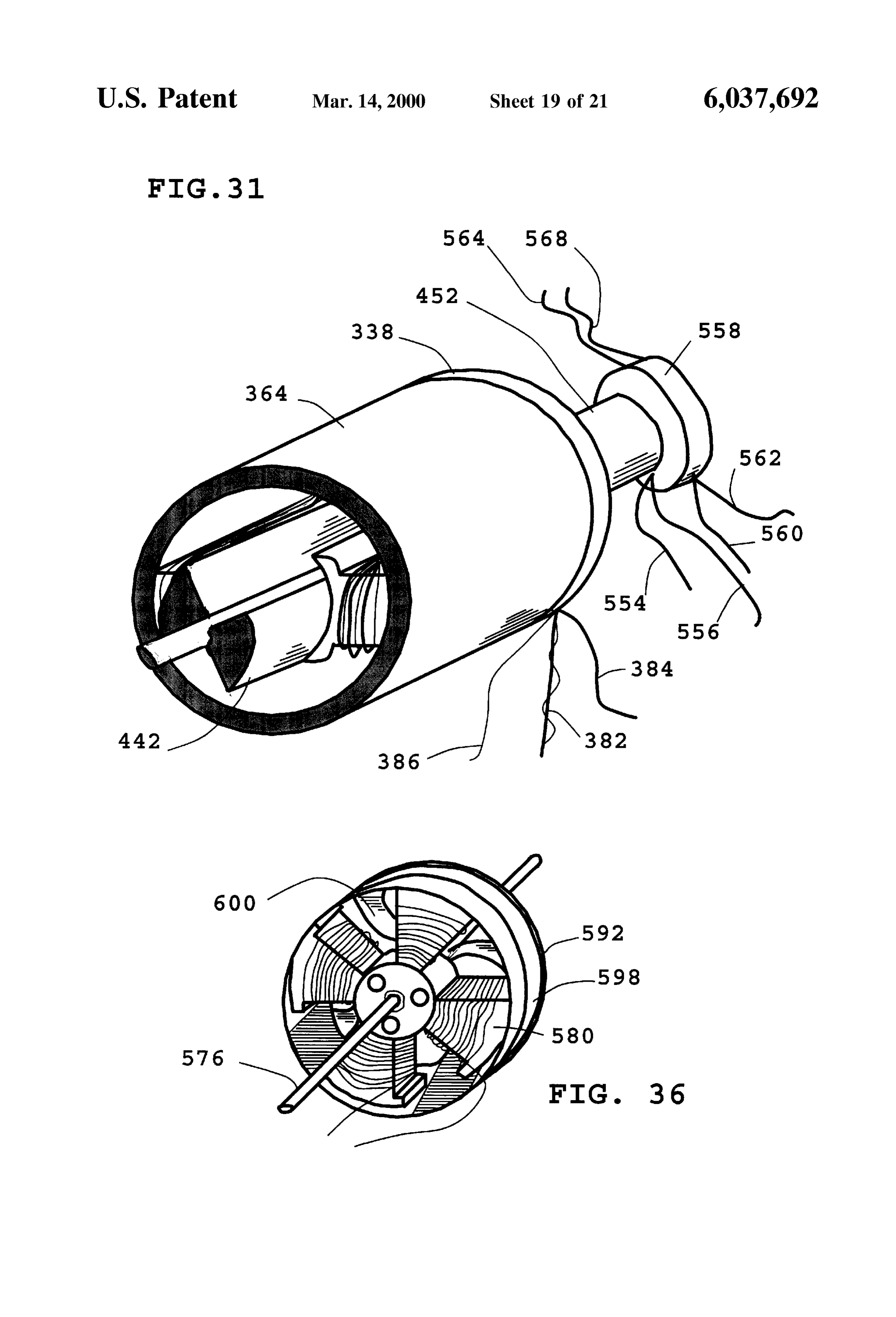
of a typical brushleSS D.C. permanent magnet electric motor FIG. 33 shows a large diameter brushless D.C. electric employing two isolated Sets of electromagnet windings on motor 592, consisting of the rotary portion of FIG. 32, and Stator electromagnets 420 and 422. Electromagnet casing a centrally located Star shaped electromagnet 580. Bearing 340 is made of steel and therefore is capable of efficiently 15 588 rotatably connects end plate 586 to motor shaft. End transmitting magnetic flux. Stator electromagnets 420 and plate 586 is fixedly 422 consist of laminated electrical Steel to reduce eddy shaped electromagnetmounted 580.
into the central portion of star
Mounting holes 590 are used to current losses when the motor is in operation. Stator elec mount the motor to a Suitable piece of equipment tromagnet 420 has two pole faces 424, and 426. Pole face frame of an automobile, or Some piece of highSuch as the powered 426 is attached to motor casing 340. Electromagnet pole face industrial equipment. Power input leads 582 and 584 pro 424 faces inward in a radial direction and is aligned with the vide power to star shaped electromagnet 580 through a opposing inward facing electromagnet pole face 428 of transistor amplification circuit (not shown) Such as the one electromagnet 422. Electromagnet 422 has a Second pole illustrated in FIG. 17 in the original patent application. The face 430 which is attached to motor casing 340. Both motor is timed with position sensing circuitry (not shown) electromagnets are wound with two Separate Sets of wind 25 such as the photocell gate assembly outlined in FIG. 15 in ings. Electromagnet 420 is wound with a first set of wind the original patent application.
ingS 434, and a Second Set of windingS 436. Electromagnet 422 is wound with a first set of electromagnet windings 438, FIG. 34 shows a large diameter brushless D.C. electric and a second set 440. Electromagnet windings 434, and 438 motor 592 having a rotary portion consisting of a central are connected together in Series and end at leads 412, and turbofan centrally and permanent magnets around the periphery, a located Star shaped electromagnet, and added gear 414. Electromagnet windings 436, and 440 are connected together in Series and end at leads 416, and 418. Applying teeth 594 around the outside periphery. electric power to either Set of leads results in a magnetic field FIG. 35 shows a large diameter brushless D.C. electric in electromagnets 420, and 422 that will not be sufficient to motor 592 having a rotary portion consisting of a central demagnetize rotor permanent magnets (not shown) under 35 turbofan and permanent magnets around the periphery, a motor stall conditions. When it is desirable to increase the centrally located Star shaped electromagnet, and teeth 596 field strength of electromagnets 420, and 422 power is for engagement to a cog belt around the outside periphery. appropriately applied to both Sets of leads. FIG. 36 shows a large diameter air cooled electric motor FIG. 30 shows the rotary portion of a typical D.C. 592 of this invention employed in a vehicle hub drive system brushless electric motor. Rotary portion 442 consists of a 40 having a Steel rim 598, permanent magnets attached to the shaft 322 attached to permanent magnets 444, and 446. inside portion, a Star shaped electromagnet assembly 580, Permanent magnets 444, and 446 have their direction of which is bolted onto the vehicle frame (not shown), and magnetization Such that exposed face 448 of permanent large Structural air moving Spokes 600 for connecting the magnet 446 is north and points outward in a radial direction, outer rim portion 598 to axle assembly 576. and exposed face 450 of permanent magnet 444 is south and 45 FIG. 37 shows the rotary portion 602 of a large diameter points outward in a radial direction as well. brushless D.C. motor consisting of a planar disc 604 having FIG. 31 shows a brushless D.C. electric motor of this permanent magnets 606 about the periphery in a radial invention having the front end cap removed to expose the direction, and fixed air moving vanes 608 protruding from inner workings. Rotor 442 of FIG. 30 is shown inside of the edge. In this particular large diameter rotor, permanent multi-tap electromagnet assembly 364 of FIG. 27. Also 50 magnets 606 have a direction of magnetization which is in shown is end cap 338 and small electric generator 452. a radial direction with each Successive permanent magnet Small electric generator puts out a Voltage which is propor being oppositely polarized. Fixed air moving vanes 608 are tional to motor RPM values and is used as part of the on the top surface of planar disc 604 and move air from top interlocking circuitry of this invention. Power output leads to bottom of the electromagnets (not shown). 554, and 556 of Small electric generator 452 are wired to a 55 FIG. 38 shows a large diameter brushless motor 610 relay such as relay 200 of FIG.20 in the original application. consisting of a planar disc rotor 602 having permanent Also shown is the photocell gate casing 558 which houses magnets 606 about the periphery in a radial direction, the photocell gate circuitry for Sensing rotor position. A electromagnets 614 pointing inward toward the edge of the detailed diagram of the photocell gate and light control disc disc, and fixed air moving vanes 608 protruding from the are shown in FIG. 15 of the original application. Photocell 60 edge of the disc which move air over electromagnets 614. gate sensor leads 560, 562, 564, and 568 are wired to the Also included is electromagnet mounting plate 616 along transistor amplification circuitry shown in FIG. 17 of the with bearings 618 and 620 which rotatably connect mount original application. Also wired to this circuitry of course are ing brackets 622, and 624 to motor shaft 626. Mounting motor power input leads 382, 384, and 386. brackets 622, and 624 are firmly fastened to mounting plate FIG. 32 shows the rotary portion 570, of a large diameter 65 616. Electric power is applied to leads 628, and 630 from the brushleSS D.C. electric motor consisting of a central turbofan transistor amplification circuit of FIG. 17 in the original portion 572, and permanent magnets 574 around the inside patent application (not shown). AS usual, Timing is provided
Page 34
by the photo-optic position Sensing apparatus of FIG. 15 in a commutator attached to Said shaft, and the original application (not shown). a Set of brushes attached to Said housing for applying FIG. 39 shows the rotary portion 630 of a large diameter electric power to Said electromagnets to cause Said brushleSS D.C. electric motor consisting of a central turbofan shaft to rotate.
portion 632, motor shaft 634, and non-magnetizable high 2. A motor claimed in claim 1 wherein Said electrical permeability material 638 mounted to inside surface 636 in interlocking circuitry is included as part of Said motor. the periphery portion of rotary portion 630 as well as 3. A motor as claimed in claim 1 further comprising a mounting hardware 686, 688, and 690 of FIG. 33. Also plurality of Said commutators and a plurality of Said Sets of employed is electromagnet 580 which is shown in FIG. 33. brushes.
Electromagnet timing is carried out using the photocell gate 4. A motor as claimed in claim 1 wherein Said electrical shown in FIG. 15 of the original patent application. Ampli fication of the timing Signal from the photocell gate is interlocking circuitry includes a centrifugal Switch. carried out using the electrical circuitry shown in FIG. 17 of 5. A motor claimed as in claim 1 wherein Said windings the original patent application. are electrically isolated from each other. FIG. 40 shows the rotary portion 640 of a large diameter 15 6. A motor as claimed in claim 1 wherein each Said brushleSS D.C. electric motor consisting of a planar disc 642 winding includes a first layer of electromagnet wire con having non-magnetizable high permeability material 644 nected to a first motor tap and a Second layer of electro embedded on the outside periphery, along with added air magnetic wire connected to a Second motor tap, Said wire of moving Surfaces 608. Also employed are electromagnets Said first layer having a thickness greater than Said wire of 614 of FIG.38, as well as mounting hardware 616, 618, 620, Said Second layer.
622, 624, and 626 of FIG. 38. As usual, electromagnet 7. AbrushleSS permanent magnet electric motor compris timing is carried out using the photocell gate shown in FIG. ing:
15 of the original patent application. Amplification of the a rotatable portion including: timing Signal from the photocell gate is carried out using the a shaft; and electrical circuitry shown in FIG. 17 of the original patent a plurality of permanent magnets each attached to Said application. 25
Those skilled in the art will understand that the embodi shaft and having a direction of magnetization and ments of the present invention described above exemplify poles, the present invention and do not limit the Scope of the Said poles of Said permanent magnets facing outward in invention to these specifically illustrated and described a radial direction and alternating with each Succes embodiments. The scope of the invention is determined by Sive of Said permanent magnets, the terms of the appended claims and their legal equivalents, a Stationary portion including: rather than by the described examples. In addition, the a housing for rotatably Supporting Said shaft and having exemplary embodiments provide a foundation from which an inner Surface, and numerous alternatives and modifications may be made, a plurality of electromagnets each attached to Said inner which alternatives and modifications are also within the 35
Scope of the present invention as defined in the appended Surface, having a direction of magnetization and claims. poles when electrically energized, and including a What is claimed is: winding, 1. A brush timed permanent magnet electric motor, com Said poles of Said electromagnets facing inward in a prising: radial direction and alternating with each Successive a Stationary portion including: 40 of Said electromagnets, and a housing having an inner Surface and end caps, and Said winding of at least one of Said electromagnets a plurality of permanent magnets each being disposed having a configuration that demagnetizes Said per on Said inner Surface of Said housing and having a manent magnets at Stall conditions, direction of magnetization and poles, 45 an electrical interlocking circuitry for allowing Said con
Said poles of Said permanent magnets facing inward in a figuration of Said winding of Said at least one of Said radial direction and alternating with each Successive of electromagnets to be activated when Said Shaft reaches Said permanent magnets, a preset Speed that reduces current in Said windings to a rotatable portion including: a level Sufficient to prevent demagnetization of Said a shaft rotatably attached to Said end caps of Said 50 permanent magnets, and housing, and a plurality of Shaft position Sensors with a Second elec a plurality of electromagnets each being attached to trical circuitry for properly timing and Switching elec Said Shaft, having a direction of magnetization and trical power into Said electromagnets, thereby causing poles, and including a winding capable of conductive Said shaft to rotate.
8. A motor as claimed in claim 7 wherein said electrical
Said poles of Said electromagnets facing outward in Said interlocking circuitry is fixedly attached to Said motor. 9. A motor as claimed in claim 7 wherein each said radial direction and alternating with each Successive of Said electromagnets, and winding includes two or more twisted wire Strands. 10. A motor as claimed in claim 7 wherein each said
Said winding of at least one of Said electromagnets having winding a configuration that demagnetizes Said permanent mag 60 nected toincludes a first a first layer of electromagnet wire con motor tap and a Second layer of electro nets at Stall conditions, magnetic wire connected to a Second motor tap, Said wire of an electrical interlocking circuitry for allowing Said con Said first layer having a thickness greater than Said wire of figuration of Said winding of Said at least one of Said Said Second layer.
electromagnets to be activated when Said Shaft reaches 11. A motor as claimed in claim 7 wherein Said windings a preset Speed that reduces current in Said windings to 65 are electrically isolated from each other. a level Sufficient to prevent demagnetization of Said permanent magnets, k k k k k
Provenance
- Collection
- Cited prior art
- Original PDF
- patentimages.storage.googleapis.com →
- Filed
- 1998-06-01
- Pages
- 34
- Method
- pdftotext (the PDF's own text layer) + pdftoppm 300dpi page scans
- Source
- Google Patents bibliographic record
- Granted
- 2000-03-14
- Inventors
- Fred N. Miekka; Peter W. Mackie
- Transcribed from
- patentimages.storage.googleapis.com →