patent · US2040218
Turbine gland
12 May 1936
Page 1
Drawing sheet — no readable text.
Page 2
Patented May 12, 1936
UNITED STATES PATENT OFFICE
TURBINE GLAND
Carl R. Soderberg, Swarthmore, Pa., assignor to
Westinghouse Electric & Manufacturing Com pany, East Pittsburgh, Pa., a corporation of
Pennsylvania
Application April 20, 1934, Serial No. 721,532
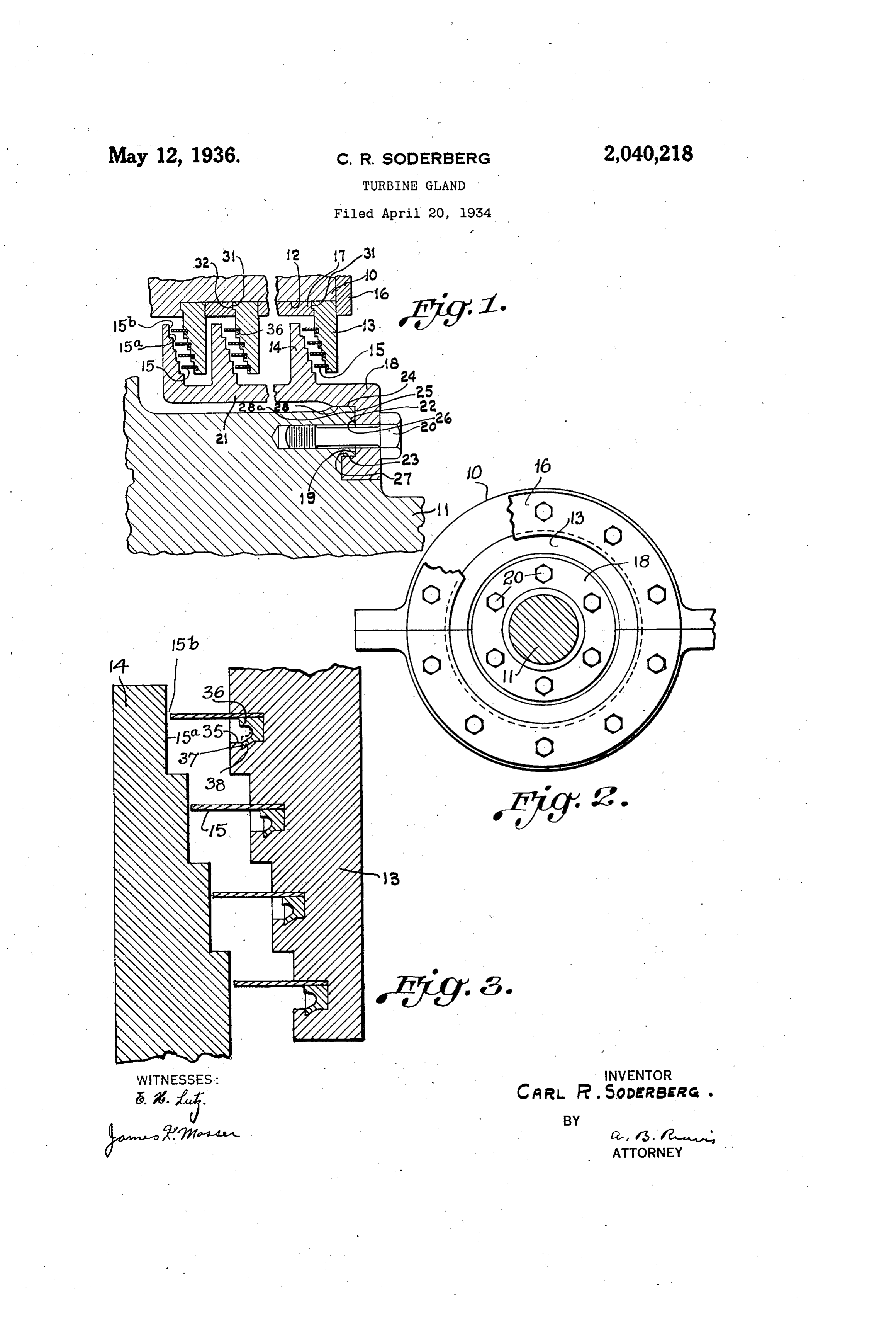
My invention relates to turbine glands of the description and claims taken in connection with radial labyrinth type and it has for an object tothe accompanying drawing, forming a part of provide apparatus of this character wherein the this application, in Which: Component parts may be assembled Without Fig. 1 is a sectional detail view of my improved shrinking On of any of the parts. gland; 5 A further object of my invention is to provide Fig. 2 is an end elevation of apparatus shown labyrinth packing comprised by overlapping col in Fig. 1; and lar elements provided with removable and axially Fig. 3 is a detail view drawn to an enlarged extending sealing or Wearing strips carried by Scale showing how the Sealing strips are con 0 the stationary collar elements and which define nected to the fixed collars. 0 Sealing clearances with respect to the rotatable In the drawing, the turbine housing and the collar elements. Spindle are respectively indicated at 0 and f, A further object of my invention is to provide a labyrinth packing consisting of a series of the axial housing having a cylindrical socket 2 co with the spindle.
5 radial labyrinth groups wherein the spindle-car The socket f2 has disposed therein a plurality 5 ried portions of the groups are provided by col of axially-spaced pairs of cooperating fixed and lars integral with a sleeve connected to the rotatable collars 3 and 4, each of the fixed Spindle and COOperating with stationary collars collars having coaxial circular metallic sealing having circumferential sealing or Wearing strips, Strips 5 extending laterally from One face there 20 both the stationary collars and the strips being Of and COOperating With the adjacent rotatable
made in arcuate or semi-circular sections to per collar 4.
mit of assembly and dismantling of the packing. The fixed collars 3 are shown confined in the A further object of my invention is to provide socket 2 by the clamping ring 16, the collars a labyrinth packing characterized by a large being maintained in Spaced relation by the spac 25 number of throttlings in a given space.
ing collars 7; however, it is to be understood 25
A further object of my invention is to provide that a gland of the labyrinth type consisting of a in any the collars 3 may be secured to the stator Suitable manner.
series of radial labyrinth groups wherein the ro A ring 8 is attached to the spindle by the tary parts are provided by axially-spaced col annular tongue-and-groove connection 9 and by 30 lars integral with a sleeve, the sleeve being spaced the Screws or bolts 20, the ring having an in
from the spindle except for the outer end portion Wardly-extending sleeve portion 2, which is thereof, and the outer end portion constituting Spaced from the spindle. The rotatable collars a part of the connecting means with the spindle, f4 are integral with the sleeve portion 2 . whereby the major portion of the sleeve and the The annular tongue-and-groove connection 9 35 collars is free to expand without restraint by includes a tongue 22 provided on the spindle and 35 the rotor body in case of heat being generated having inner and Outer coaxial cylindrical Sur by any rubbing of the packing elements, thus faces 23 and 24 and an end surface 25, which relieving the points where rubbing occurs, is normal to the spindle axis. The ring 8 has A further object of my invention is to provide a groove 26 provided with inner and outer cylin a gland between a turbine spindle and its hous drical Surfaces 27 and 28 and a bottom surface 28a. 40 ing consisting of a series of axially-aligned radial which accurately fit the tongue surfaces 23, 24, labyrinth groups each consisting of radially and 25, respectively, whereby it is assured that, Overlapping fixed and rotatable collars, with the When the ring is in place, the sleeve portion 2 rotatable collars integral with a sleeve connected 45 at its Outer end to the Spindle and with the Will be accurately centered and retained in place With respect to the spindle axis. 45 stationary collars carried by the housing and As shown in Fig. 2, each of the fixed collars 3, made in Semi-circular parts to permit assembly as Well as the Sealing strips 5 carried thereby, and dismantling, the circular and coaxial sealing are Split or made in Semi-circular sections to pro Strips being formed by registering Semi-circular vide for assembly and dismantling of the appara 50 parts carried by the semi-circular parts of the tuS. The Semi-circular sections of the collars. 3 50 stationary collars and being readily mounted on are provided with semi-circular lateral tongues 3 and removable from the Semi-circular parts SO at their Outer edges, the tongues being arranged to as to permit of their replacement. tfit in grooves 32 formed in the end wall of the These and other objects are effected by my in socket and in the spacing rings 7, whereby it is 55 vention as will be apparent from the following assured that, when assembled, the component 55
Page 3
parts of the fixed collars will be accurately held with a choice of suitable material, provide for in circular formation with the ends of the Seal Wear in case of rubbing So that very fine running ing strips in circumferential alignment. clearances may be provided. The strips may be As will appear from FigS. 2 and 3, each semi readily Secured in position and removed particu circular fixed collar half or section is provided larly, as the fixed collars are made in semi-circu with similar arcuate grooves 35 within Which are lar sections, whereby strips may be readily placed disposed the semi-circular Sealing strip sections, in grooves of complementary collar parts and each sealing strip section being clamped against caulked with the adjacent ends finished or trued one wall of a groove 35 by a deformable caulking SO as to a line and fit closely together in order 10 strip 36 fitting between the latter and the other to aggregate a cylindrical Sealing strip. Further 10 wall of the groove, said other wall of the groove more, by having the fixed collars made up of com preferably being recessed to provide an in Wardly plementary parts, each carrying complementary facing arcuate shoulder 37 and the deformable parts of the Sealing strips, the ends of the caulk strip having a tongue 38 which may be rolled or ing are exposed so that they may be readily pried 15 pressed behind the shoulder so as to clamp the up incident to removal thereof when taking out 15 sealing strip firmly in place. The caulking strip a Sealing Strip. Also, as the rotatable collars are before deformation is indicated by dot and dash carried by a sleeve spaced from the spindle, a lines at the upper portion of Fig. 3. As the Walls Structure is provided which is self-relieving in of grooves 35 engaged by the Sealing strips 30 case of rubbing.
20 are cylindrical surface elements coaxial With the While I have shown my invention in but one 20 spindle axis, it will be apparent that bending of form, it will be obvious to those skilled in the art the strips incident to caulking thereof against that it is not so limited, but is susceptible of said groove walls results in cylindrical sealing Various changes and modifications without de strips carried by the fixed collars and extending parting from the spirit thereof, and I desire, 25 toward and defining sealing clearances with re therefore, that only such limitations shall be spect-to the rotatable collars. If it is desired to placed thereupon as are imposed by the prior replace the sealing strips in case of Wear or for art or as are specifically set forth in the appended any other reason, this may be readily done, for, claims.
by having the fixed collars made in Sections, the What I claim is:
30 ends of the deformable strips are accessible to be 1. In a gland for Sealing a turbine spindle with 30 pried out at the ends of the grooves, whereupon respect to its housing including cooperating and such pried-out ends may be engaged by a tool axially-Spaced pairs of radially-overlapping ro of the key type, the tool being turned and the tatable and fixed collars, the fixed collars being deformed packing strip being Wrapped there Carried by the housing and the rotatable collars 35 about, the tongue 38 being sheared off by the having radially extending sealing faces, a plural 35 shoulder. Upon removal of a sealing strip, a new ity of coaxial and thin metallic strips extending sealing strip and deformable packing may be in laterally from One side of each fixed collar and serted. defining radially extending Sealing clearances As will be apparent from Fig. 1, each stationary With respect to the radially-extending sealing 40 4) collar 3 has a group of axially-extending strips faces of the adjacent rotatable collars, means for 5 whose free edges cooperate with radially-ex Connecting the Strips to the fixed collars, each of tending sealing faces. 5a on the cooperating Said fixed collars and the strips carried thereby moving collar 4. The strips of each group pref being comprised by registering semi-circular sec erably radially overlap so that the radial clear tions, a sleeve integral with the rotatable collars 45 45 ances 5b are progressively offset, whereby there and overhanging the Spindle in spaced relation is provided a devious flow path for leakage except for the Outer end portion thereof, and medium and the resistance to flow is consequently means for connecting the outer end portion of increased. As the strips 5 are made of thin the sleeve to the Spindle.
metal, they areradially wearable in case of rub 2. In a gland for sealing a turbine spindle with 50 50 bing. Furthermore, with strips made of thin respect to its housing including cooperating and metal, preforming of the strips is unnecessary, as axially-Spaced pairs of radially-overlapping ro the cylindrical formation is assumed incident to tatable and fixed collars, the fixed collars being assembly. From the foregoing, it will be apparent carried by the housing and the rotatable collars that I have provided a spindle and a housing having radially-extending Sealing faces, a plural 55 Which are separated to provide an annular space ity of coaxial and thin metallic Strips extending 55 together with rotatable and fixed overlapping col laterally from one side of each fixed collar and lars extending radially into said space and car defining radially-extending Sealing clearances ried, respectively, by the spindle and by the with respect to the radially-extending faces of housing. The housing includes complementary the adjacent rotatable collar, means for connect 60 60 parts, and, for this reason as well as to permit assembly of the housing parts With the fixed Col ing the strips to the fixed collars, a sleeve integral lars extending into the spaces between adjacent With the rotatable collars and overhanging the spindle in Spaced relation except for the outer rotatable collars the fixed collars are also made in complementary parts carried by the housing end portion thereof, said spindle having an an 65 parts. The housing is provided with an interior nular tongue defined by cylindrical Surfaces co 65 cylindrical socket including complementary por axial with the Spindle axis and by a Surface nor mal to said cylindrical surfaces and Said outer tions in the complementary housing parts, and end portion of the sleeve having a groove defined the outer margins of the fixed collar parts are fastened in the complementary Socket portions. by cylindrical Surfaces and a bottom. Surface ac 70 As the sealing strips are carried by the fixed Col curately fitting said tongue Surfaces and the 70 lars, they are free of centrifugal effects and may cylindrical surfaces of the groove being coaxial be made relatively wide and thin. Furthermore, With its axis and the bottom Surface thereof being thinness of the strips gives the requisite flexibility normal to said axis, and ScreWS for holding the facilitating assembly and cylindrical conforma sleeve and the spindle together. 3. In a gland for sealing a Spindle with respect 75 tion thereof when assembled; and thinneSS, taken
Page 4
to its housing, a plurality of pairs of radially including complementary portions provided in Overlapping rotatable and fixed collars, the fixed the respective complementary fixed collar collars being carried by the housing and the ro parts, a cylindrical Sealing Strip element in tatable collars having radial sealing faces, a each groove conforming to and Seated against the group of coaxial Sealing strips COOperating With cylindrical Wall thereof and COOperating With 5 the Sealing faces of each rotatable collar to define the adjacent side of the rotatable collar to define a plurality of radially-extending sealing clear Sealing clearance, each sealing strip element in ances, means providing for attachment of the cluding complementary parts of relatively thin groups of strips to the respective stationary col and flexible metallic strip material arranged in 0 lars, a sleeve integral with the rotatable collars the respective complementary portions of each 10 and overhanging the spindle in spaced relation groove, and caulking in each groove portion and With respect to the latter except for the Outer engaging the associated Strip part to grip the lat end portion thereof, and means for connecting ter in place with respect to the cylindrical Wall the outer end portion of the sleeve directly to of the groove portion, the ends of the comple 15 the spindle. mentary arcuate portions of a Sealing strip ele 4. In combination. With a housing having a ment and its caulking being contiguous When 15 cylindrical socket, a spindle coaxial with the the parts of a fixed collar are brought together in Socket, a plurality of axially spaced and radially aSSembled relation.
Overlapping rotatable and fixed collars, said ro 6. The combination with a housing having 20 tatable collars having radially-extending Sealing complementary parts providing an interior axial 20 faces, coaxial and circular thin metallic strips ly-extending opening and a spindle extending extending from one face of each of said fixed col through said opening and separated from the Wall lars and cooperating with the radially extending of the latter by an annular Space, of one or more sealing faces of the adjacent rotatable collar to Cooperating pairs of radially Overlapping fixed 25 define radially-extending Sealing clearances, and rotatable collars extending into said annular 25 means for connecting the strips to the fixed col Space and carried by the housing and by the lars, each of said fixed collars and the metallic spindle, respectively, each fixed collar including strips carried thereby being comprised by Com complementary parts carried by the respective plementary arcuate sections, means for confining complementary parts of the housing and each 30 the sectional fixed collars in axially spaced rela fixed collar having one or more circular lateral 30 tion in said socket, a sleeve integral with the ro grooves therein at a single side thereof and the tatable collars and spaced from the spindle ex grooves being on like sides of the fixed collars, cept for the outer end portion thereof, and means each groove having a wall which is cylindrical for connecting the other end portion of the sleeve and coaxial with the Spindle axis and each groove 35 to the spindle and providing for centering of the including complementary portions provided in 35 sleeve with respect to the latter. the respective complementary fixed collar parts, 5. The combination with a housing having a cylindrical sealing strip element in each groove complementary parts providing an interior axial conforming to and seated against the cylindrical ly-extending opening and a spindle extending wall thereof and cooperating with the adjacent 40 through said opening and separated from the Wall side of the cooperating rotating collar to define 40 of the latter by an annular space, of a cooperat Sealing clearance, each sealing strip element in ing pair of radially Overlapping fixed and ro cluding complementary parts of relatively thin tatable collars extending into said annular space and flexible metallic strip material arranged in and carried by the housing and by the spindle, the respective complementary portions of each 45 respectively, said fixed collar including comple groove, and caulking in each groove portion and mentary parts carried by the respective comple engaging the associated strip part to grip the mental parts of the housing and said fixed col latter in place with respect to the cylindrical Wall lar having one or more circular grooves formed of the groove portion.
in a single side thereof, each circular groove hav 50 ing a wall which is cylindrical and each groove CAR. R. SODERBERG. 50
Provenance
- Collection
- Cited prior art
- Original PDF
- patentimages.storage.googleapis.com →
- Filed
- 1934-04-20
- Pages
- 4
- Method
- pdftotext (the PDF's own text layer) + pdftoppm 300dpi page scans
- Source
- Google Patents bibliographic record
- Granted
- 1936-05-12
- Inventors
- Carl R Soderberg; Westinghouse Electric Corp
- Transcribed from
- patentimages.storage.googleapis.com →