patent · US4521026
Shaft seal
4 June 1985
Page 1 — bibliographic record
United States Patent (19) 11) Patent Number: 4,521,026 Eide (45) Date of Patent: Jun. 4, 1985 54 SHAFT SEAL Primary Examiner-Robert I. Smith 75) Inventor: Daniel L. Eide, Carmel, Ind. Attorney, Agent, or Firm-Birgit E. Morris; Donald S. Cohen 73) Assignee: RCA Corporation, Princeton, N.J. (57) ABSTRACT 21 Appl. No.: 534,386 A packingless shaft seal between an apparatus housing 22) Filed: Sep. 21, 1983 and a rotatable shaft. The shaft seal includes a sleeve 51) Int. Cl. ............................................... F16J 15/34 mounted on the shaft and a seal housing mounted on the 52 U.S. Cl. ....................................... 277/134; 277/16 apparatus housing and around the sleeve. The sleeve 58) Field of Search .................................. 277/134, 16 has a variable pitch thread extending from its ends within the apparatus housing to the seal housing and a 56) References Cited cylindrical portion within and spaced from the inner
directed toward the interior of the apparatus housing so 450,004 4/1891 Daley . that upon rotation of the shaft, material entering the 2, 182,981 2/1939 Drost et al. ............................. 286/5 thread is moved back into the apparatus housing. The 2,383,531 8/1945 Caruthers ...... ... 286/5 seal housing has a chamber therein through which a 2,713,927 7/1955 Rabinow ... ... 192/21.5 2,818,284 12/1957 Stevens ................................. 277/16 temperature control material flows to control the ten 2,865,615 12/1958 Slaughter ...... ... 277/16 perature of the material passing between the seal hous 3,004,782 10/1961 Meermans ..... ... 286/5 ing and the sleeve.
3,071,384 1/1963 Friberg ......... ... 277/3 3,700,247 10/1972. Butler et al. ........................ 277/134 6 Claims, 1 Drawing Figure
zzz 2X2ZZZZZZZL
NSN
Page 2
Drawing sheet — no readable text.
Page 3
between the inlet opening and the back end of the hous
SHAFT SEAL ing to prevent plastic material entering the inlet opening 20 from passing out of the back end of the housing 12.
BACKGROUND OF THE INVENTION The shaft seal 24 includes a cylindrical sleeve 26 The present invention relates to a shaft seal, and more surrounding and secured to the shaft 16 and a seal hous particularly to a packingless shaft seal. ing 28 surrounding the sleeve 26 and secured to the In preparing a thermoplastic material for use in com housing 12 at the back end thereof. The sleeve 26 ex pression or injection molding, the ingredients of the tends from adjacent the inlet opening 20 along the cylin plastic material are generally mixed together and then drical surface 22 and the seal housing 28 to a point passed through an extruder to pelletize the plastic mate 10 beyond the seal housing 28 and beyond the back end of rial. The extruder generally includes a shaft having a the housing 12. The sleeve 26 has an internally threaded screw thread in its outer surface and rotatably Sup portion 30 at its forward end which is threaded on the ported in a housing. The thermoplastic material is fed to shaft 16 so that the sleeve will rotate and reciprocate the shaft at the rear end of the screw thread and is with the shaft 16. The outer diameter of the sleeve 26 is forced along the screw thread to a pelletizing mecha slightly less than the inner diameter of the cylindrical nism at the front end of the shaft. The rear end of the surface portion 22 so that there is a slight clearance, shaft is generally supported in a bearing having a seal between about 0.003 inches and 0.022 inch, between the which prevents the thermoplastic material from flowing cylindrical surface portion 22 and the sleeve 26 depend rearwardly along the shaft. The shaft seal generally includes some type of packing material around the shaft. 20 ing on the material being treated. The sleeve 26 has an . external, variable pitch thread 32 extending from its
However, when extruding certain types of thermoplas front end to a point just within the seal housing 28. The tic material, it was found that the extruded plastic mate thread 32 varies from a wide pitch, about 2 inches, at the rial contained contaminating particles which were front end of the sleeve 26, to a finer pitch, about 0.5 pieces of the packing material. Therefore, for extruding inch, this type of thermoplastic material, it was found desir- 25 threadat32theis point just within the seal housing 28. The directed inwardly toward the inside of the able to have an extruder which includes a packingless housing 12 so that when the sleeve 26 is rotating with shaft seal which would not contaminate the plastic ma the shaft 16, any plastic which terial but which would provide the desired sealing ac be pushed back to the inside ofenters the thread 32 will the housing 12.
tion.
The seal housing 28 is formed of a cylindrical bushing
SUMMARY OF THE INVENTION 3O 34 which has an internal diameter equal to the internal An apparatus includes a housing, a shaft rotatably diameter ofradially the cylindrical surface 22 and a flange 36 supported in a bearing in the housing and a seal between extending inner surface of the outwardly from its inner end. The bushing 34 has therein a plurality of the shaft and surface of the housing preventing the flow of material from the interior of the housing along the 35 circumferentially grooves 37 which spaced, longitudinally extending extend from the outer end thereof to shaft. The seal includes a sleeve surrounding and se cured to the shaft to rotate therewith. The sleeve ex substantially the flange 36. An outer ring 38 extends tends along the surface of the housing and has in its around the bushing 34 and is secured to the flange 36 by outer surface a variable pitch thread with the threads screws 40. The ring 38 has a recess 42 in its inner sur being directed towards the interior of the housing so as 40 face. An annular cover 44 extends around the bushing to direct any material entering the thread back into the 34 and is secured to the ring 38 by screws 46. The cover housing upon rotation of the shaft. 44 extends across the end of the recess 42 so that the recess 42 forms with the cover 44 and bushing 34 an
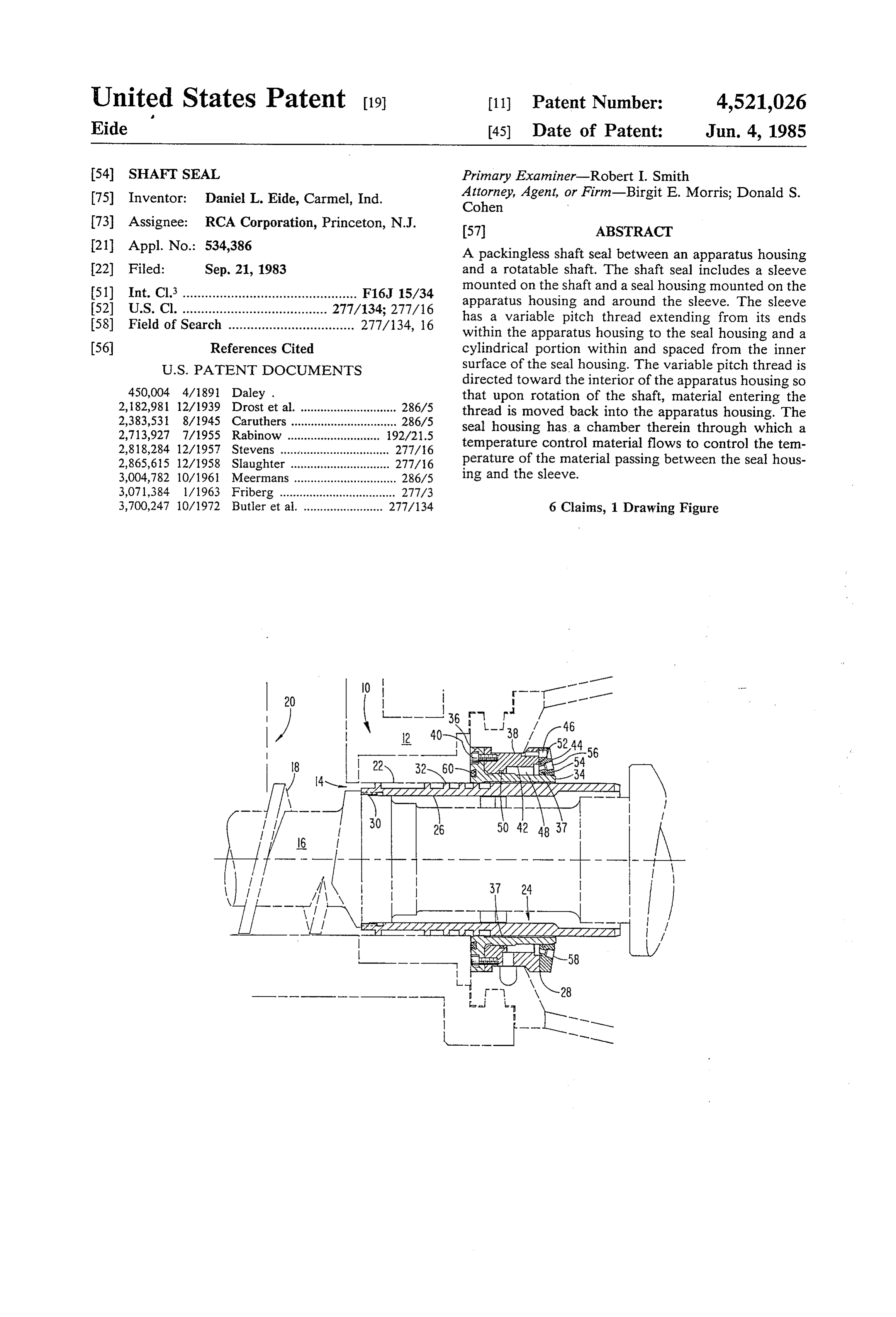
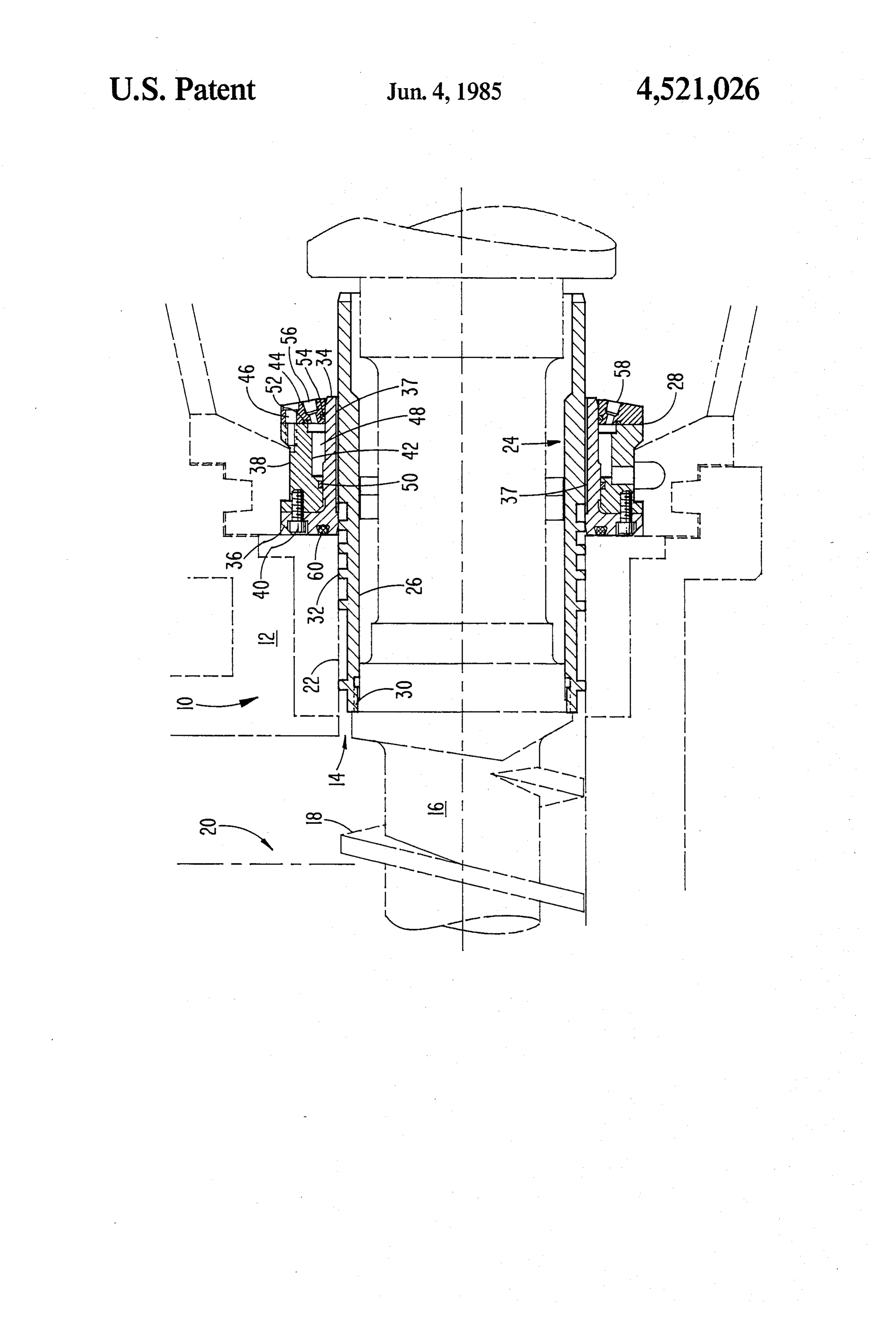
BRIEF DESCRIPTION OF THE DRAWING enclosed chamber 48. A sealing ring 50 is provided The FIGURE of the drawing is a sectional view of a 45 between the outer ring 38 and the bushing 34 at one end portion of an extruder which includes the shaft seal of of the chamber 48, and at the other end of the chamber, the present invention. sealing rings 52 and 54 are provided between the cover
DETAILED DESCRIPTION OF PREFERRED
44 and the outer ring 38 and bushing 34 respectively.
EMBODIMENT
Inlet and outlet openings 56 and 58 extend through the 50 cover 44 to the chamber 48 through which a flow of a
Referring to the drawing, a plastic extruding appara heat control medium can be provided through the tus which incorporates the seal of the present invention chamber 48. A sealing ring 60 is provided between the is generally designated as 10. The extruding apparatus flange 36 and the adjacent surface of the housing 12. 10 includes a housing 12 having a passage 14 extending In the operation of the extruding apparatus 10, the longitudinally therethrough. Within the passage 14 is a 55 thermoplastic material in dry particulate form is fed shaft 16 which is supported in bearings (not shown) through the inlet opening 20 in the housing 12 to the which allow rotation of the shaft 16 with respect to the rotating shaft 16. Most of the plastic material is carried housing 12 as well as slight longitudinal movement of by the shaft threads 18 toward the front end of the the shaft with respect to the housing. The portion of the housing 12 to the pelletizing mechanism. However, shaft 16 within the housing 12 has an external thread 18 60 some of the plastic material will flow or be forced back which is adapted to move plastic material along the into the shaft seal 24. The plastic material that does shaft 16 from an inlet opening 20 at the back end of the enter the shaft seal 24 will flow through the clearance housing 12 to a pelletizing mechanism (not shown) at between the sleeve 26 and the cylindrical surface 22. the front end of the housing 12. The passage 14 has a Most of this plastic material will fall within the threads cylindrical surface portion 22 extending from the inlet 65 32 and will be forced by the rotation of the sleeve 26 opening 20 to the back end of the housing 12. The shaft back toward the inlet opening 20. However, because of seal of the present invention, generally designated as 24, the pressure of the material entering through the inlet is mounted along the shaft 16 and cylindrical surface 22 opening 20 a small portion of the plastic material enter
Page 4
ing the shaft seal 24 will flow along the sleeve 26 until interior of said housing, a shaft rotatably supported in it enters the clearance between the sleeve 26 and the said housing and extending through said passage, and a bushing 34. The plastic material that does enter the seal between said shaft and a surface of said passage for clearance between the sleeve 26 and the bushing 34 will limiting flow of the particulate material through said be worked by the relative rotation between the sleeve 5 passage along said shaft, the improvement comprising 26 and the bushing 34 as well as by the finer pitched the seal including a sleeve surrounding and secured to threads just prior to the bushing 34. This combined the shaft to rotate therewith, said sleeve extending working of the plastic material will cause it to heat up along said surface of the passage, and having in its and flux to a molten state. By controlling the viscosity outer surface a variable pitch thread with the of the plastic in the space between the sleeve 26 and O threads being directed toward the inlet opening bushing 34, the plastic material will act as a seal to within the housing so as to direct most of the par prevent the loss of plastic material but will still allow ticulate material entering the threads in a direction relative rotation between the shaft 16 and the housing back into the housing upon rotation of the shaft but 12. It has been found that good sealing action is ob allowing a small amount of material to flow along tained when the viscosity of the plastic material is such 15 the passage in a direction opposite to the interior of that a small extrusion of the plastic material is provided the housing:
from the back end of the shaft seal 24. The grooves 37 the sleeve having a cylindrical portion extending in the inner surface of the bushing 34 provide uniform along the surface of the passage from the threads to distribution of the fluxed material around the sleeve 26 the exterior of the housing and being slightly to provide good sealing even if there are slight eccen spaced from Said surface of the passage; and tricities in the rotation of the shaft. The viscosity of the heat control means surrounding and being remote plastic in the space between the sleeve 26 and bushing from said space between the cylindrical portion of 34 is controlled by a temperature control medium the sleeve and the surface of the passage to main flowed through the chamber 48. For a plastic material tain the small amount of material which flows into which is of polyvinylchloride filled with carbon parti 25 the space in a molten condition. cles, maintaining the plastic at a temperature of about 2. An apparatus in accordance with claim 1 in which 300 F. has been found to provide the plastic with a the heat controlling means includes a chamber in a viscosity suitable for forming a good seal. However, housing around said portion of the surface of the pas proper fluxing of the plastic material can be achieved by sage and means for allowing the flow of a heat control optimizing the clearance between the sleeve 26 and 30 medium through said chamber.
bushing 34 which would eliminate the need of a temper 3. An apparatus in accordance with claim 2 in which ature control medium. the housing containing the heat control chamber in Thus, there is provided by the shaft seal 24 of the cludes a bushing surrounding the sleeve and having a present invention an extruder in which there is no pack radially outwardly extending flange at one end, a ring ing material which can contaminate the material being 35 surrounding the bushing and secured to the flange, said sealed and in which the material being sealed forms its ring having a recess in its inner surface, and a cover own sealing action between the shaft and the housing. around the bushing and secured to the ring, said cover Although there is some loss of the plastic material extending across and enclosing the recess in the ring to through the shaft seal 24, the amount is very small and form the chamber.
does not interfere with the proper operation of the ap 4. An apparatus in accordance with claim 3 including paratus 10 being sealed. In addition, it has been found inlet and outlet passages extending through the cover that the time that any material which is forced back to into the chamber.
the screw thread 18 remains with the variable pitch 5. An apparatus in accordance with claim 1 in which thread 32 is sufficiently short that the material does not the pitch of the thread in the sleeve varies from a larger degrade. If this material were to degrade, it would con 45 pitch at its end within the housing to a finer pitch at the taminate the material passing through the extruder. cylindrical portion.
I claim: 6. An apparatus in accordance with claim 5 in which 1. In an apparatus which includes a housing having a the pitch of the thread in the sleeve varies from about passage extending from the exterior of the housing to an 0.5 inch at its end within the housing to about 2 inches inlet opening within the interior of the housing through at the cylindrical portion.
which dry particulate thermoplastic material enters the
Provenance
- Collection
- Cited prior art
- Original PDF
- patentimages.storage.googleapis.com →
- Filed
- 1983-09-21
- Pages
- 4
- Method
- pdftotext (the PDF's own text layer) + pdftoppm 300dpi page scans
- Source
- Google Patents bibliographic record
- Granted
- 1985-06-04
- Inventors
- Daniel L. Eide; RCA Corp
- Transcribed from
- patentimages.storage.googleapis.com →