patent · US5952755
Permanent magnet motor rotor
14 September 1999
Page 1 — bibliographic record
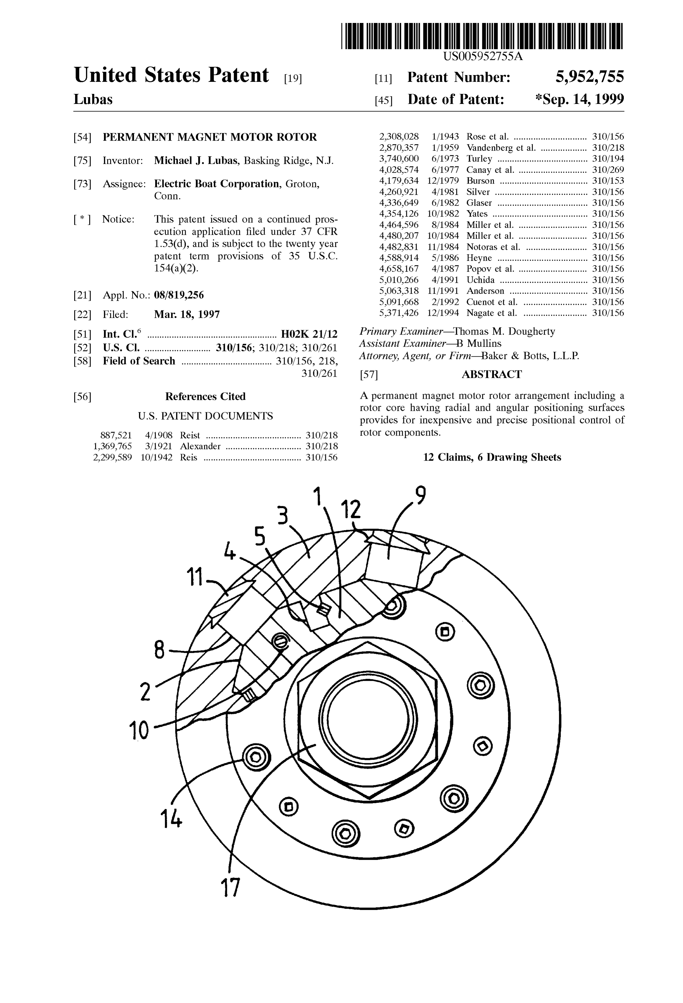
United States Patent (19) 11 Patent Number: 5,952,755 Lubas (45) Date of Patent: *Sep. 14, 1999 54 PERMANENT MAGNET MOTOR ROTOR 2,308,028 1/1943 Rose et al. .............................. 310/156 2,870,357 1/1959 Vandenberg et al. ................... 310/218 75 Inventor: Michael J. Lubas, Basking Ridge, N.J. 3,740,600 6/1973 Turley ..................................... 310/194 4,028,574 6/1977 Canay et al. 310/269 73 Assignee: Electric Boat Corporation, Groton, 4,179,634 12/1979 Burson - - - - - - - - - - - - - - - - - - - - - - - - - - - - - - - - - - - - 310/153 Conn. 4,260,921 4/1981 Silver ...................................... 310/156 4,336,649 6/1982 Glaser . ... 310/156 4,354,126 10/1982 Yates ....... ... 310/156 * Notice: This patent issued on a continued pros- 4,464,596 8/1984 Mille, et al. ............................ 310/156 ecution application filed under 37 CFR 4,480,207 10/1984 Miller et al. ............................ 310/156 1.53(d), and is subject to the twenty year 4,482,831 11/1984 Notoras et al. ......................... 310/156 patent term provisions of 35 U.S.C. 4.588.914 5/1986 Heyne ..................................... 310/156 154(a)(2). 4,658,167 4/1987 Popov et al. 310/156 5,010,266 4/1991 Uchida ........ ... 310/156 5,063,318 11/1991 Anderson ... ... 310/156 21 Appl. No.: 08/819,256 5,091,668 2/1992 Cuenot et al. .......................... 310/156 22 Filed: Mar 18, 1997 5,371,426 12/1994 Nagate et al. .......................... 310/156 51) Int. Cl.6 ..................................................... HO2K 21/12 Primary nary Examiner Thomas M. Doughert gnerly 52 U.S. Cl. ........................... 310/156; 310/218; 310,261 Assistant Examiner-B Mullins 58) Field of Search 310/156, 218 Attorney, Agent, or Firm-Baker & Botts, L.L.P.
56) References Cited A permanent magnet motor rotor arrangement including a rotor core having radial and angular positioning Surfaces
887,521 4/1908 Reist ....................................... 310/218 rotor components.
1,369,765 3/1921 Alexander ... ... 310/218 2,299,589 10/1942 Reis ........................................ 310/156 12 Claims, 6 Drawing Sheets
Page 2
Drawing sheet — no readable text.
Page 3
Drawing sheet — no readable text.
Page 4
Drawing sheet — no readable text.
Page 5
Drawing sheet — no readable text.
Page 6
Drawing sheet — no readable text.
Page 7
Drawing sheet — no readable text.
Page 8
PERMANENT MAGNET MOTOR ROTOR Susceptible to damage and/or demagnetization from over heating. Unfortunately, the magnets are directly exposed to
BACKGROUND OF THE INVENTION heat effects associated with air gap Surface losses, eddy This invention relates to a permanent magnet motor rotor current heating and heat associated with mechanical vibra arrangement which increases motor or generator efficiency nets near their from tions induced air gap harmonics. Heating these mag
Curie temperature can cause demagnetization and can withstand high impact shock loads and high cen and result in performance loSS. Moreover, shorts in Simple trifugal loads. The permanent magnet motor rotor provides turn-to-turn or phase-to-phase Stator windings may produce for inexpensive and precise positional control of rotor com dramatic heating of magnets installed in conventional rotors ponents. and thus lead to demagnetization. Conventionally the most commonly used integral horse Further, conventional permanent magnet rotors offer little power motor rotors have a Squirrel cage construction and are or no protection from magnet damage or demagnetization used in alternating current (AC) induction motors. AC and under Severe operating conditions or common motor and direct current (DC) generators typically include wound generator casualties. The magnets are Susceptible to physical rotors. DC motors usually include a commutator and rotor 15 damage because they are usually located on, or have at least windings. Each of these motorS or generators have rotors one Side totally exposed to the rotor air gap Surface. which differ Significantly from a rotor including permanent Accordingly, imposed Shock loads, high vibration levels or magnets. In addition, each of these rotorS develop a rotor mechanical failure of Some other closely aligned motor or magnetic field by electrical current flowing through the generator part can result in physical impact to the magnets rotor. As a result, all these rotors are excessively large, leSS thereby damaging the magnets.
efficient, more difficult to cool and of complex construction. Typically, permanent magnet rotors which utilize embed Heretofore, rotors including permanent magnets utilized ded magnets allow the pole pieces to bear directly onto the curved magnets which were fixed with adhesive to the magnets. Since the magnet material is brittle, this precludes periphery of the rotor. Other permanent motor rotors, typi the use of these magnets as reliable StreSS bearing Structural cally much Smaller in size, utilized magnets embedded in the 25 members in many applications, particularly where large Steel rotor core. In that case, Stacks of rotor laminations rotors are required. Moreover, permanent magnet rotors which form pole pieces are generally Secured to the rotor generally use only Single magnets to establish rotor poles. AS using threaded fastenerS or dovetails. Use of the dovetails or the size of a permanent magnet rotor increases, Single fasteners typically increaseS rotor cost and adds excessive magnet configurations are more Susceptible to physical parts to the rotor assembly. damage from bending, torsional and shear Stresses because, Unfortunately, precise location of rotor pole pieces in as previously discussed, these magnets are very brittle and permanent magnet motor and generator rotorS is difficult to do not contain the physical Strength associated with other achieve and as a result Such rotors are usually noisy. Such metallic rotor components.
precision is necessary when using the rotor for applications In addition, the Single magnets used to create poles in where torque fluctuations and cyclical radial loads must be 35 conventional permanent magnet rotorS may become difficult kept to a minimum. Moreover, the inability to provide and hazardous to handle as the rotor Size increases. precise radial position and angular orientation of rotor parts Typically, permanent magnet rotors utilize powerful rare can degrade overall rotor or generator performance, cause earth magnets that have Strong magnetic fields. Handling of unacceptable vibration levels and reduce efficiency. Such physically large magnets, each with a large magnet In addition, loosening of the rotor assembly can occur 40 field requires development of Special tooling and procedure during operation due to normal motor or generator Vibration. to handle the magnets. Working with large magnets in the Loosening of parts can degrade performance or even cause vicinity of Surrounding ferromagnetic material may also mechanical damage to motor or generator parts. Vibration pose Safety hazards to perSonnel.
may also loosen and cause failure of adhesive bond lines Further, the difficulties in manufacturing and magnetiza which can result in release of the permanent magnets 45 tion of large Size Single magnets limits the size and ratings installed on the motor rotor. Degraded performance or attainable in conventional pulse modulated motor and gen mechanical damage may result from magnets which are erator designs.
loosened and Separate from the rotor.
The use of adhesives or threaded fasteners to retain 50 SUMMARY OF THE INVENTION magnets on the rotor core makes the magnets Susceptible to Accordingly, it is an object of the invention to provide a Separation from excessive centrifugal or high impact shock permanent magnet motor rotor which reduces motor or loads imposed on the motor rotor. Moreover, motor or generator Size and weight.
generator heating and environmental conditions degrade the It is also an object of the invention to provide a permanent integrity of the adhesive used to Secure the magnets to the 55 magnet motor rotor which increases motor or generator rotor, potentially leading to eventual magnet Separation and efficiency.
rotor failure. Another object of the invention is to provide a permanent To help retain Surface or adhesive mounted permanent magnet motor rotor which can withstand high impact shock magnets, a thin retaining cylinder usually of metallic or loads and high centrifugal loads.
wound fibrous construction is employed. The use of Such a 60 An additional object of the invention is to provide a thin retaining cylinder or can has detrimental effects on permanent magnet motor rotor which provides for motor machine performance and efficiency. In addition the required operation with minimized electromagnetic torque fluctua cylinder thickness for a large or high Speed motor or tions and generator operation with minimized current fluc generator makes the use of Such a can for these applications tuations.
impractical. 65 A further object of the invention is to provide a permanent Permanent magnets installed in conventional rotors, magnet motor rotor which can be used in very large size whether embedded therein or affixed with adhesive, are motorS or generators.
Page 9
Another object of the invention is to provide a permanent DESCRIPTION OF THE PREFERRED magnet motor rotor which allows for inexpensive mainte EMBODIMENT nance and easy assembly and disassembly of motor or AS shown in the representative embodiment, a rotor hub generator rotor parts. 1 Supports an angularly distributed array of pole pieces 3 and It is also an object of the invention to provide a permanent magnet motor rotor which provides for inexpensive and includes two Sets of accurate positioning Surfaces 2 and 4 for positioning the pole pieces. The rotor hub 1 is preferably reliable precise positional control of installed rotor compo composed of a metallic material, for example aluminum, or nentS.
a non-metallic material, for example ceramic, plastic or a
A further object of the invention is to provide a permanent reinforced composite material. The rotor hub may be con magnet motor rotor which protects against damage to a Structed as a Solid piece or structural fabrication with a motor or generator if a magnet cracks or breaks. hollow center in order to reduce rotor weight. The pole These and other objects of the invention are obtained by pieces may consist of a Solid block of ferromagnetic material providing a permanent magnet motor rotor including a rotor or may be composed of a Stack of laminated Segments. core assembly which has a plurality of pole pieces, a rotor One Set of rotor hub positioning Surfaces 2 controls the hub having at least two Surfaces which engage the pole 15 radial position of the rotor pole pieces 3 with respect to the pieces radially and in the angular direction and a plurality of rotor axis. Preferably, the radial positioning Surfaces 2 are a permanent magnets disposed between the pole pieces. Series of flat Surfaces with faces tangent to an inscribed These objects are also obtained by providing a method of circle concentric with the rotor axis. In an alternate Securely positioning pole pieces and permanent magnets in embodiment, the radial positioning Surfaces may be a Series a permanent magnet motor rotor including providing a of curved Surfaces which together form parts of a cylinder plurality of pole pieces, providing a rotor hub having at least concentric with the rotor axis. A Second Set of positioning two Surfaces which engage the pole pieces and position the Surfaces 4 controls the angular orientation of the rotor pole pole pieces radially and in the angular direction and pro pieces. The positioning Surfaces 4 are flat plane Surfaces Viding a plurality of permanent magnets disposed between extending parallel to a radial plane which passes both the pole pieces. 25 through the centerline of the rotor and through the centerline
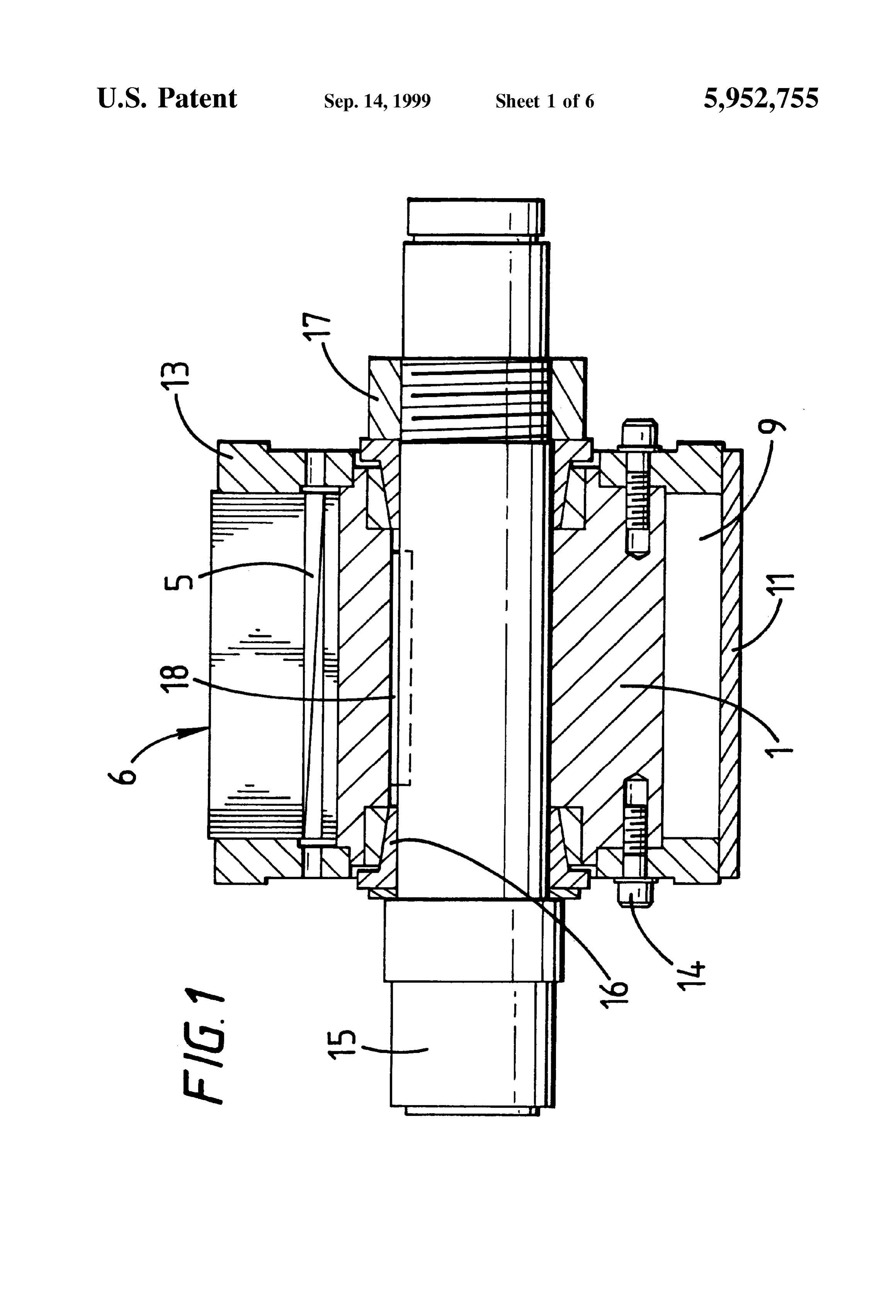
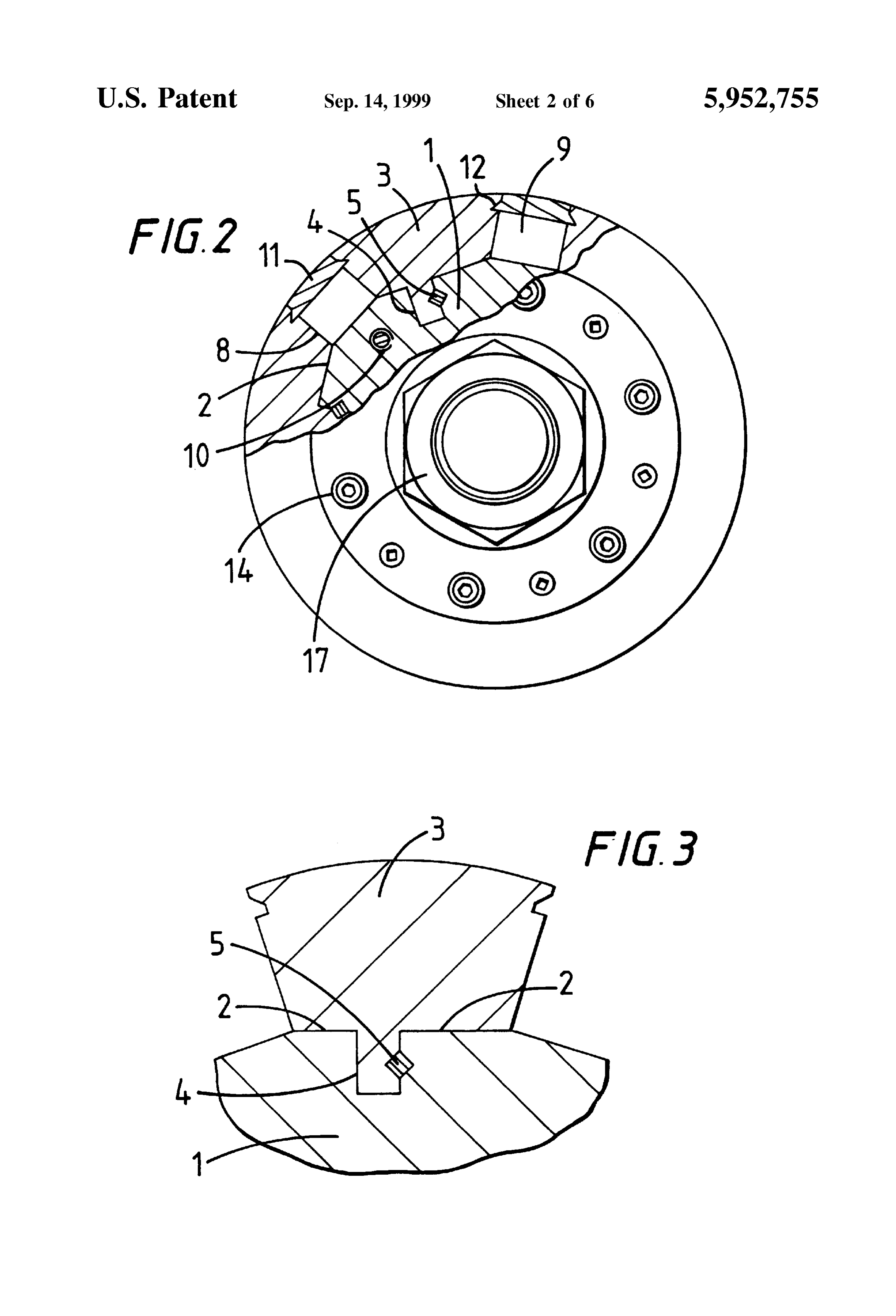
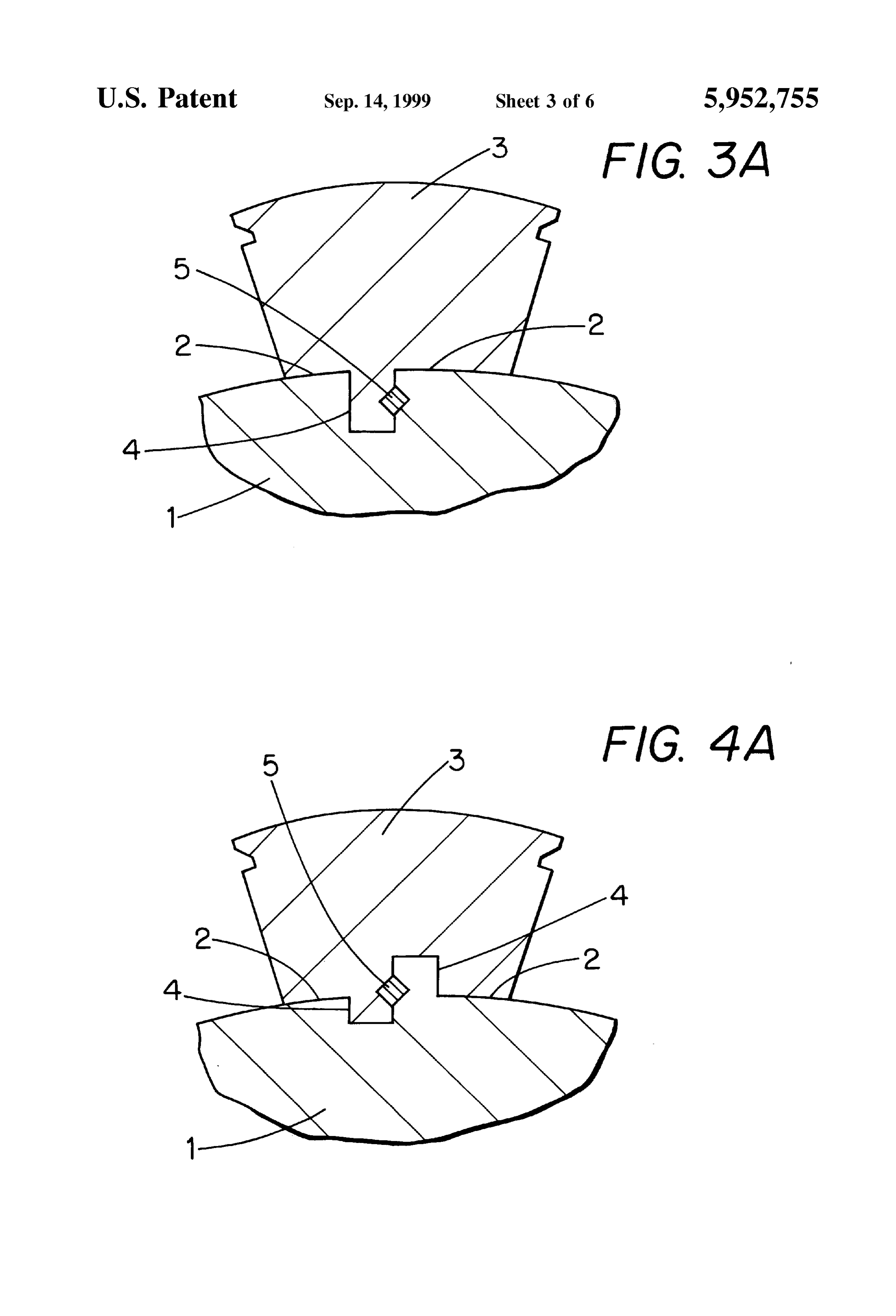
BRIEF DESCRIPTION OF THE DRAWINGS of the pole pieces 3 which are oriented by the positioning Surface 4.
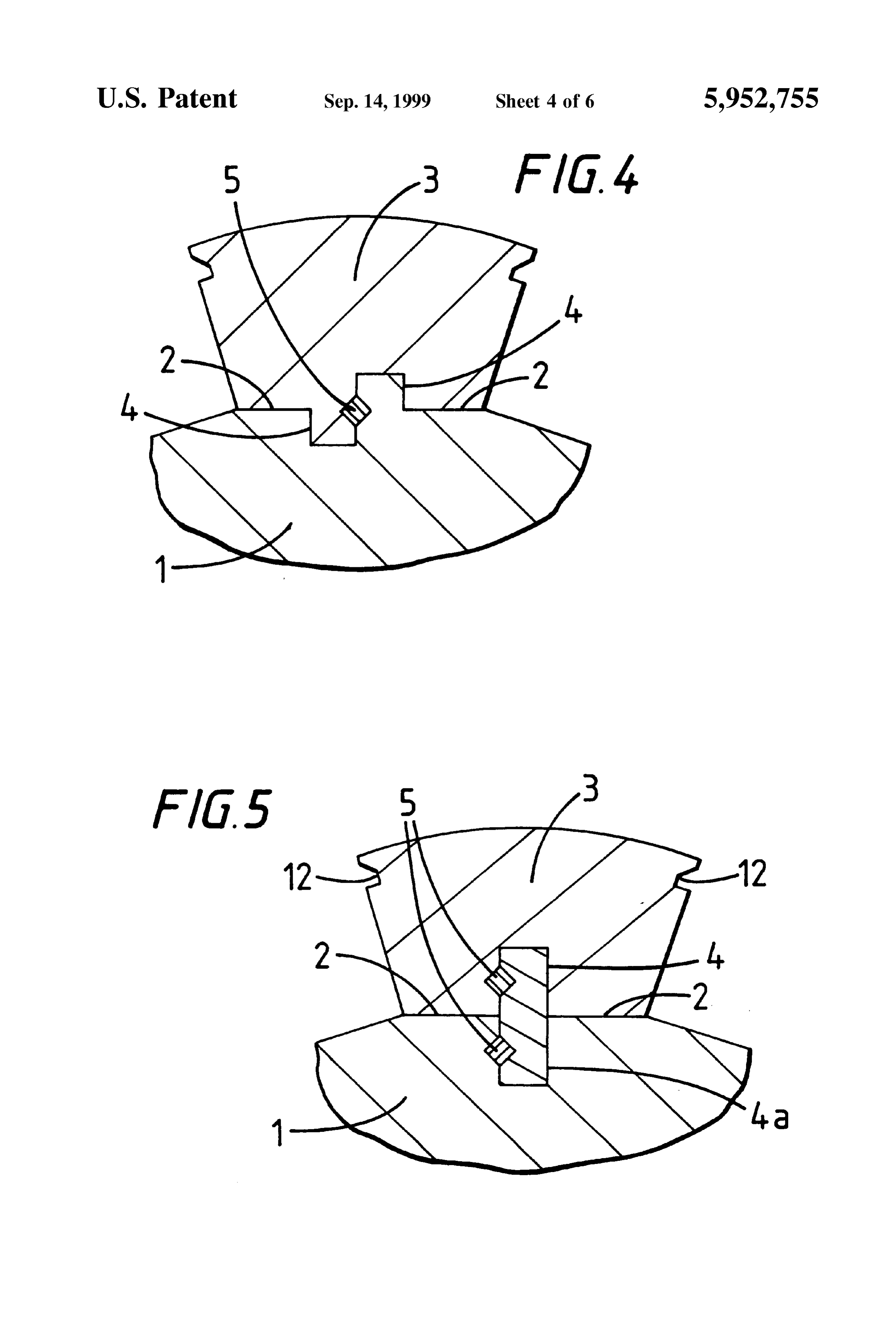
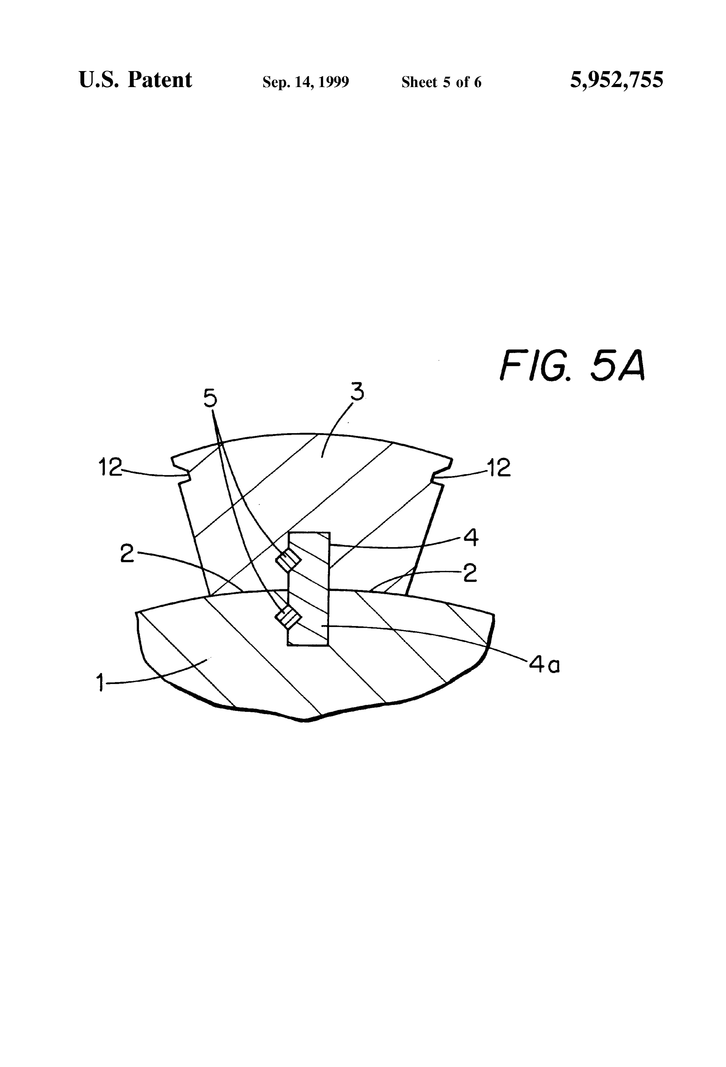
Further objects and advantages of the present invention will be more fully appreciated from a reading of the detailed As shown in FIGS. 4 and 5, the surfaces 4 controlling the description when considered with the accompanying draw angular orientation of the pole pieces need not be located at ings wherein: a greater radial distance from the centerline of the rotor than FIG. 1 is a longitudinal sectional view of a shaft and a the radial positioning surfaces 2. As illustrated in FIG. 5 the angular orientation Surfaces 4 may be formed by projections permanent magnet motor rotor in accordance with the inven 4a of rotor core material which engage corresponding slots tion;
FIG. 2 is an end View partly in Section of a permanent projections pieces 35 in the pole 3 and are secured therein by keys 5. The 4a may be manufactured as an integral part of magnet motor rotor in accordance with the invention; the core rotor hub 1 or as an assembly of independent FIG. 3 is an illustration of a pole piece positioned in the Segments that are Secured to the core rotor hub 1 as well as permanent magnet motor rotor in accordance with the inven to the pole pieces by keys 5.
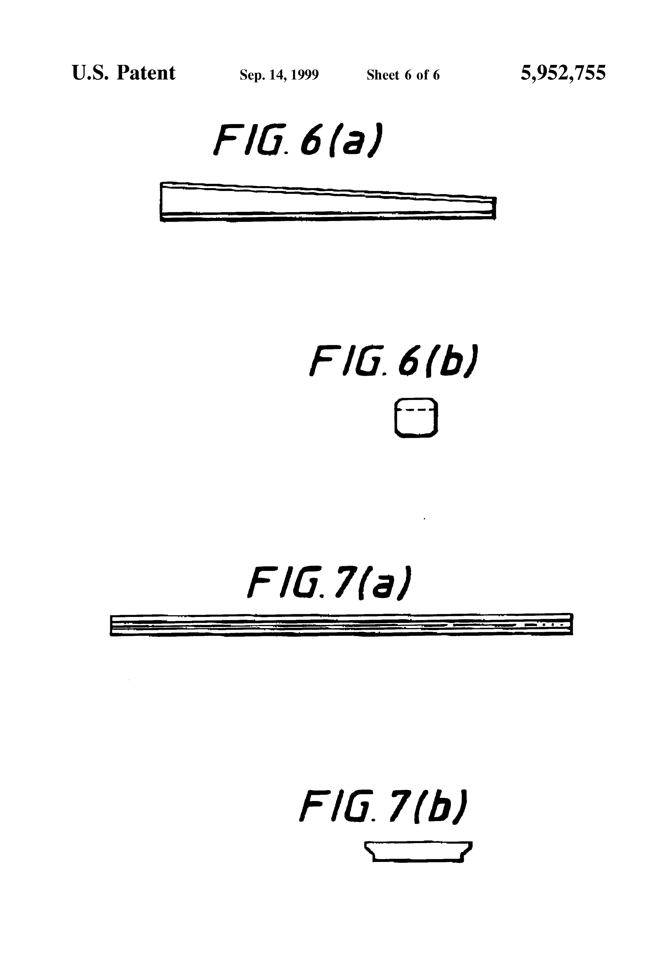
tion; The pole pieces are installed in the rotor hub by inserting FIG.3(a) is an illustration of a pole piece positioned in the 40 them radially onto the hub core 1. The pole pieces 3 are then permanent magnet motor rotor using curved radial position locked into position on the hub core 1 by inserting two ing Surfaces in accordance with the invention; overlapping multiple part tapered keys 5 of the type shown FIG. 4 is an illustration of a pole piece positioned in the in FIGS. 6(a) and 6(b) axially from one or both ends of the permanent magnet motor rotor in accordance with the inven 45 rotor assembly. When driven into place, the keys 5 produce tion in which the angular orientation Surface of the rotor is a wedging action which ensures the correct orientation of located at a lesser radial distance from the centerline of the pole pieces 3 in relation to the positioning Surfaces 2 and 4. rotor than the Surfaces which control the radial position of A Single magnet or a plurality of Smaller magnets 9 may the pole piece; be inserted axially from one or both ends of the rotor core FIG. 4(a) is an illustration of a pole piece positioned in the 50 between the pole pieces 3 after the pole pieces are in place permanent magnet motor rotor using curved radial position on the rotor hub 1. Temporary guide rails (not shown) guide ing Surfaces and in which the angular orientation Surface of the appropriately sized magnets into the rotor core. Threaded the rotor is located at a lesser radial distance form the center axial holes 10 in the face of the rotor hub core 1 may be used line than the radial position Surfaces in accordance with the to attach the temporary guide rails.
invention; 55 Generally, the magnets 9 have a rectangular shape with FIG. 5 is an illustration of an alternate arrangement for flat Sides. In an alternate embodiment, the magnets 9 may positioning a pole piece in the permanent magnet motor have a concave Surface which contacts a cylindrical rotor rotor in accordance with the invention; core surface. The relative size of the magnets 9 in relation to FIG. 5(a) is an illustration of an alternate arrangement for the size of the pole pieces 3 may be decreased or increased positioning a pole piece including curved radial positioning 60 as necessary to provide desired magnetic field Strength when Surfaces in accordance with the invention; using different magnetic materials. The magnets 9 are sized FIGS. 6(a) and 6(b) are side and end views, respectively, for a close clearance fit with the adjacent pole piece faces 8 showing a representative tapered key for locking a pole which are parallel plane Surfaces. Thus the magnets 9 are piece into a rotor; and held captive in the rotor assembly without being Subject to FIGS. 7(a) and 7(b) are side and end views, respectively, 65 any bearing loads.
along a representative slot wedge for retaining a pole piece The magnets 9 are restrained from moving radially out in the rotor. Wardly due to centrifugal loading by inserting slot wedges
Page 10
S 6 11, shown in FIGS. 7(a) and 7(b) which are made of 2. A permanent magnet motor rotor according to claim 1 magnetically inert material, into slots 12 formed in the rotor wherein the rotor hub includes a plurality of flat surfaces for pole pieces on the opposite Sides of the magnets 9. The Slot radially positioning the pole pieces and wherein each flat wedges 11 are held captive by mechanically engaging the Surface is tangential to an inscribed circle concentric with slots 12 in the rotor pole pieces 3. Alternatively, the rotor the axis of the rotor hub.
pole pieces 3 may be formed with Suitable projections to be 3. A permanent magnet motor rotor according to claim 1 received in and thereby retain the slot wedges 11. In a further wherein the rotor hub includes a plurality of curved surfaces embodiment, the slot wedges 11 may be restrained by end for radially positioning the pole pieces and wherein the plates 13, shown in FIG. 1, rather than by the slots 12 or by plurality of curved Surfaces form part of a cylinder concen projections in pole pieces. The slot wedges provide physical tric with the axis of the rotor hub.
protection for the magnets 9 during installation of the rotor 4. A permanent magnet motor rotor according to claim 1 assembly 1 into the Stator assembly and Shield the magnets further comprising a plurality of Slot wedge means disposed from the air gap Surfaces in the assembled motor or between adjacent pole pieces to retain the permanent mag generator, thereby reducing the Susceptibility of the magnets netS.
to demagnetization. 15 5. A permanent magnet motor rotor according to claim 4 The rotor pole pieces 3 and the magnets 9 are restricted wherein the Slot wedge means engage mating slots in the axially by magnetically inert end plates 13 which are pole pieces.
attached to the rotor hub 1 with fasteners such as Screws 14 6. A permanent magnet motor rotor according to claim 1 at both ends of the rotor shaft. The rotor core assembly 6 is further comprising a plurality of Slot wedge means disposed secured on a rotor shaft 15 by tapered metal portions 16 and between adjacent pole pieces to retain the permanent mag a shaft mounting locknut 17. Alternatively, the rotor core netS.
may be secured to the shaft by shrink fitting it on thereto 7. A permanent magnet motor rotor according to claim 6 rather than by using tapered wedge rings 16. A key extend wherein the Slot wedge means engage mating slots in the ing through the Shaft and rotor hub precludes relative pole pieces.
rotation of the Shaft and the rotor. In an alternate 25 8. A method of Securely positioning pole pieces and embodiment, the rotor hub and the rotor shaft may be permanent magnets in a permanent magnet motor rotor fabricated as a Single integral unit. comprising:
In an alternate embodiment, the outer Surfaces of the pole providing a plurality of angularly distributed Solid pole pieces may include circumferential grooves to reduce eddy pieces, current losses. In another embodiment the outer Surfaces of providing a rotor hub having at least two Surfaces which the pole pieces do not necessarily represent portions of a engage the pole pieces to position the pole pieces continuous cylindrical Surface. The outer pole piece Surfaces radially and in the angular direction, wherein the rotor may be shaped to control the magnetic flux distribution hub surfaces for positioning the pole piece in the acroSS the air gap to the motor or generator Stator. In a 35 angular direction include a plurality of flat Surfaces and further embodiment, the pole pieces may be positioned So as wherein each flat Surface is parallel to a radial plane to be skewed at an angle from a plane which coincides with which passes both through the axis of the rotor and the Shaft centerline. This serves to Smooth torque ripple. through the centerline of the pole piece; Another technique for Smoothing torque ripple is to skew the providing a plurality of permanent magnets disposed Stator core rather than the rotor core.
between the pole pieces, and
Although the invention has been described herein with providing a plurality of tapered key means for Securing respect to specific embodiments, many modifications and the pole pieces to the rotor hub, the key means being variations therein will readily occur to those skilled in the disposed between the pole pieces and the rotor hub. art. Accordingly, all Such variations and modifications are 9. A method of Securely positioning pole pieces according included within the intended scope of the invention. 45 to claim 8 comprising providing a rotor hub including a
I claim: plurality of flat Surfaces for radially positioning the pole 1. A permanent magnet motor rotor including a rotor core pieces and wherein each flat Surface is tangential to an assembly comprising: inscribed circle concentric with the axis of the rotor hub. a plurality of angularly distributed Solid pole pieces, 10. A method of Securely positioning pole pieces accord ing to claim 8 comprising providing a rotor hub including a a rotor hub having at least two Surfaces which engage the 50 plurality of curved Surfaces for radially positioning the pole pole pieces and position the pole piece radially and in pieces and wherein the plurality of curved Surfaces form part the angular direction, wherein the rotor hub Surfaces for of a cylinder concentric with the axis of the rotor hub. positioning the pole pieces in the angular direction 11. A method of Securely positioning pole pieces accord include a plurality of flat Surfaces and wherein each flat ing to claim 8 further comprising providing a plurality of Slot Surface is parallel to a radial plane which passes both 55 wedge means disposed between adjacent pole pieces to through the axis of the rotor and through the centerline retain the permanent magnets.
of a pole piece; 12. A method of Securely positioning pole pieces accord a plurality of permanent magnets disposed between the ing to claim 11 comprising providing mating slots in the pole pole pieces, and pieces and engaging the mating slots in the pole pieces with a plurality of tapered key means for Securing the pole 60 the slot wedge means.
pieces to the rotor hub, the key means being disposed between the pole pieces and the rotor hub. k k k k k
Provenance
- Collection
- Cited prior art
- Original PDF
- patentimages.storage.googleapis.com →
- Filed
- 1997-03-18
- Pages
- 10
- Method
- pdftotext (the PDF's own text layer) + pdftoppm 300dpi page scans
- Source
- Google Patents bibliographic record
- Granted
- 1999-09-14
- Inventors
- Michael J. Lubas; Electric Boat Corp
- Transcribed from
- patentimages.storage.googleapis.com →