patent · US5746576
Wind energy conversion device with angled governing mechanism
5 May 1998
Page 1 — bibliographic record
United States Patent 19 11 Patent Number: 5,746,576 Bayly 45) Date of Patent: May 5, 1998 54 WIND ENERGY CONVERSION DEVICE FOREIGN PATENT DOCUMENTS WITH ANGLED GOVERNING MECHANISM 120788 7/1984 Japan ....................................... 416/16 (75) Inventor: Elliott Bayly, Duluth, Minn. Primary Examiner Thomas E. Denion 3 W T n Attorney, Agent, or Firm-Haugen and Nikolai, P.A. 73) Assignee: World Power Technologies, Inc., (73) 3. Duluth, Minn. og 57 ABSTRACT A wind energy conversion device includes a support frame (21) Appl. No.: 662,995 that pivots on a vertical yaw axis, and a rotor/bushing assembly coupled to the support frame through a governing 22 Filed: Oct. 15, 1996 coupling that permits the rotor/bushing assembly to pivot on (51 int. Cl. ... F03B 7/00 a governing axis relative to the support frame. The govern 52 U.S. Cl. ................................................ 416/16: 416/12 ing axis is inclined from the vertical preferably by about 30° 58) Field of Search .................................... 416/9, 12, 13, to provide a substantial gravitational bias of the rotor/ 46/14, 16, 32 bushing assembly toward a normal operating position when wind velocities are below a predetermined threshold. The (56) References Cited governing axis also is laterally offset from a drive axis about which the wind rotates a propeller of the rotor/bushing
543,462 7/1895 Bramwell .................................... 469 assembly so that the drive axis intersects the yaw axis. As a 1698,709 1/1929 Bucklen et al. . result, wind induced thrust does not generate a torque about 1,746,991 2/1930 Buckden. the yaw axis. Wind velocities above the threshold pivot the 1,767.303 6/1930 Miller. rotorbushing assembly counter to the gravitational force. 1903,534 4/1933 Rime. thus to move a propeller structure of the rotor/bushing 2,026,828 1/1936 Dunn . assembly out of its normal orientation perpendicular to the 2,052,816 9/1936 Dunn. wind direction, thus reducing wind-induced thrust and rota 2,094.917 10/1937 Dunn. tional speed. A tail assembly, mounted to the support frame, 2,140,152 12/1938. Dunn. maintains the support frame in a predetermined angular
4,297.075 10/1981 Jacobs et al. . position relative to the wind direction as the rotor/bushing 4,439,105 3/1984 Hohenemser . assembly pivots. In an alternative construction, the tail 4,449,889 5/1984 Belden ...................................... 416/16 assembly is mounted to the rotor/bushing assembly, so that 4,518,312 5/1985 Jacobs et al. . governing action pivots and tilts the tail assembly.
5,295,793 3/1994 Belden. 25 Claims, 9 Drawing Sheets
Page 2
Drawing sheet — no readable text.
Page 3
Drawing sheet — no readable text.
Page 4
Drawing sheet — no readable text.
Page 5
Drawing sheet — no readable text.
Page 6
Drawing sheet — no readable text.
Page 7
Drawing sheet — no readable text.
Page 8
Drawing sheet — no readable text.
Page 9
Drawing sheet — no readable text.
Page 10
Drawing sheet — no readable text.
Page 11
WND ENERGY CONVERSION DEVICE The second general category of governor for wind energy WTH ANGLED GOVERNING MECHANISM conversion devices is known as a vertical governing or vertical tilting type, disclosed for example in U.S. Pat. No.
BACKGROUND OF THE INVENTION 2,026,828 (Dunn) and U.S. Pat. No. 4,767,939 (Calley). In 5 these devices the governing axis is horizontal, so that with
The present invention is directed to systems and devices for converting wind energy to electrical or mechanical increasing wind velocities the propeller and drive assembly power, and more particularly to governing apparatus for tend to pivot vertically upward out of the normal wind protecting such systems and devices from damage due to facing operating position.
abnormally high wind velocities. These devices are subject to design restrictions, such as O the need to prevent the tilting propeller from contacting the
Wind energy conversion devices, largely due to improved blade materials and aerodynamics, more reliability through tail, area which restricts the tail steering area to points below the occupied by the propeller in the fully governed position, out and improved generator/alternator magnets, are increas degrading performance and limiting design options. In ingly favored as a lower cost and more environmentally designs where the tail tilts downwardly as the propeller tilts sound approach to generating electricity. In remote areas 5 where power transmission over electrical lines is impractical upward, the effective steering moment is lost during or impossible, wind energy conversion devices may be the governing, leading to excessive rotation about the yaw axis. Further, rotor torque plays an undesirable role in vertically sole source of electric power, or a less costly source than tilting fossil fueled generators. Further, they are a useful supple about governors,the yaw by tending to rotate the propeller assembly axis during governing. Frequently this can mental or substitute power source, even when power trans lead to oscillatory behavior in which the propeller assembly mission lines are readily available. Beyond generating elec tilts partially back at high rpm trical power, these devices are also used to provide direct out of the wind because of theand rotor torque, yaws further torque, then slows down and mechanical power via gear trains and other mechanisms yaws back toward confronting the wind.
drivably coupled to the rotor or shaft driven by the wind.
All such devices, however, are subject to variations in 25 both Finally, the load springs acting on propeller assemblies in wind velocities. Calm weather entails velocities insufficient types of governors are subject to wear, and excessive accumulation to generate useful mechanical or electrical power. At the constant is increasingly of force as a spring with a given spring opposite extreme are high wind velocities (e.g. 60 mph) that compressed or extended. can drive movable components excessively beyond normal Therefore, it is an object of the present invention to operating tolerances, damaging the mechanical or electrical 30 provide a governing device for a wind energy conversion components of the device. The energy or force due to the apparatus that can function effectively without loading wind increases in proportion to the cube of the velocity. springs, either in compression or in tension. Thus, during a 60 mph gust of wind a device is subject to Another object is to provide a governing device for a wind forces eight times the forces experienced during a 30 mph power generator capable of biasing the propeller assembly wind. Given the prohibitive cost of designing components 35 into a normal operating position entirely due to gravity, yet that withstand the extreme forces, the affordable alternative is not subject to the oscillatory behavior characteristic of is a governing mechanism to reduce the effect of the extreme vertically tilting governors at high wind velocities. forces. A further object is to provide a governing device for a A wide variety of governing schemes have been devel wind energy conversion system that permits selective ben oped. These include whole blade pitching mechanisms, air eficial use of rotor torque as a factor to either control rpm or foil spoilers or flaps, blade tip brakes and ailerons. Of greater to enhance governing.
interest in the present context is a class of governors that It further is an object to provide a governing mechanism passively rotate the propeller plane out of the direct path of having the performance advantages of the horizontally gov the wind. In general there are two categories of this type of erning type, that also eliminates the horizontal offset of the governor. The first is known as a horizontally governing or 45 propeller axis from the yaw axis, avoiding the energy folding-tail approach. Typically a propeller assembly and a penalty due to the wind force rotating the propeller plane tail assembly pivot relative to one another about an essen away from its most efficient angular position, i.e. perpen tially vertical governing axis, with a drive axis of the dicular to the wind direction.
propeller assembly offset from the vertical tower axis or Yet another object is to provide a more efficient, simpler "yaw” axis. As a result, wind at increasing velocity tends to 50 and lower cost governing device for a wind energy conver rotate the propeller assembly about the yaw axis, against the sion system.
tendency of the tail assembly to maintain its angular position relative to the wind direction. As wind velocity increases, SUMMARY OF THE INVENTION such rotation progressively moves the propeller plane from To achieve these and other objects, there is provided a its maximum efficiency position perpendicular to the wind 55 wind energy conversion apparatus. The apparatus includes a direction, thereby reducing the wind thrust. Examples of this rotor shaft and a propeller structure mounted to the rotor approach are found in U.S. Pat. No. 1.746,991 (Bucklen) shaft for transferring a wind-induced torque to the rotor shaft and U.S. Pat. No. 4,297.075 (Jacobs). to rotate the rotor shaft about a drive axis and provide a The horizontal offset of the tower axis from the drive axis wind-induced thrust acting along the drive axis. The appa reduces efficiency, because any wind, no matter how low the ratus further includes a support assembly for supporting the velocity, generates a torque that tends to rotate the propeller rotor shaft. The support assembly is comprised of: (i) a assembly and tail assembly about a vertical yaw axis of the support frame mounted to pivot on a substantially vertical device. Attempts to overcome this problem include an extra yaw axis; (ii) a bushing structure supporting the rotor shaft vane as in U.S. Pat. No. 1903,534 (Rime), and a bevel gear for rotation about the drive axis; (iii) a speed-governing arrangement to promote pivoting responsive to rotor torque 65 coupling for mounting the bushing structure to pivot relative as in U.S. Pat. No. 1,767.303 (Miller). These devices, in and to the support frame about a governing axis, in first and of themselves, are drains on the available energy. second opposite arcuate directions respectively toward and
Page 12
away from a normal operating position in which a vertical The inclination of the governing axis from vertical, and its plane containing the drive axis is substantially parallel to a horizontal offset from the drive axis. can be selected with wind direction, wherein the governing axis is laterally offset reference to the design thrust on the drive shaft as a function from the drive axis, inclined at least about 20 degrees from of wind velocity. In effect, setting these parameters selects a the horizontal, and inclined from the vertical to bias the threshold wind velocity at which the moment about the bushing structure in the first arcuate direction toward the governing axis due to thrust overcomes the force of gravity normal operating position due to gravity; and (iv) a first stop to pivot the rotor shaft and the bushing structure out of the means for preventing travel of the bushing structure in the normal, non-governed position. A typical threshold velocity first arcuate direction beyond the normal operating position. is 25 mph, although anticipated wind conditions and design The conversion apparatus further includes a tail assembly 10 parameters call for a range of appropriate threshold veloci mounted to the support assembly, extending away from the ties.
support assembly and tending to seek a selected angular Thus in accordance with the present invention, a govern alignment relative to the wind direction. The tail assembly ing device for wind energy conversion systems can function thereby tends to pivot the support assembly about the yaw entirely by gravity, without springs or other mechanical axis toward a selected angular position relative to the wind 15 loading devices, although such devices can be added to direction. influence the governing response if desired. At the same In a preferred approach, the tail assembly is mounted to time. the governing device can operate free of the oscillation the support frame and has a tail axis within a vertical tail tendency and excessive yaw rotation characteristic of ver assembly plane. The drive axis is substantially horizontal tically tilting governors. Because of the horizontal offset of and parallel to the tail assembly plane. More preferably, in the governing axis, the governing device operates without the normal operating position the yaw axis, the tail axis and the need to offset the drive axis from the yaw or tower axis. the drive axis all lie in the same plane, with the drive axis Reliance on gravity reduces the cost and complexity of the and tail axis both intersecting the yaw axis. Then there is no governing device, and provides smoother, more predictable horizontal offset of the drive axis and tail axis in the normal behavior under varying wind conditions. Rotor torque can operating position, leading to improved efficiency under 25 be used to control rpm or to enhance governing action. normal, non-governed operating conditions. Governing action is subject to the degree of tilt of the As an alternative, the tail assembly can be mounted governing axis, the weight of the rotor and bushing directly to the bushing structure, in which event the tail structure, and location of the bushing structure/rotor center assembly pivots with the bushing structure about the gov 30 of mass relative to the governing axis, to provide a consid erable degree of freedom in selecting design parameters.
erning axis.
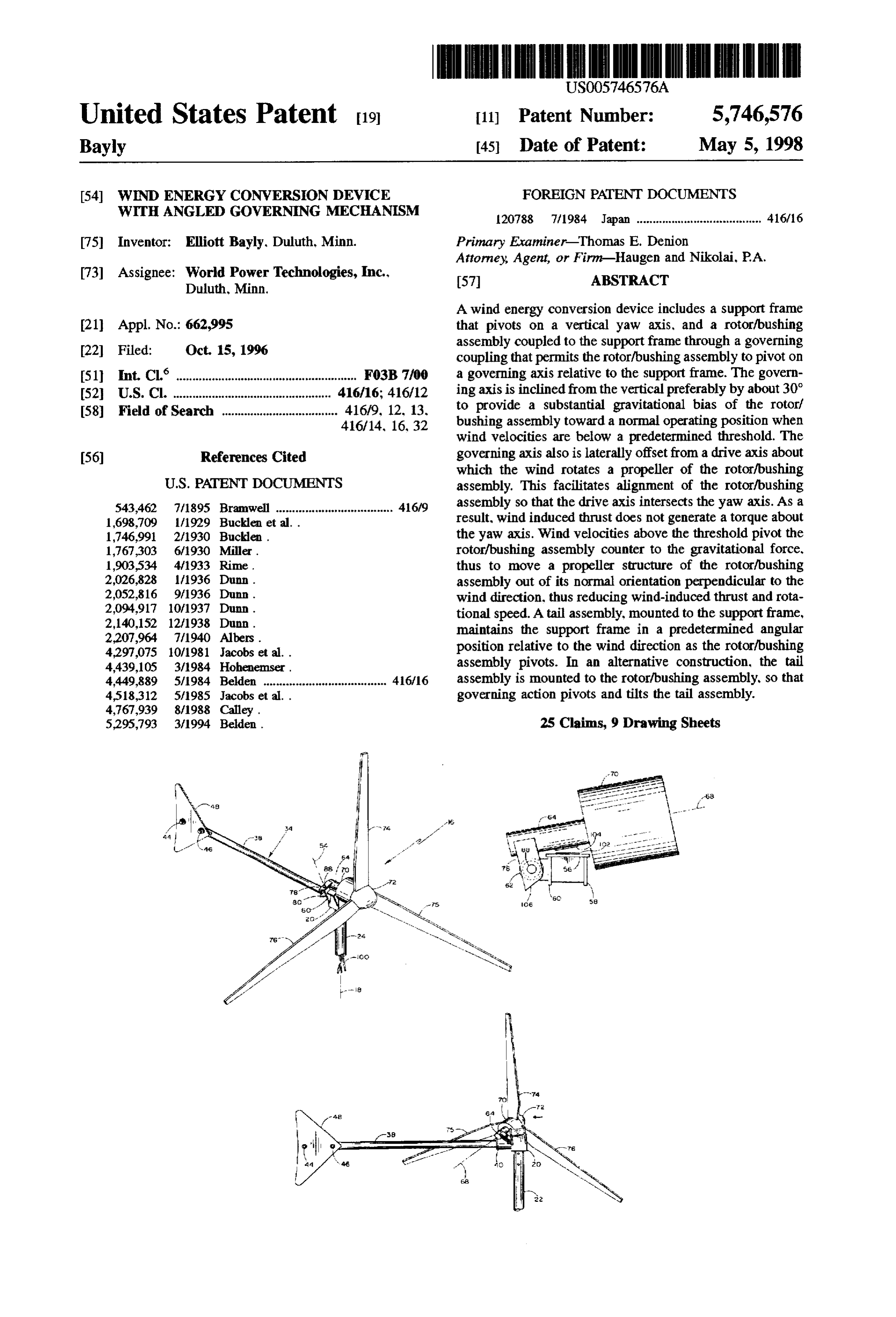
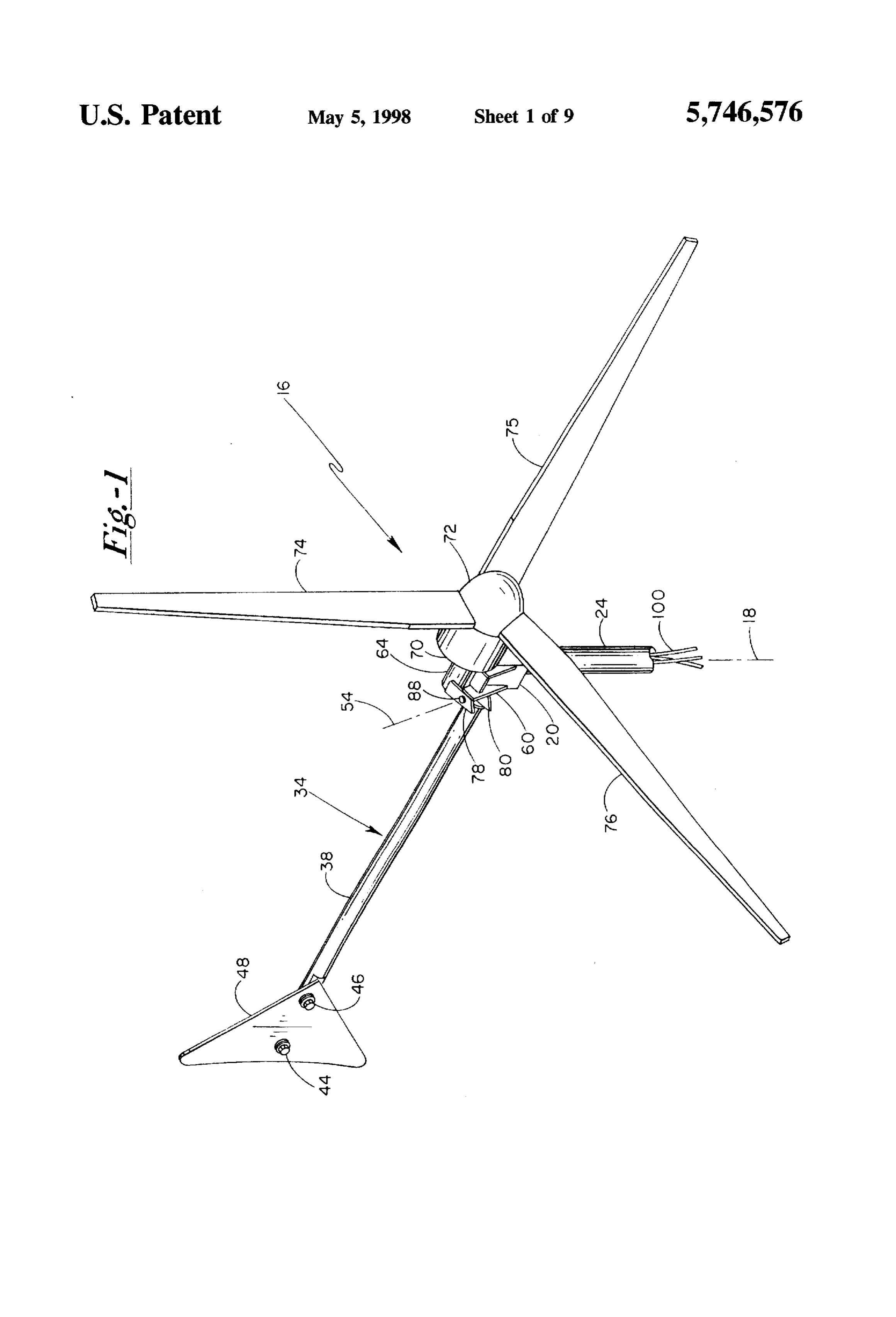
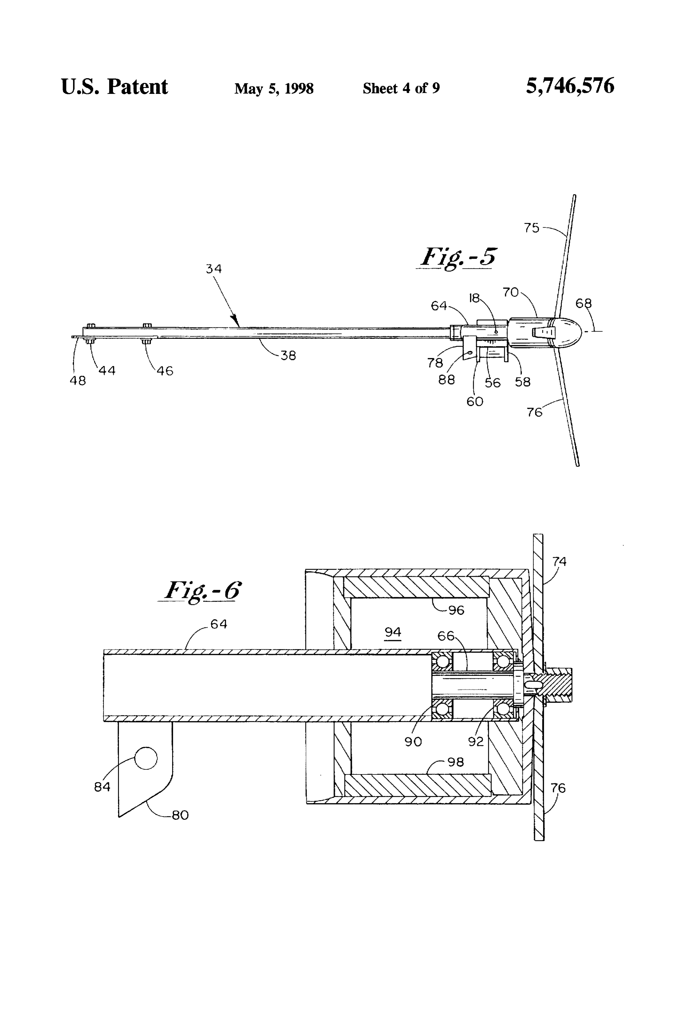
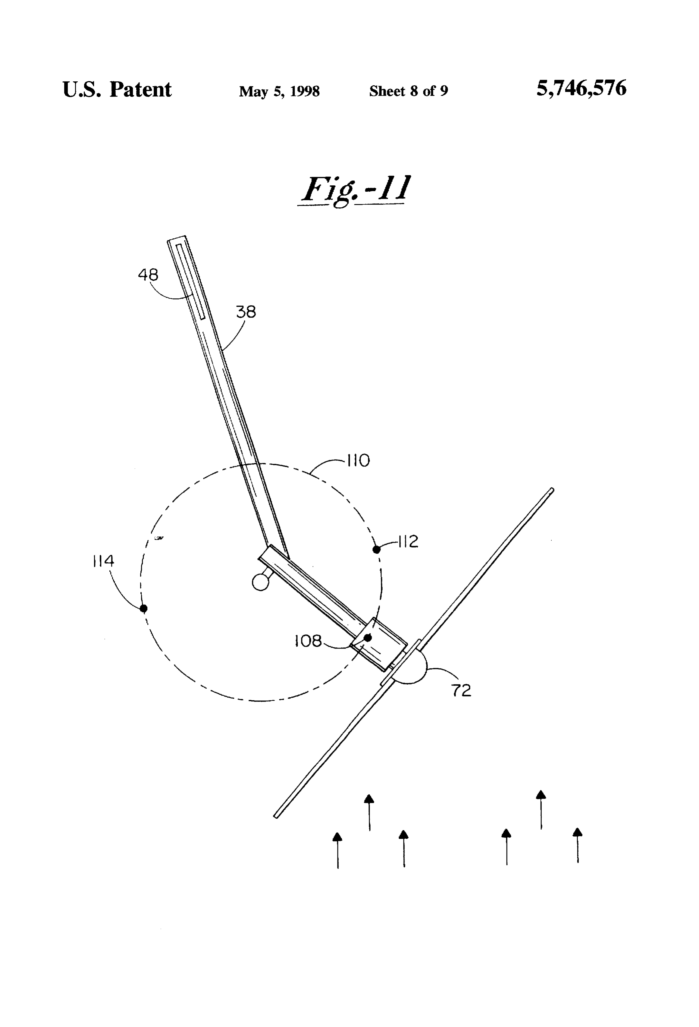
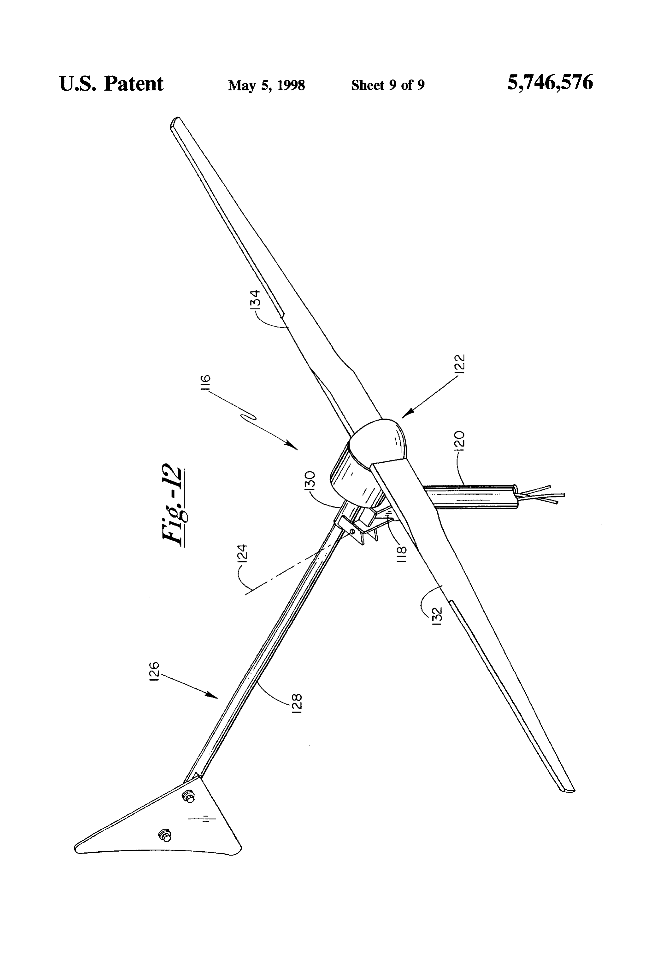
Inclining the governing axis at least about 27 degrees IN THE DRAWTNGS from the horizontal substantially diminishes the undesirable oscillation and torque effects characteristic of vertical tilting For a further understanding of the above and other fea governors. Even more preferably, the governing axis is 35 tures and advantages, reference is made to the following inclined at least 45 degrees from the horizontal. An angular detailed description and to the drawings, in which: offset of the governing axis from the vertical is required for FIG. 1 is a perspective view of a wind energy conversion gravitational biasing of the bushing structure toward the device constructed according to the present invention; normal operating position. The degree of tilt of course FIG. 2 is an exploded parts view of the wind energy influences the degree of such bias. Generally the governing conversion device (propeller removed);
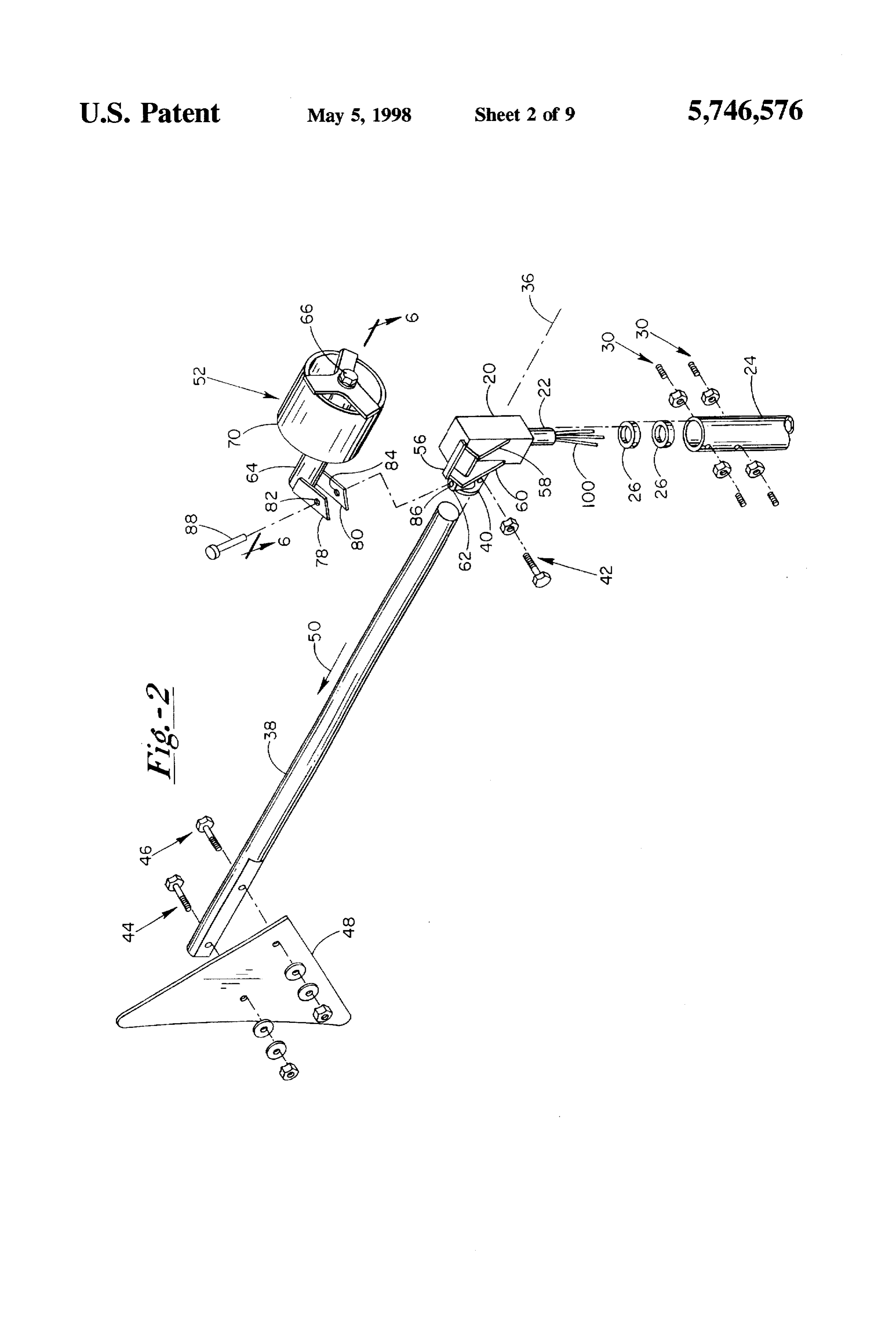
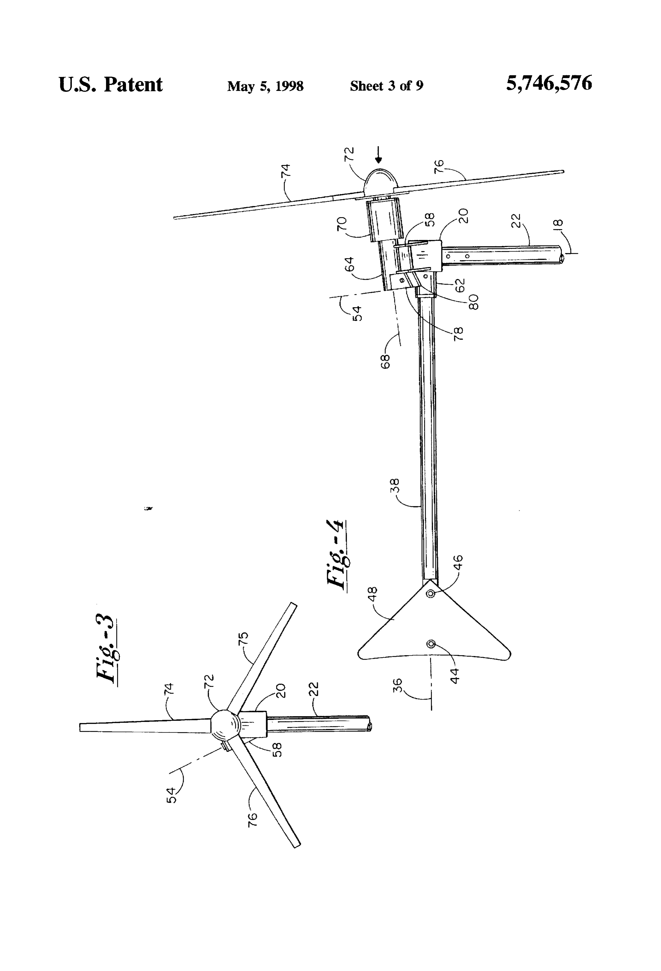
axis is inclined from the vertical at least 10 degrees, and FIG. 3 is a front elevation of the device; more preferably at least 18 degrees. The governing axis also FIG. 4 is a side elevation of the device in its normal is horizontally offset from the drive axis, facilitating effec tive governing combined with the most efficient alignment operating position;
of the drive, tail and yaw axes as previously noted. 45 FIG. 5 is a top view of the device; In short, there is a preferred range of inclination from FIG. 6 is a sectional view taken along the line 6-6 in about 27 to about 72 degrees from the horizontal (30-80 FIG. 3;
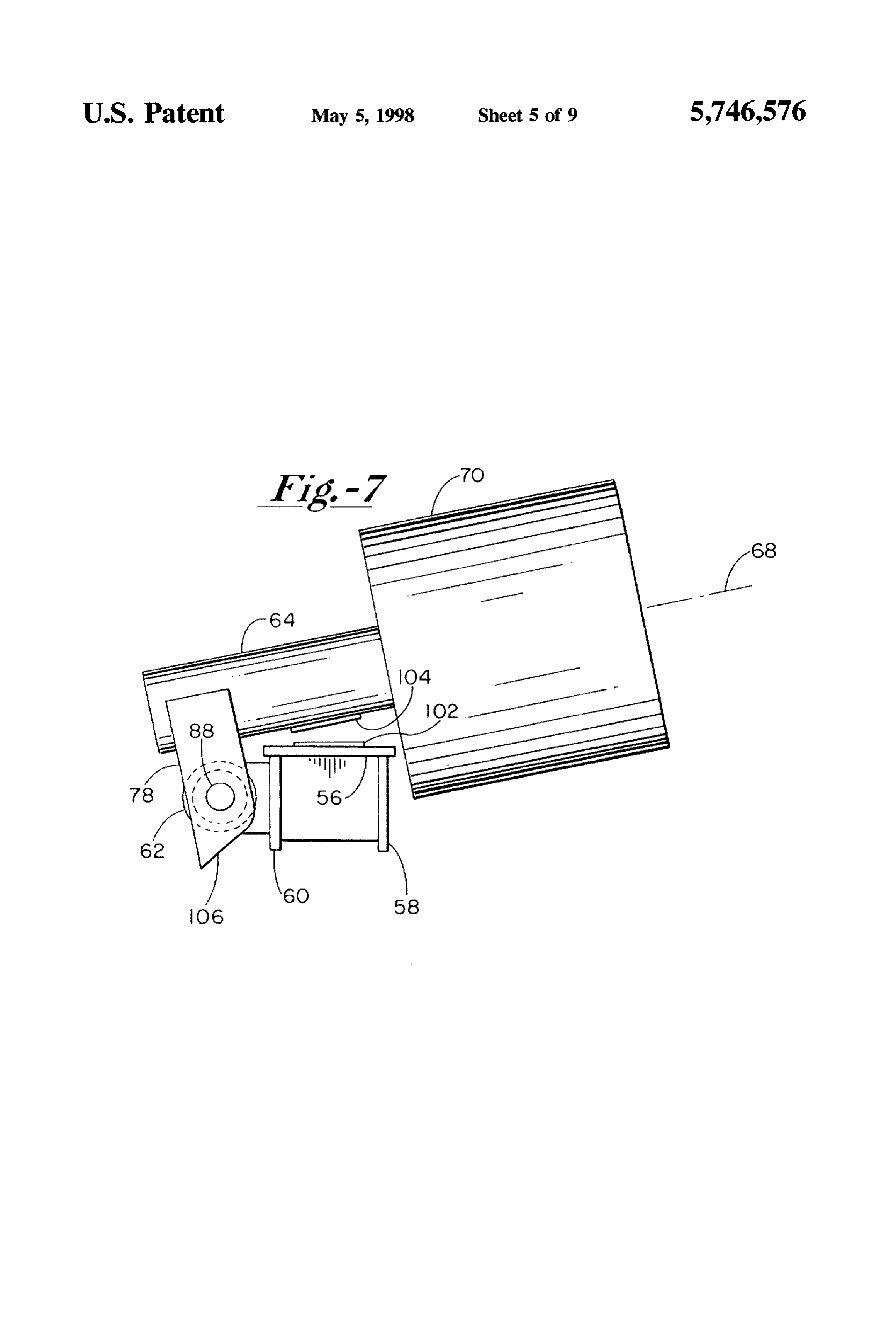
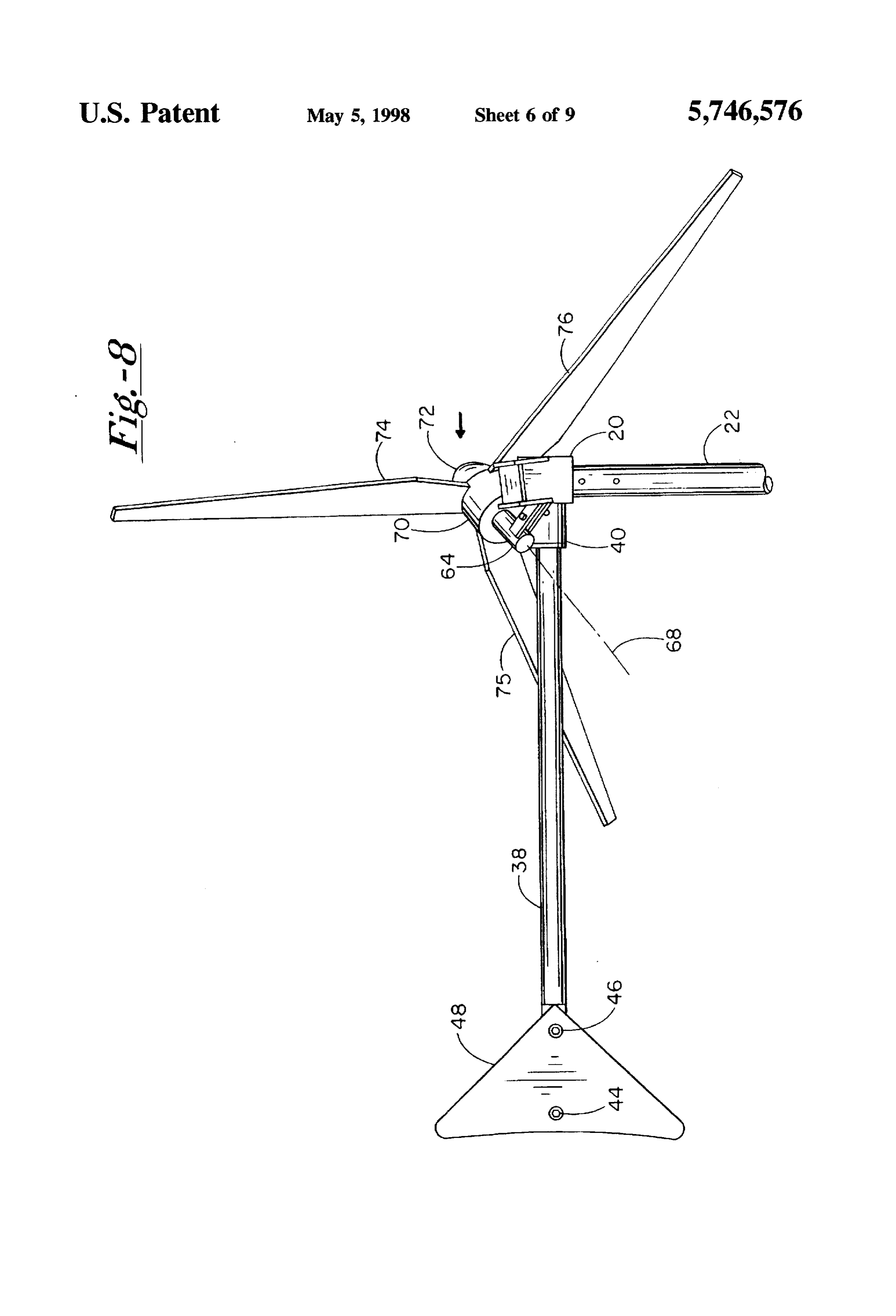
percent vertical), with governors having lower or "more FIG. 7 is an enlarged view of a portion of the device, taken horizontal" inclines tending to behave more like vertically from a plane normal to the governing axis; tilting governors, and vice versa. 50 FIG. 8 is a side elevational view of the device in a fully The propeller structure can be configured to rotate the governed position;
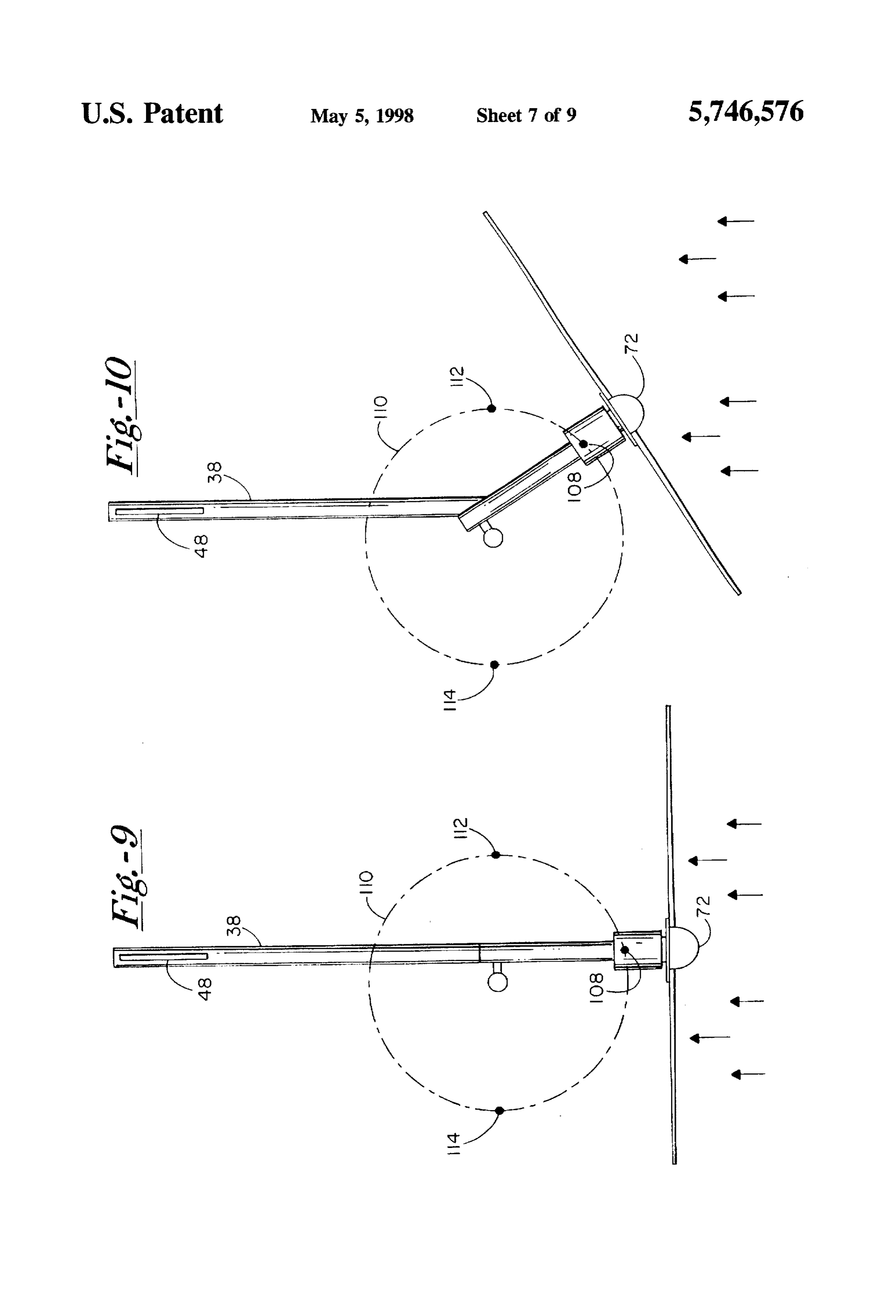
drive shaft in a direction that either promotes or counteracts movement of the bushing means in the second arcuate theFIGS. 9-11 are schematic views from the plane normal to governing axis, showing the device in respective normal, direction, i.e. either to promote or to counteract governing. partially governed and fully governed states; and When counteracting governing, rotor torque tends to bias the 55 FIG. 12 is a perspective view of an alternative wind propeller plane toward its wind-confronting angle despite increasing wind velocities, but also helps prevent rotor energy conversion device constructed according to the overspeed by tilting the propeller axis further away from the present invention.
wind in the event of an intentional or accidental load loss. DETALED DESCRIPTION OF THE If desired, the propeller structure and rotor can be inclined PREFERRED EMBODIMENTS in the normal operating position for tower clearance, e.g. to incline the drive axis at an angle of 1-8 degrees from the Turning now to the drawings, there is shown in FIGS. 1-8 horizontal. Typically the governing axis is also inclined so a wind energy conversion device 16. FIG. 2 shows the that it remains parallel to the propeller plane, but the device in an exploded-parts view. Typically, device 15 is governing axis need not be inclined to match the tower 65 mounted on a tower (not shown) to pivot on a vertical axis clearance tilt. In either event, the governing action is essen 18 referred to as the yaw axis. More particularly the device tially the same. includes a support frame or yaw frame 20 with a down
Page 13
wardly depending yaw shaft or vertical column 22 mounted offset from the vertical by the same angle. This offset, within a vertical pipe or sleeve 24 of the tower through typically 1-8 degrees, is for tower clearance, to avoid any bushings 26 and 28. Fastener assemblies 30 secure the interference between the propeller blades and the tower bushings. The vertical sleeve is at the top of the tower. Ball structure. More particularly, the tilt reduces the distance by bearings (not shown) located inside support frame 20 allow which the propeller and alternator need to be longitudinally the frame to rotate on yaw shaft 22. about yaw axis 18. spaced apart from the yaw axis. Even when at the 8 A tail assembly or rudder assembly 34 is secured to maximum, the clearance tilt has little impact on support frame 20 and extends away from the support frame performance, as compared to a horizontal drive axis/vertical along a horizontal tail axis 36 (FIG. 2). The tail assembly propeller plane design.
includes an elongate tail shaft38, the proximal end of which 10 It further is apparent from FIG. 4 that inclined support is secured within a tail mounting sleeve 40 of the support members 58 and 60 likewise reflect the clearance tilt. frame by a fastener assembly 42. At the distal end of the tail Consequently governing axis 54 is parallel to the propeller shaft, fastening assemblies 44 and 46 secure a tail vane 48. plane, i.e. with the same offset from the vertical as that The tail assembly, particularly due to tail vane 48, tends plane, in addition to the approximately 300 offset shown in to seek an angular alignment downwind of support frame 20 15 FIG. 3. This need not be the case, however. Without sub thus to maintain the support frame at a selected angular stantially affecting performance, sleeve 62 and brackets 78 position relative to the wind direction. More particularly, tail and 80 can be positioned to define a governing axis that vane 48 aligns tail shaft 38 into parallelism with the wind would appear as a vertical line in FIG. 4. direction, with wind blowing from the proximal end of the 20 The alignment of drive axis 68 and tail axis 36 in a shaft toward the distal end as indicated by the arrow at 50. common vertical plane under normal operating conditions is A rotor/bushing assembly 52 is mounted to support frame best seen in FIG.S. Tail assembly 34 and governing axis 54 20, to pivot relative to the support frame about a governing (pin 88) are downwind of yaw axis 18, while the propeller axis 54 (FIGS. 3 and 4). Frame 20 has a support structure structure including blades 74–76 is upwind of the yaw axis. including a plate 56, forward and rearward inclined support 25 The center of mass of assembly 52 also is upwind of the yaw members 58 and 60 fixed to the plate, and a governing sleeve axis, clue primarily to the weight of the propeller structure 62 secured to rearward inclined member 60. and an alternatorirotor assembly that includes casing 70. Assembly 52 has a bushing structure including an elon The alternator/rotor assembly, as shown in FIG. 6. gate rotor sleeve 64. Sleeve 64 supports a rotor shaft 66 includes rotor shaft 66 supported rotatably within rotor (FIG. 6) for rotation about a substantially horizontal drive 30 sleeve 64 by bearings 90 and 92. Immediately surrounding axis 68 (FIGS. 4 and 5). An alternator casing 70 is coaxial sleeve 64 and integral with the sleeve is a stator 94 formed with and surrounds the rotor sleeve. At the forward end of of insulated copper wire windings. Casing 70 surrounds the casing is a nose cone 72. A propeller structure integral stator 94, but is integral with rotor shaft 66 and rotates with with rotor shaft 66 includes three propellerblades 74, 75 and the shaft and propeller assembly. A set of permanent 76. 35 magnets, two shown at 96 and 98, are mounted to the inside Upper and lower rotor sleeve mounting brackets 78 and surface of casing 70. When casing 70 rotates responsive to 80 extend away from a rearward end of the rotor sleeve in the wind, the moving magnetic field due to the magnets a direction perpendicular to the drive axis. Brackets 78 and interacts with the stator windings to generate the desired 80 are spaced apart from one another a distance slightly electrical current, which is provided to the intended use via greater than the length of governing sleeve 62, so that the conductors 100 (FIG. 2) electrically coupled to the stator brackets are positionable adjacent opposite ends of the windings. More specifically, conductors 100 are coupled to sleeve, with openings 82 and 84 of the brackets aligned with the stator through a brush and slip ring (not shown) that an opening 86 through sleeve 62. A pin 88 extends through maintain the electrical coupling while permitting the stator openings 82-86 when the brackets and sleeve are so aligned, to pivot with support frame 20 about the yaw axis. thus to mount the bushing structure for pivoting with respect 45 As mentioned above, normal operating conditions con to support frame 20 about the governing axis. template wind velocities up to a predetermined threshold, Asbest seen in FIG. 3, governing axis 54 is inclined from e.g. 25 mph. If the propeller plane continues to confront the a vertical plane containing tail axis 36, by an angle of about wind during episodes of velocities above the threshold, 30 degrees-in other words, about 60 degrees from the excessively high levels of thrust and rpm can overload horizontal. Considering drive axis 68 (shown as a point in 50 electrical components and subject structural components to FIG. 3) as a longitudinal axis, governing axis 54 is trans undue stress and strain, risking serious and permanent versely or laterally offset from the drive axis. Thus, wind damage to these components.
thrust acting along drive axis 68 tends to pivot assembly 52 To minimize the risk of damage, rotor/bushing assembly about governing axis 54 relative to the support frame. As is 52 is configured to pivot about governing axis 54 in response later explained, gravity alone can prevent such pivoting until 55 to wind velocities beyond the threshold. This pivots the wind velocity exceeds a predetermined threshold, so that propeller plane away from the normally perpendicular rela under normal operating conditions (speeds below the tion to the wind direction, even while tail vane 48 maintains threshold) the components are aligned as shown in FIG. 3. the angular position of support frame 20 with respect to the Further, it is apparent from FIG. 3 that under normal wind. As wind velocity increases further above the operating conditions, the vertical plane containing tail axis threshold, the degree of pivoting increases, until the bushing 36 also contains drive axis 68 and yaw axis 18. Thus, under assembly reaches, a fully governed position illustrated in normal operating conditions the wind thrust acts within this FIG.8. When velocities fall below the threshold, the bushing common plane, creating no moment arm to rotate support structure returns to the normal operating position shown in frame 20 or assembly 52 about the yaw axis. This increases FIG. 4.
efficiency as compared to conventional folding tail designs. 65 In device 16, the bushing structure is continually urged As seen in FIG.4, drive axis 68 is slightly offset from the into the normal operating position due to gravity alone; there horizontal, and a plane containing propeller blades 74-76 is need be no springs or other biasing members. Governing
Page 14
occurs when the wind induced thrust creates a rotational sive to gain abrupt decrease in wind velocity. The first moment about governing axis 54 sufficient to overcome the concern favors a larger incline, while the second concern gravitational force. For a given rotor/bushing assembly, this favors a more gradual incline. Yet another consideration is depends on the governing axis tilt and its lateral offset from the degree to which torque from propeller rotation is either the drive axis. allowed or intended to influence governing. More FIG. 7 shows portions of support frame 20 and assembly particularly, the greater the degree of incline from vertical up 52, with the assembly in a partially governed position to to about 45 degrees, the more pronounced is the effect of reveal a space between a pad 102 on plate 56 and a pad 104 rotor/propeller torque.
mounted to rotor sleeve 64. Because of the incline of As the above implies, the inclined governing axis permits governing axis 54, gravity biases sleeve 64 toward plate 56. 10 use of rotor/propeller torque to influence governing behav Thus, pads 102 and 104 together function as a stop that ior. With reference to FIG. 3, with governing axis 54 offset determines the normal operating position of assembly 52, by to the left of drive axis 68 as shown, and with the propeller preventing the rotor/bushing assembly from rotating clock configured to rotate counterclockwise, the upward tilt of the wise (as viewed in the figure) beyond the normal operating 15 drive axis caused by governing action introduces a rotor position. torque component that resists further upward tilting of the Another stop is provided for determining the fully gov drive axis. Thus, if during governing load is lost either erned position, by preventing assembly 52 from rotating accidentally or by design, the response to the loss of torque counterclockwise beyond that position. In particular, upper is for the drive axis to tilt more vertically, i.e. further away from the wind than if the load were present. This effect helps bracket 78 is formed with an inclined edge 106 remote from 20 prevent rotor sleeve 64. Bracket 80 has a similar edge aligned with rotor overspeed. The magnitude of this effect edge 106. As assembly 52 is pivoted counterclockwise into depends on the propeller blade length and the inclination of the fully governed position, edge 106 (and its counterpart on the governing axis. With reference to the preferred range of bracket 80) are moved into surface engagement with governing axis tilt from -he vertical, the torque effect is the inclined support member 60. Accordingly, the support mem 25 least at the preferred minimum tilt of about 18 degrees, and ber and brackets cooperate to provide the second stop. increases to a maximum at about 45 degrees of tilt. Together, the two stops define a limited arc for bushing On the other hand, if propeller blades 74 and 76 are structure travel, in this case approximately 60–700. The configured for clockwise rotation, rotor torque during gov arcuate path can exceed 700 if desired. Regardless of the erning augments governing by urging the drive axis to tilt arcuate path length, the fully governed position is set to 30 away from the horizontal. This increases the governing occur before assembly 52 reaches the zenith or "high point" response for a given tilt of the governing axis, assuming of a full circular path (assuming no stop means in either equality of other factors. Alternatively, this configuration direction) of the assembly center of mass, to ensure that even can provide an equivalent governing action at greater at the fully governed position, gravity biases the bushing degrees of governing axis incline from vertical. This permits structure back toward the normal operating position, i.e. in 35 a more positive gravitational hold at wind speeds below the the clockwise direction as viewed in FIGS. 7 and 9-11. If threshold.
spring force is added, the fully governed position can be FIGS. 9, 10 and 11 are schematic top plan views of device extended beyond the high point. 16 in the normal, partially governed and fully governed Likewise, pads 102 and 104 are positioned to ensure that positions, respectively. At wind velocities of 0-25 mph assembly 52 reaches a normal operating position before this (assuming 25 mph as the threshold velocity), the energy structure (more particularly its center of mass) reaches the conversion device remains in the normal position, with drive "low point" of the circular path. This, in turn, ensures the axis 68, tail axis 36 and yaw axis 18 in the same vertical desired gravitational bias in the normal operating position. plane. The approximate center of mass of the bushing The degree of gravitational bias, for a given weight and structure is indicated at 108. Gravity can be assumed to be configuration of the rotor/bushing assembly, is determined 45 acting upon the rotor? bushing assembly at mass center 108, continually urging clockwise rotation about governing axis by the governing axis. As this axis is inclined more from the 54.
vertical, the circular path of bushing structure travel The stop consisting of pads 102 and 104 prevents the becomes more inclined from the horizontal and thus has a bushing structure/rotor from rotating clockwise beyond the larger vertical component, which increases the gravitational normal position. A circular path 110 for the mass center has effect. 50respective high and low points 112 and 114. In terms of incline of the governing axis from the vertical, In the normal configuration, the propeller structure fully a broad range of angles is available to suit various design faces the wind, i.e. propeller blades 74 and 76 as they rotate considerations. The incline from vertical must be at least define a propeller plane that is perpendicular to the wind sufficient to provide the gravitational bias, but not so large direction indicated by the arrow. There is no horizontal offset as to cause the oscillatory or erratic behavior characteristic 55 of the drive axis from the tail axis. The propeller plane of vertical tilting devices. For example, the incline from remains perpendicular to the wind direction over the full vertical can range from about 10 degrees to about 70 range of normal, non-governed operation.
degrees. A more preferred range of incline from the vertical As wind velocities increase, e.g. to within a range of is from about 18 to about 53 degrees. Expressed another 25-35 mph, the moment arm about the governing axis due way, this preferred range can be thought of as from about 30 to wind induced thrust along the drive axis overcomes to about 30 percent of vertical. More preferably, the gov gravity and rotates the rotor/bushing assembly counterclock erning axis remains more vertical than horizontal, with the wise to the partially governed position. In FIG, 10, this degree of incline from the vertical less than 45 degrees. position is exemplary, the precise position depending on the Primary design considerations that influence the govern wind velocity. The effective propeller area facing the wind ing axis tilt include the amount of gravitational bias 65 can be represented by a projection of the actual propeller required, and the preference for a more gentle (reduced plane onto a plane perpendicular to the wind velocity. As shock and vibration) return to the normal position respon governing proceeds, the area of the projection decreases.
Page 15
which for a given wind velocity diminishes propeller rota The governing mechanism can be employed with a tail tional speed and thrust. assembly mounted either to the support frame or to the At full governing (FIG. 11), the rotor/bushing assembly bushing structure supporting the rotor shaft. In the former has pivoted 60-70 degrees about the governing axis, and the case, the incline of the governing axis can be combined with projection of the propeller area is a small fraction of the the lateral offset of the governing axis from the drive axis, actual area traversed by the propellers. Even at this point, to position the drive axis and tail axis in the same vertical wind thrust can cause additional pivoting of rotor/bushing plane as the yaw axis. This eliminates the energy production assembly 52 with support frame 20 and tail assembly 34 penalty due to the wind-induced moment arm about the yaw about yaw axis 18, further reducing the projection of the axis under normal, non-governed operation. Further, the propeller area. Such additional rotation includes rotation of 10 direction of incline of the governing axis can be selected tail assembly 34 as well, due to the contact of inclined edge with respect to the direction of rotation of the propeller and 106 against inclined member 60. As seen in FIG. 11, such rotor, so that the torque due to such rotation either assists additional pivoting moves tail shaft 38 out of alignment with governing or controls rpm as desired.
the wind direction. Thus, even at abnormally high wind What is claimed is:
velocities, rpm and thrust levels are kept sufficiently low to 15 1. A wind energy conversion apparatus including: avoid damage to the device. As wind velocities subside, the (a) a rotor shaft;
bushing structure and rotor rotate clockwise toward the (b) a propeller structure mounted to the rotor shaft for normal position, due solely to gravity. A significant advan transferring a wind-induced torque to the rotor shaft to tage of this approach is that the return to normal is more rotate the rotor shaft about a drive axis and provide a gentle. Consequently, device 16 is less likely to require wind-induced thrust acting along the drive axis; shock absorbers or damping mechanisms. (c) a support assembly for supporting the rotor shaft, FIG. 12 illustrates an alternative wind energy conversion comprised of:
device 116 including a support frame 118 mounted for i. a support frame mounted to pivot on a substantially rotation on a vertical sleeve 120, a rotor/bushing structure vertical yaw axis;
122 mounted to pivot relative to the support frame on a ii. a bushing structure supporting the rotor shaft for governing axis 124, and a tail assembly 126. The arrange 25 rotation on the drive axis; ment differs from that illustrated in FIG. 1 in that a tail shaft iii. a speed-governing coupling for mounting the bush 128 is secured within a rotor sleeve 130 of the rotor/bushing ing structure to pivot relative to the support frame structure, so that the tail assembly pivots along with struc about a governing axis, in first and second opposite ture 122 during governing. Also, two propeller blades 132 arcuate directions respectively toward and away and 134 are shown. 30
This arrangement permits designs in which the drive axis from a normal operating position in which a vertical and tail axis not only are within the same vertical plane, but plane containing the drive axis is substantially par coincide. However, because these axes are integral in this allel to a wind direction, wherein the governing axis design, the tendency of the tail assembly to remain down is laterally offset from the drive axis, inclined at least wind of the yaw axis acts against the governing action that 35 about 20 degrees from the horizontal, and is inclined pivots tail assembly 126 about the governing axis, away from the vertical to bias the bushing structure in the from the downwind location. The design is analogous in this first arcuate direction toward the normal operating respect to selecting a propeller rotation direction with torque position due to gravity; and that: resists governing. However, this force of the tail iv. a first stop means for preventing travel of the assembly is diminished by governing, due to a downward tilt bushing structure in the first arcuate direction beyond of the tail assembly which becomes more pronounced as the the normal operating position; and governing axis tilt from the vertical is increased. In this (d) a tail assembly mounted to the support assembly and configuration, the weight of the tail can be employed to extending away from the support assembly along a tail counterbalance the weight of the rotor/bushing assembly to axis, said tail assembly tending to seek a selected assist governing where such assembly (including generator) angular alignment relative to a direction of the wind, is particularly heavy, or where increased axial (longitudinal) 45 and thereby tending to pivot the support assembly displacement is desired for tower clearance. about the yaw axis toward a selected angular alignment While devices 16 and 116 rely exclusively on gravita relative to said wind direction. tional bias, spring force can be used to augment gravity if 2. The apparatus of claim 1 wherein: desired. Such need may arise, for example, in devices in the tail assembly is integral with the support frame. which the governing axis is more toward the horizontal, i.e. 50 3. The apparatus of claim 2 wherein: inclined from the vertical by 45 degrees or more. In such said tail assembly extends along tail axis within a vertical devices, the gravitational resistance to governing action tail assembly plane, and the drive axis is parallel to the diminishes as the rotor/bushing assembly approaches the tail assembly plane when the bushing structure is in the fully governed position. By contrast, a spring can be con normal operating position.
figured to provide a resistance to governing action that 4. The apparatus of claim 3 wherein: increases as the rotor/bushing assembly approaches the fully 55 governed position. Or, a shorter spring can be positioned to the drive axis and the yaw axis are contained within said augment the gravitational force only as the rotor/bushing tail assembly plane when in the normal operating assembly approaches the fully governed position. position.
Thus in accordance with the present invention, a govern 5. The apparatus of claim 1 wherein: ing mechanism has an inclined governing axis employing the drive axis and the yaw axis intersect one another. gravitational force to determine a threshold wind velocity at 6. The apparatus of claim 1 wherein: which governing is initiated, and to bias the propeller the drive axis is substantially horizontal when the bushing structure to fully confront the wind for maximum efficiency structure is in the normal position. at wind velocities below the threshold. The governing axis 65 7. The apparatus of claim 1 further including: further is inclined sufficiently from the horizontal to dimin a second stop means for preventing arcuate travel of the ish rotor torque components that lead to oscillatory or bushing structure in the second direction beyond a fully otherwise erratic behavior invertically governing machines. governed position.
Page 16
8. The apparatus of claim 7 wherein: 22. The apparatus of claim 21 wherein: the first and second stop means cooperate to limit arcuate the drive axis is inclined at an angle of at most about 8 travel of the bushing structure to less than about 90 degrees from the horizontal.
degrees. 23. The apparatus of claim 1 wherein: 9. The apparatus of claim 1 wherein: the inclination of said governing axis from the vertical is selected with reference to the thrust on the rotor shaft said tail assembly is disposed downwind of the drive as a function of wind velocity and governing axis shaft, and on an opposite side of the yaw axis from the offset, thereby to select a threshold wind velocity at propeller structure. which said thrust overcomes a tendency of gravity to 10. The apparatus of claim 1 wherein: maintain the bushing structure in the normal operating the governing axis and the propeller structure are on position.
opposite sides of the yaw axis. 24. In a wind powered generator having a vertical support 11. The apparatus of claim 1 wherein: column, frame means coupled to the support column, and a said tail assembly is integral with the bushing structure. propeller, generator and rudder assembly mounted on the 12. The apparatus of claim 1 wherein: frame means, and with said generator powered by the 5 propeller, and with the rudder assembly being adapted to the governing axis is inclined at least about 30 degrees normally control an angular position of the propeller relative from the horizontal. to the wind direction; a speed-governing means for the 13. The apparatus of claim 12 wherein: propeller for protection of the energy generator plant from said propeller structure is configured to rotate the drive damage due to high winds, comprising:
shaft in a rotational direction selected such that torque (a) a first pivotal mounting means for coupling the frame due to propeller structure rotation counteracts move means to the support column, for rotation of the frame ment of the bushing means in the second arcuate means relative to the support column about a yaw axis; direction responsive to wind induced thrust on the drive and shaft. (b) a speed-governing means comprising a second pivotal 14. The apparatus of claim 12 wherein: 25 mounting means for coupling the propeller and gen the propeller structure is configured to rotate the drive erator to the frame means, the second pivotal mounting shaft in a direction selected such that the torque due to means including a shaft defining a speed-governing propeller structure rotation tends to move the bushing axis disposed laterally of the frame means and angu means in the second direction, thereby augmenting the larly disposed from about 10 degrees to about 70 tendency of wind-induced thrust on the drive shaft to 30 degrees from the yaw axis, and accommodating move the bushing means in said second direction. upwardly directed pivotal rotation of the propeller and 15. The apparatus of claim 1 further including: generator about the laterally disposed speed-governing an electrical energy generating means including a perma axis, thereby altering the orientation of the propeller nent magnet means integral with the rotor shaft, and a relative to the wind direction to govern the rotational stator integral with the bushing structure and surround 35 velocity of the propeller when exposed to winds of at ing the rotor shaft proximate the permanent magnet least a predetermined threshold velocity. CaS.
25. A wind energy conversion apparatus, including:
16. The apparatus of claim 1 wherein: a support frame mounted to pivot on a substantially said speed-governing coupling includes a governor shaft vertical yaw axis;
integral with the bushing structure, and a governor a tail assembly mounted to the support frame and extend sleeve integral with the support frame and concentri ing away from the support frame along a tail axis, for cally mounted on the governor shaft for rotation rela causing the support frame to pivot about the yaw axis tive to the governor shaft about the governing axis. toward a selected angular alignment relative to a wind 17. The apparatus of claim 16 wherein: direction, thereby tending to maintain the support frame in the angular alignment;
the speed-governing coupling further includes first and 45 a rotor shaft, and a bushing structure supporting the drive second brackets coupled to opposite end portions of the shaft for rotation about a substantially horizontal drive governor shaft on opposite sides of the governor sleeve, axis, and a propeller structure mounted to the rotor said brackets further being fixed to the bushing struc shaft for transferring a wind-induced torque to the drive ture to selectively locate the rotor shaft with respect to shaft to rotate the rotor shaft about the drive axis; the support frame such that the yaw axis and the drive a speed-governing coupling for mounting the bushing axis intersect one another when the bushing structure is structure to pivot relative to the support frame about a in the normal operating position. governing axis, in first and second opposite arcuate 18. The apparatus of claim 1 wherein: directions respectively toward and away from a normal the governing axis is inclined from the horizontal at an operating position in which the drive axis is parallel to angle in the range of about 27 to about 12 degrees. 55 a vertical plane that contains the tail axis, wherein the 19. The apparatus of claim 18 wherein: governing axis is laterally offset from the drive axis, said governing axis is inclined at an angle of about 60 inclined at least about 20 degrees from the horizontal, degrees from the horizontal. and inclined from the vertical to bias the bushing 20. The apparatus of claim 1 wherein: structure in the first arcuate direction toward the normal said propeller structure includes a plurality of rotor blades operating position due to gravity; and symmetrically angularly separated from one another. a first stop means integral with the support frame for 21. The apparatus of claim 1 wherein: preventing travel of the bushing structure in the first the propeller structure defines a propeller plane perpen arcuate direction beyond the normal operating position. dicular to the drive axis, and the governing axis is parallel to the propeller plane. sk xk k k k
Provenance
- Collection
- Cited prior art
- Original PDF
- patentimages.storage.googleapis.com →
- Filed
- 1996-10-15
- Pages
- 16
- Method
- pdftotext (the PDF's own text layer) + pdftoppm 300dpi page scans
- Source
- Google Patents bibliographic record
- Granted
- 1998-05-05
- Inventors
- Elliott Bayly; World Power Tech Inc
- Transcribed from
- patentimages.storage.googleapis.com →