patent · US6127739
Jet assisted counter rotating wind turbine
3 October 2000
Page 1 — bibliographic record
United States Patent (19) 11 Patent Number: 6,127,739 Appa (45) Date of Patent: Oct. 3, 2000 54 JETASSISTED COUNTER ROTATING WIND Primary Examiner Elvin Enad TURBINE 57 ABSTRACT (76) Inventor: Kari Appa, 22242 Anthony Dr, Lake A jet assisted counter rotating wind turbine comprising: Forest, Calif. 92630-2327 a pair of counter rotating rotors to amplify the relative Velocity of the magnetic flux in the air gap of an 21 Appl. No.: 09/273,588 alternator, 22 Filed: Mar. 22, 1999 a dual purpose co-axial device that Serves the role of an alternator to generate electricity as well as a torque 51)Int. Cl." .................................. F03D 9/00; H02P 9/04 transmission means, 52 U.S. Cl. ................................. 290/55; 290/42; 290/44; an axial compressor to energize the low energy air mass 290/53; 290/54 taken from the downstream wake region, and 58 Field of Search ........................................... 290/52-55 an actively controlled piezoelectric actuator device to deform the trailing edge Section to maintain optimum 56) References Cited air load distribution at all wind Speeds without causing
conceived and is now reduced to practice.
4,061,926 12/1977 Peed .......................................... 290/55 4,208,590 6/1980 Blomquist et al. . ... 290/1 R The proposed wind turbine achieves a Substantially high 4,291,233 9/1981 Kirschaum ........... ... 290/1 C 1 f ffici fact hile th ticall 4,648,801 3/1987 Wilson ......... 17 value of energy eliciency Iactor, while neoretically pos 4764,683 sf1988 Coombes 290/55 sible factor is about 69 per cent. Hence, the turbine unit can 4,976,587 12/1990 Johnston et al. .."416/230 be built using Smaller and lighter rotors in contrast to those 5.150,859 9/1992 Ransick ..................................... 244/58 of prior art. Furthermore, these turbines can be installed in 5,419,683 5/1995 Peace ... ... 416/227 low speed wind environment wherein the prior art turbines 5,456,579 10/1995 Olson ........................................ 416/51 do not produce any useful energy. 5,506,453 4/1996 McCombs ................................. 290/44 5,760,515 6/1998 Burns ...................................... 310/115 3 Claims, 4 Drawing Sheets
A Y-aas Say...a...as S& 2-1
Page 2
Drawing sheet — no readable text.
Page 3
Drawing sheet — no readable text.
Page 4
Drawing sheet — no readable text.
Page 5
Drawing sheet — no readable text.
Page 6
JET ASSISTED COUNTERROTATING WIND U.S. Pat. No. 5,419,683 to Steven J. Peace (May 30, 1995) TURBINE discloses a method of installing plurality of wind turbines on chimney, tower or the like. Two rotors having their hori
CROSS-REFERENCE TO RELATED Zontal axes are mounted back to back on a ring that turns APPLICATIONS 5 about the chimney. The primary idea of this invention is to Not Applicable utilize existing structures to mount plurality of wind turbines and to eliminate the need for wind farms. The major
STATEMENT REGARDING FEDERALLY drawback is that the unsteady vorticities shed from the SPONSORED RESEARCH OR DEVELOPMENT chimney impinge up on the leeward rotor and excite the Not Applicable blades to vibrate violently to destruction. Hence, this con cept is not practical, and moreover it is aerodynamically
REFERENCE TO A MICROFICHEAPPENDIX inefficient.
Not Applicable U.S. Pat. No. 4,648,801 to Robert R. Wilson (Mar. 10,
1987) discloses a method of compressing air by means of a
BACKGROUND OF THE INVENTION wind turbine. The air is drawn from the low energy region of the downwind Stream. The compressed air is connected to 1. Field of Invention the intake of a prime mover (Such as a diesel engine, a The present invention relates generally to a wind energy gasoline engine, or a gas turbine) to boost its output power. conversion device, more particularly, to the design and This prime mover drives an alternator. Although the inte manufacturing of a jet assisted counter rotating wind tur gration of the air compressor is a novel idea, the overall bine. efficiency decreases due to mechanical loses that arise from 2. Description of Prior Art additional units Such as the prime mover and the alternator. Wind turbines of various designs are in use to generate U.S. Pat. No. 5,456,579 to Timothy G. Olson (Oct. 10, electrical energy. A wind turbine generally comprises of a 25 1995) discloses a wind turbine blade with a governor to rotor having plurality of airfoil shaped blades, an alternator, maintain optimum rotational Speed and more particularly and a Supporting Structure. Heretofore, wind turbine manu pertains to a governor that positions an aileron for varying facturers employ a single rotor System that comprises of two wind Speed. The governor consists of a lead weight posi or more Said blades. An alternator consists of a rotor, tioned at the wing tip and connected to a mechanism that generally having permanent magnets and an armature com deploys Said aileron to achieve the maximum lift to drag prising of plurality of wound coils. Said armature is fixed to ratio at all wind speeds. This is another novel idea, but the Said structure, while the magnetic rotor is connected to Said operational mechanisms are not robust and are prone to turbine rotor. The relative Speed in the air gap between the malfunction due to bending and twisting of the blade in outer Surface of Said magnetic rotor and the inner Surface of gusty wind environment.
Said armature is directly proportional to Said turbine rotor 35 It was with the knowledge of the foregoing State of the Speed. When the wind Speed is less than the cut-in Speed, for technology that the present invention has been conceived example 12 miles per hour, Said wind turbine System ceases and is now reduced to practice.
to produce useful electrical energy. Another Serious draw SUMMARY OF THE INVENTION back of Such conventional wind turbines is that they require large diameter rotors to extract energy from the wind. Large 40 The present invention relates generally to a wind energy blades require thicker gage materials to minimize failure due conversion device, more particularly, to the design and to vibration and dynamic loads in gusty wind environment. manufacturing of a jet assisted counter rotating wind turbine In spite of careful design and regular inspections many wind comprising:
turbines in the wind farms Suffer structural failures and a windward turbine rotor that is directly connected to a become inoperative. Thus, the wind turbines of prior art are, 45 magnetic rotor of an alternator, mechanically inefficient, prone to catastrophic failures, and a leeward turbine rotor that is directly connected to an not competitive in price per kilowatt-hour. armature of Said alternator, To alleviate these problems, jet assisted counter rotating an axial air compressor that is mounted on the outer wind turbine of the present invention is proposed. The new co-axial Shaft and driven by a Solid State electric motor, design has the advantage of Substantially increased energy 50 a metallic circular mast upon which said wind turbine unit conversion efficiency, reduced cost of ownership, reduced is mounted by means of a bearing, operating cost and increased Structural durability. The prior a piezoelectric actuator device to deploy the trailing edges art abounds with examples of Single rotor turbine Systems. for maintaining optimal lift to drag ratio. A number of patents disclosing typical inventions pertinent Accordingly, the advantages of the present invention to the present invention will now be presented. 55 compared to those of prior art are: U.S. Pat. No. 4,976,587 to J. Ford Johnston et al (Dec. 11, the co-axial Shafts having dual role of torque transmission 1990) discloses a method for manufacturing composite means and electrical power generation means, blades having highly improved aerodynamic efficiency.
They used the NASA airfoil section LS(1)-04XX having 29 the dual role Supports reduced Structural weight, reduced per cent thickness at 3/10 radius and 18 per cent at the blade 60 mechanical friction and power transmission losses, tip. The airfoil Section comprises of two Spars, which the counter rotating device increases the relative rota terminate into a circular Section at the hub. The claim tional Speed of the magnetic flux in the air gap in Said primarily relates to the manufacturing aspect of composite alternator and consequently deliverS Substantially blades. However, similar to any other conventional wind increased power, turbines, their design uses a Single rotor having three aero the counter rotating wind turbine device has the cut-in dynamically efficient blades. However, this design does not wind as low as 4 miles per hour compared to 12 miles extract major portion of the available wind energy. per hour for the prior art,
Page 7
the axial compressor energizes the Stagnant air mass to 45a,b miniaturized piezoelectric actuator assist the leeward turbine thereby increasing its aero 46a,b rear actuator attachment to skin dynamic efficiency, 47 low density non-metallic honeycomb Smaller diameter rotorS lead to improved structural integ 48a,b moving nodes when upper skin Surface deforms rity and durability, 49a, b moving nodes when lower skin surface deforms actively controlled piezoelectric actuators deploy the aile 50 air gap between alternator rotor and armature 51a,b compressor motor bearings rons to maintain optimum lift to drag ratio at all wind 52 magnetic rotor of motor
Speeds. 53 motor case
Accordingly, the present invention promotes the installa 54 armature of motor tion of wind turbines in Such rural communities where the 55 low density non-metallic honeycomb wind Speed is less than cut-in wind Speed for the conven 56 Slip rings to transfer electrical power to an external load tional units. Additional objects and advantages are low cost DETAILED DESCRIPTION OF THE of ownership and reduced maintenance. Still, further objects INVENTION and advantages will become apparent from a consideration 15 of ensuing description and accompanying drawings. This invention relates to a jet assisted counter-rotating wind turbine, and in particular producing more energy using
BRIEF DESCRIPTION OF THE DRAWINGS smaller diameter rotors. Specific embodiments of this inven Title of the Drawings tion are presented next.
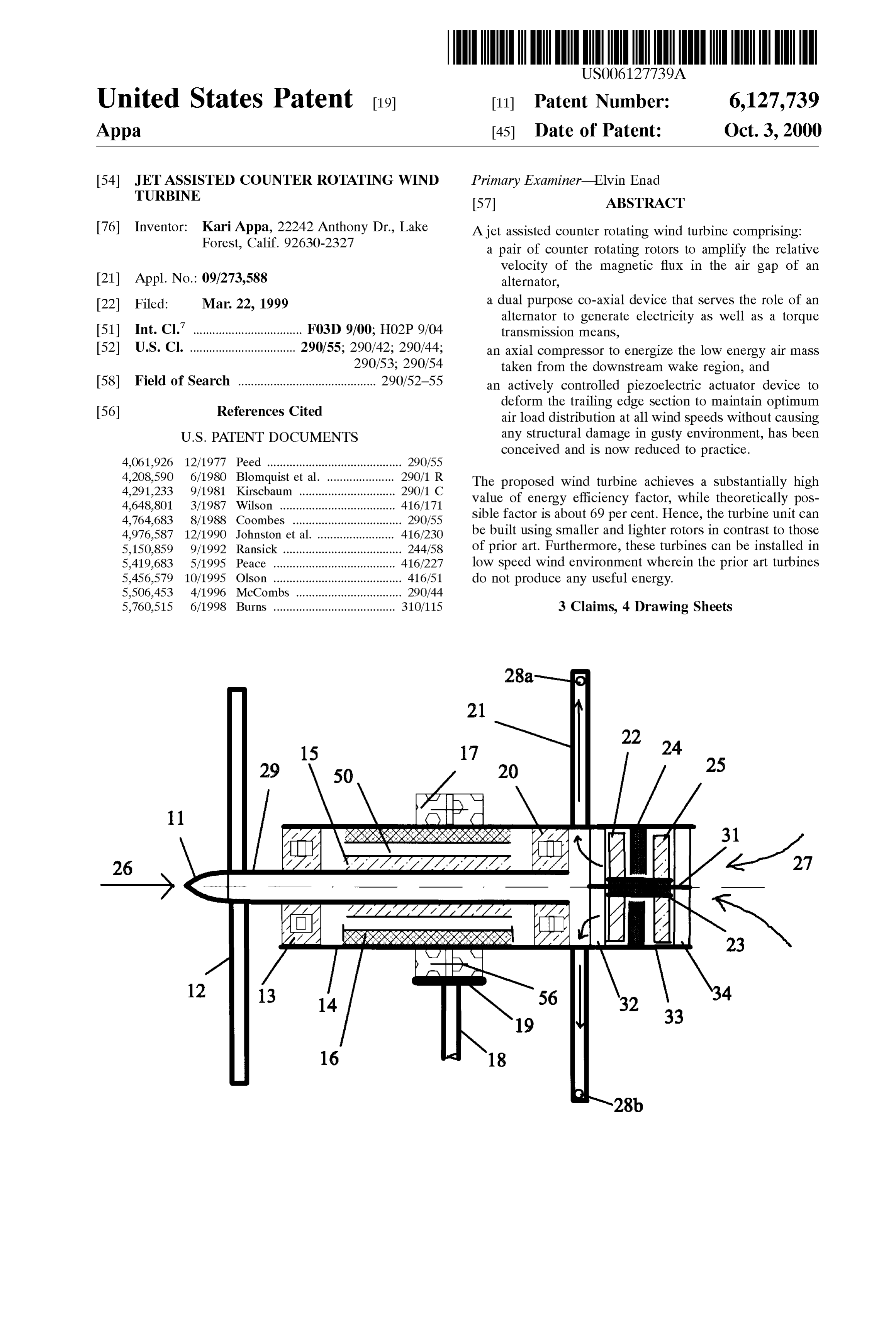
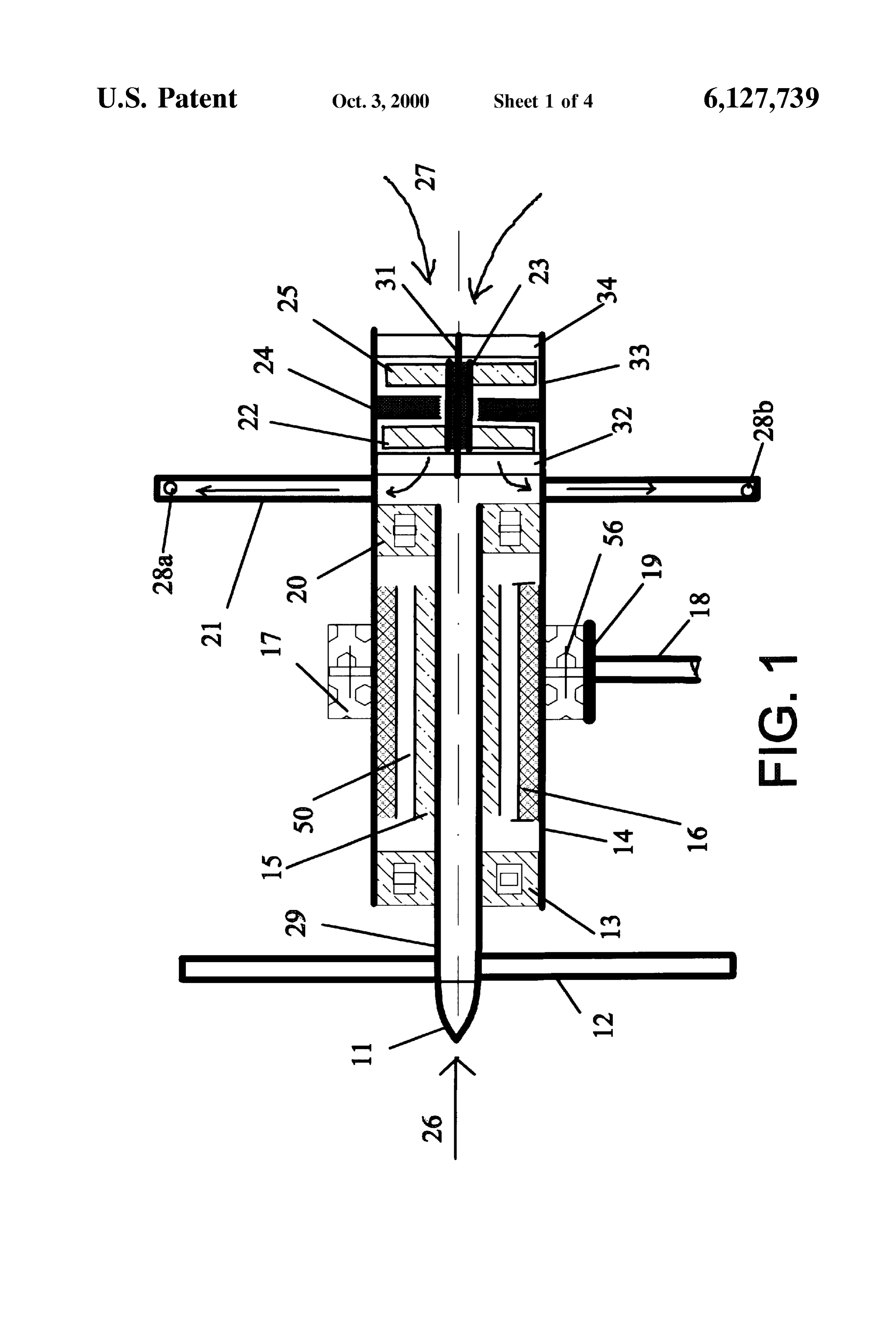
FIG. 1 shows the embodiment of a jet assisted wind 1. Preferred Embodiments of the Invention turbine assembly Drawings FIG. 2 shows a typical view of a rotor blade having an air FIG. 1, generally illustrates a typical embodiment of a jet passage between two spars
FIG. 3 shows the airfoil section with piezoelectric actua assisted a windward counter-rotating wind turbine comprising:
rotor 12 attached to an inner co-axial shaft 29, tor assisted deformable trailing edge a leeward rotor 21 attached to an outer co-axial shaft 14, FIG. 4 shows an overview of air jet assisted wind turbine 25 an axial air compressor 33 attached to Said Shaft 14, blade assembly a main bearing 17 Supporting the wind turbine System and FIG. 5 shows an over view of an air compressor assembly attached to a Swivel base 19,
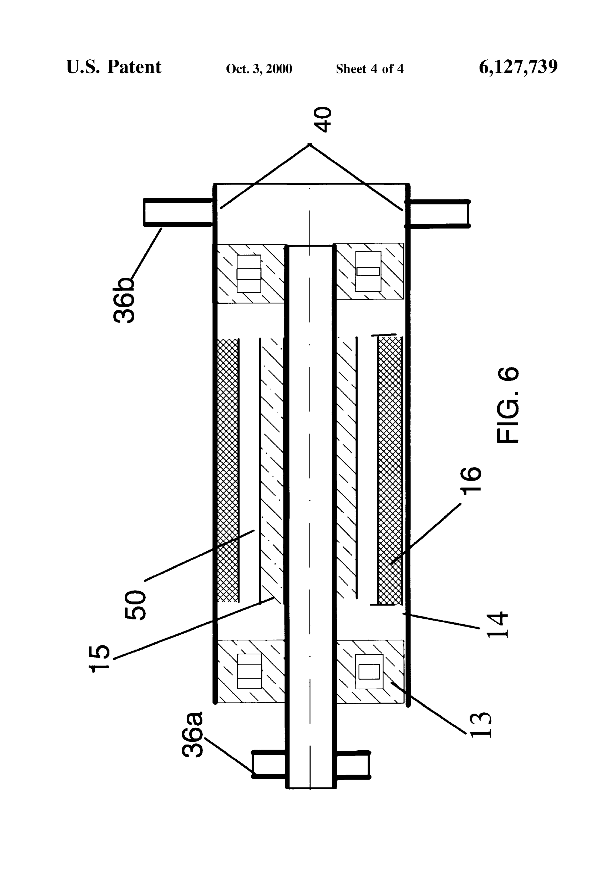
FIG. 6 shows the schematic of the co-axial shaft assembly a pair of slip ringS 56 enabling power transmission from the including a Solid State alternator alternator to an external load,
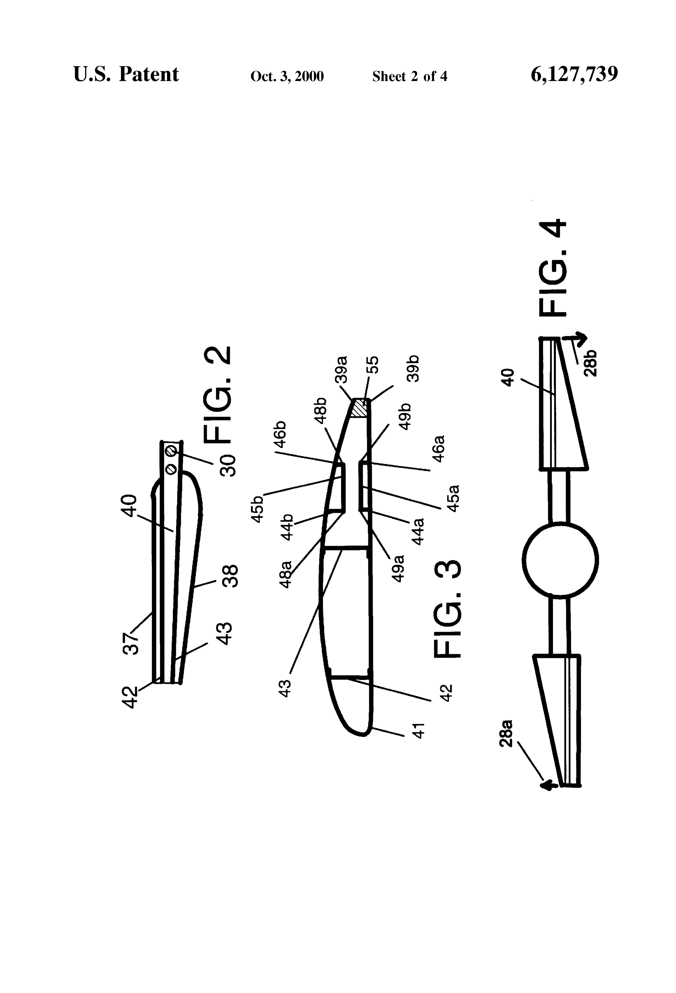
Reference Numerals a tubular mast 18 which in turn is attached to said Swiveling base 19, 11 nose cone A nose cone attached to said shaft 29 12 windward rotor blade FIG.2 shows a plan view of a rotor blade with its top skin 13 forward bearing between the co-axial shafts removed. The air passage 40 lies between the front spar 42 14 leeward rotor shaft 35 and the rear spar 43. The leading edge 38 and trailing edge 15 magnetic rotor 37 are straight, while the width of the blade decreases 16 wound armature linearly from 3/10 th radius to the tip. 17 leeward rotor shaft bearing attached to a Swiveling base FIG. 3 shows a schematic outline of an airfoil section, 18 mast generally of NASA LS(1)04XX series, taken at any radial 19 swiveling base attached to mast 40 Station of Said blade. The trailing edge comprises of a pair 20 rear bearing between the co-axial shafts of solid state (piezoelectric) actuators 45a, 45b attached to 21 leeward rotor blade the upper and lower skins respectively by means of upper 22 Second Stage compressor blade skin stringers 44b, 46b and lower skin stringers 44a, 46a. 23 axial compressor motor FIG. 4 shows an overview of an air jet assisted wind 24 guide vane 45 turbine blade assembly in which air jets 28a, 28b exit in 25 first stage compressor blade opposite directions at the leeward rotor blade tip. 26 inlet air stream line FIG. 5 shows a schematic outline of a two-stage axial 27 outlet air stream line entering the rotor blade compressor assembly comprising:
28a, b air jet outlet an electric motor 53, 29 windward rotor shaft 50 plurality of first Stage compressor blades 25 attached to the 30 tapered hubs by which blades and shafts are connected outer Surface of a motor case 53, 31 compressor axle plurality of guide Vanes 24 attached to the inner Surface of 32 forward Supporting bracket the compressor shell 33, 33 axial compressor (case) plurality of Second Stage compressor blades 22 attached to 34 rear Supporting bracket 55 the outer Surface of said motor case 53. 35 compressed air passage along leeward rotor blade, FIG. 6 shows the co-axial shaft assembly together with an 36 blade hub alternator. Two bearings 13, 20 are used to Support Said 36a,b tapered shanks shafts 14, 29 against radial and axial loads. Tapered tubular 37 leading edge of the rotor blade shanks 36a, 36b are welded to said shafts 14, 29 respec 38 trailing edge of the rotor blade 60 tively. Air passage holes 40 are permitted in said shaft 14. In 39a upper skin of the trailing edge addition certain fastening holes are drilled in Said shaft 14 to 39b lower skin of the trailing edge fasten Said compressor.
40 air passage 41 rotor blade skin 2. Preferred Embodiments of the Invention 42 front spar 65 Operations 43 rear spar A Schematic arrangement of a wind turbine according to 44a, b forward actuator attachment to skin the present invention is shown in FIG. 1. It has two rotors,
Page 8
S 6 a windward rotor 12 facing the upwind Stream, and a limit is seen to be about 69 per cent. Furthermore, this leeward rotor 21 placed behind said rotor 12. Each rotor System begins to produce useful energy at wind Speeds as comprises of two or three blades. Each blade is made of an low as 4 miles per hour. Whereas, the prior art require the airfoil section depicted in FIG. 3. The angle of incidence of cut-in wind Speed of 12 miles per hour or more. This is an each airfoil Section is Set in an appropriate orientation So that extremely important factor that influences additional advan the countervailing aerodynamic forces push the rotors to tages Such as reduced rotor diameter, reduced Structural Spin in opposite directions. The primary objective of this weight, increased Structural integrity, reduced noise, reduced arrangement is to increase the flux rate in the magnetic field wind farm acreage and ability to produce energy in low that would produce electricity even at wind Speeds as low as Speed wind environment.
4 miles an hour. 1O
For this reason said windward rotor 12 is directly coupled CONCLUSIONS, RAMIFICATIONS, AND to an inner shaft 29, while said leeward rotor is directly SCOPE coupled to an outer tubular Shaft 14. Permanent magnetic Accordingly, the reader will See that this invention pro strips are imbedded to the outer surface of said shaft 29. vides substantially highly efficient wind turbine. The effi Similarly, the armature windings 16 are attached to the inner
Surface of Said shaft 14. The co-axial shaft unit serves the 15 ciency enhancement arises from three factors namely the dual purpose, as an alternator to generate electricity and as counterrotor and rotating rotor System; the air jet assisted leeward an actively controlled trailing edge device. Since a device to transmit torque. the energy conversion efficiency is Substantially high, Said magnetic rotor 15 and said armature 16 rotate in Smaller diameter opposite directions to increase the relative speed in Said air integrity due to rotors can be used. This enhances Structural lower StreSS levels and also drastically gap 50. Hence, the electrical energy produced by this method is almost twice that from the prior art. A pair of Slip reduces its overall weight.
rings 56 is used to transfer electrical power from the Although the description above contains much specificity, armature to an external load. To ensure reduced drag forces these should not be construed as limiting the Scope of the on the Supporting Structure, a nose cone 11 is fixed to Said invention but as merely providing illustrations of Some of shaft 29. 25 the presently preferred embodiments of this invention. Vari FIG. 5 illustrates still another embodiment of the inven ous other embodiments and ramifications are possible within tion in which an axial compressor 33 is provided to pump a it's Scope.
mass of air taken from the wake region 26 behind Said Thus, the scope of the invention should be determined by leeward rotor 21. The compressed air 27 passes through said the appended claims and their legal equivalents, rather than air passage 40 in Said blades 21. AS the air moves along Said by the examples given.
blade further compression takes place due to the centrifugal I claim:
effect. The compressed air exists as countervailing jets 28a, 1. An assembly of jet assisted counter rotating wind 28b at the blade tip in the plane of the rotor. Said air jets 28a, turbine comprising:
28b produce a torque on Said leeward rotor to increase its (a) windward rotor having blade airfoils set to rotate in rotational Speed. Thus, the energy conversion efficiency is 35 clockwise direction and mounted on the inner Shaft of further amplified. a co-axial transmission device that includes a perma Said compressor 33 comprising: nent magnet rotor of an alternator, a Solid State motor including a magnetic rotor 52, an axle 31, (b) a leeward rotor having said airfoils set to rotate in an armature 54, bearings 51a, 51b, anti-clockwise direction and mounted on the Outer Shaft plurality of first Stage compressor blades 25, Second Stage 40 of Said co-axial device including a wound armature of compressor blades 22 welded to the outer Surface of Said Said alternator, armature shell 54, (c) a pair of radial and thrust load bearings fitted between said axle 31 firmly fixed to a front Supporting bracket 32, and Said co-axial shafts that Serve the dual purpose of Said a rear Supporting bracket 34, alternator and Said power transmission means, plurality of guide Vanes 24 fixed to the inner Surface of Said 45 (d) an axial air compressor that is fixed to the outer shell 33, is fasten to the inner Surface of said shaft 14. rotating Shaft and electrically linked to Said alternator, FIG. 3 illustrates still another embodiment of the inven and Supplies compressed air to Said leeward rotor, tion in which the trailing edges 37 of said blades 12, 21 are (e) a main bearing designed to withstand axial and radial provided with actively controlled piezoelectric actuators loads fitted on to Said outer Shaft, 45a, 45b. Said actuators are fixed to the inner Surface of skin 50 41 by means of stringers 44a, 44b, and 46a, 46b. The inner (f) a pair of slip rings attached to said outer shaft to surfaces of trailing edges 39a, 39b are fixed to a low-density transmit electrical energy from Said alternator to an non-metallic honeycomb 55 that provides damping against external load, vibration while permitting deferential movement of said (g) a Swivel platform to Support said main bearing includ edges 39a, 39b during deployment. Said actuators 45a, 45b 55 ing a pair of Slip ring brushes for energy transmission, either push or pull nodes 48a 48b and nodes 49a, 49b when (h) a tubular mast to Support said Swivel platform includ an electric potential applied acroSS two ends of Said actua ing the wind turbine unit, tors 45a, 45b respectively. The electrical input to said that provides Substantially enhanced energy production, actuators 45a, 45b is derived from said alternator device 15, lighter and durable Structure requiring minimal 16. The actuator mechanism working in pair enables the 60 maintenance, and an ability to produce electrical energy trailing edge section 37 to deform smoothly either upward or even in low Speed wind environment.
downward as the case may be. This device can be used to 2. A jet assisted counter rotating wind turbine Set forth in maintain optimum lift to drag ratio with varying wind claim 1 wherein Said axial compressor comprising: Speeds. This mechanism is also applicable to control the (a) an electric motor including plurality of two stage rotor Speed in gusty wind environment. 65 compressor blades and bearings, Thus, the twin rotor turbine system provides substantially (b) plurality of guide vanes fixed to a circular shell increased energy conversion efficiency, while the theoretical enclosing the compressor,
Page 9
(c) an inlet opening facing down stream wake region, leeward blades receiving electrical input Signal propor that provides a countervailing air jets using compressed air tional to the wind Speed, taken from the downwind wake region to enhance the (b) upper and lower trailing edge Surfaces which deform aerodynamic efficiency of the leeward rotor. under a pair of actively controlled actuator forces, 3. A jet assisted counter rotating wind turbine set forth in 5 provides a means to maintain the optimal Value of lift to drag claim 1 wherein, an actively controlled piezoelectric actua- ratio at all wind speeds so that said wind turbine delivers tion device comprising: maximum power output avoiding catastrophic structural (a) plurality of pair of piezoelectric actuators fixed to the damages in gusty wind environment. inner Surface of the skin near the trailing edge of Said k . . . .
Provenance
- Collection
- Cited prior art
- Original PDF
- patentimages.storage.googleapis.com →
- Filed
- 1999-03-22
- Pages
- 9
- Method
- pdftotext (the PDF's own text layer) + pdftoppm 300dpi page scans
- Source
- Google Patents bibliographic record
- Granted
- 2000-10-03
- Inventors
- Kari Appa
- Transcribed from
- patentimages.storage.googleapis.com →