patent · US3724861
New trapped bushing seal
3 April 1973
Page 1 — bibliographic record
United States Patent (19) 11 3,724,861 Lesiecki (45) Apr. 3, 1973
54 NEW TRAPPED BUSHING SEAL
(75) Inventor: Gerald
Lesiecki, Greendale, wis. Primary Examiner-Houston S. Bell, Jr.
Attorney-John P. Hines, Robert B. Benson and
Charles L. Schwab 73) Assignee: Allis-Chalmers Manufacturing Com pany, Milwaukee, Wis. 57 ABSTRACT 22 Filed: Oct. 27, 1970 A rotary shaft seal is provided with a sealing fluid to 21 Appl. No.: 84,296 seal a process fluid. The sealing fluid is admitted at a pressure just slightly higher than the pressure of the 52 U.S. Cl 277/25, 277/32, 277/68 process fluid to provide a seal when the shaft is sta 88 a a & a a assis & so 8 s A 277 170 277 | tionary and means are provided in the seal to increase (51 int. Cl. .............................................. is 1516
this pressure as a function of rotation, with centrifugal force, to a sufficiently higher pressure than that of the 277/28, 32, 67, 68,70,135, 14, 53 process fluid pressure to prevent entrainment of the process fluid within the sealing fluid. A stable sealing 56 References Cited fluid pressure decreasing means is provided in the seal which is also a function of rotation and which
UNITED STATES PATENTS decreases the sealing fluid pressure with centrifugal 2,573,425 10, 1951 Fletcher, Jr............................ 277/13 force from the pressure in the high pressure area to 3,062,554. 1 1/1962 McGahan et al...................277.125 X the pressure of the process fluid at the process fluid 3,122,374 2/1964 McGahan............................... 277127 sealing fluid interface. 3,127,181 3/1964 Crego et al...............................277.13 1,558,630 10/1925 Reed .................................. 277/28 X 4 Claims, 1 Drawing Figure
/. A?
1. O 2/
Page 2
Drawing sheet — no readable text.

Page 3
NEW TRAPPED BUSHING SEAL 1964, and assigned to the same assignee as this inven CROSS REFERENCE TO RELATED PATENT tion. While that seal has proven quite satisfactory, APPLICATION there is a considerable loss of sealing liquid while the machine is shutdown and prior to the time the machine
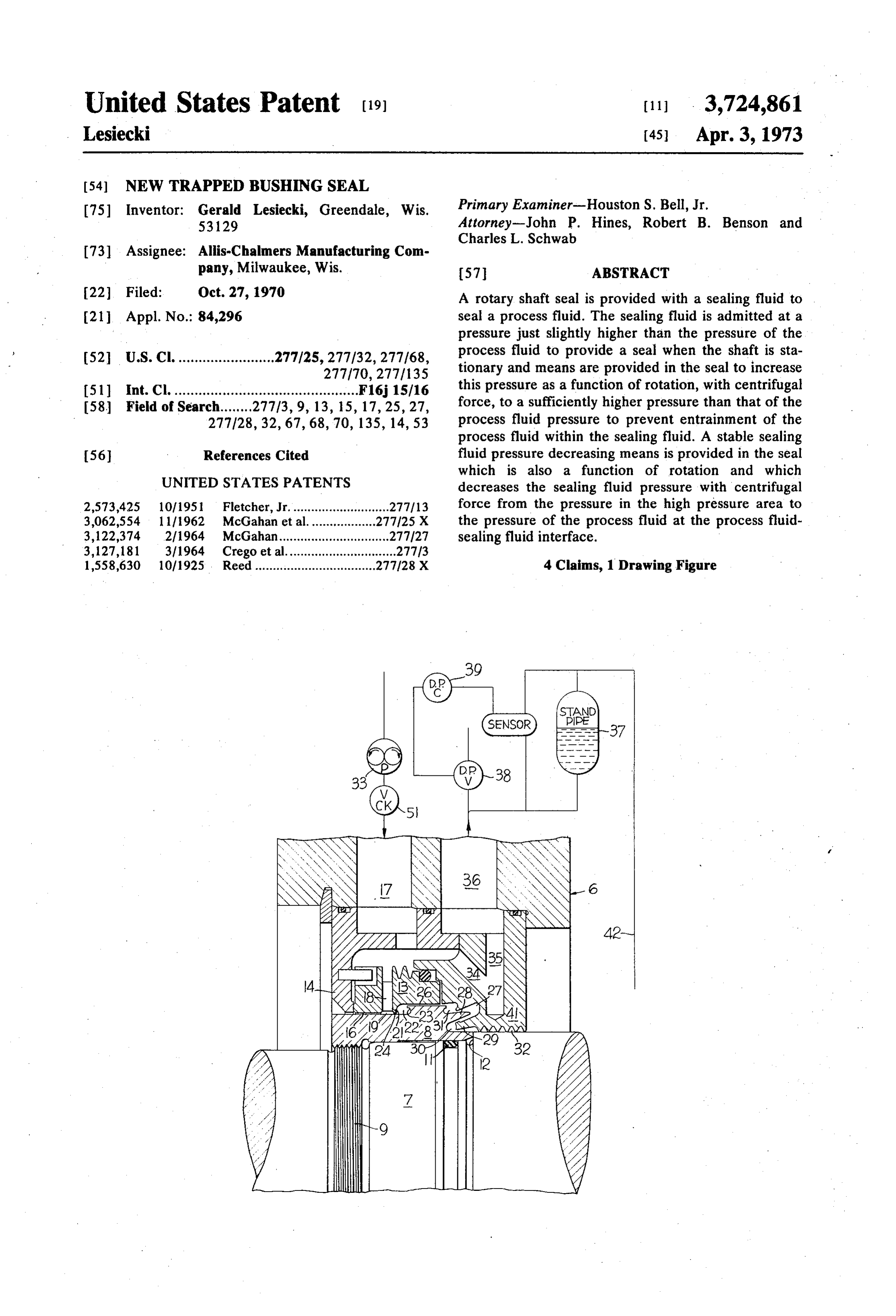
This invention pertains to a seal for fluid processing 5 reaches a certain percent of operating speed. rotating machinery which is also the subject of my It is the general object of this invention to provide a copending United States patent application entitled pumping type liquid film seal wherein the loss of sealing "Automatic Shutdown Seal,' Ser. No. 84,297 filed liquid during shutdown and while the machine is concurrently with this application. operating at less than normal speed is kept at a As the use of rotating machinery has expanded and O minimum.
the temperatures and pressures of the process fluids A further object of the subject invention is to provide have increased, the ever present problem of providing a a limited leakage shaft seal wherein the sealing liquid is seal between a rotating shaft and a stationary housing provided at a pressure only slightly higher than the has become more complex. A particularly difficult 15 process gas and means are provided within the seal to situation arises when it is required to seal a caustic or increase this pressure sufficiently to overcome entrain explosive gas. Since in this type of situation it is neces ment of the process gas into the sealing liquid. sary to insure a complete sealing of the gas, liquid seals An additional object of the subject invention is to are quite frequently used. For ease of explanation, this provide a seal of the hereinbefore described type with a description will refer to the process fluid as a gas and 20 refined sealing fluid pressure balancing means while the sealing fluid as a liquid. However, it should be un the machine is operating above 50 percent of normal derstood that the invention disclosed may be used in operation speed to substantially inhibit leakage of the other applications so long as the sealing fluid has a sealing liquid toward the process gas. greater density than the process fluid. These and other objects of the subject invention will There are three basic types of seals which will be 25 become more fully apparent as the following descrip referred to in this description. A mechanical seal as tion is read in light of the attached drawing which herein used refers to a seal wherein there is actual shows a cross sectional view of a seal constructed in ac physical contact between the rotating and stationary cordance with the invention.
portions of the seal. A liquid film seal as used herein Referring to the drawing a machine casing generally refers to a seal wherein a pair of bushings or a dual 30 designated 6 has an opening therethrough in which is bushing is buffered with a sealing liquid at a positive received a rotatable shaft 7. In this description, the left pressure above the process gas. A pumping type liquid hand end of the machine casing would be exposed to film seal as used herein refers to a seal wherein a liquid atmosphere and the right-hand end of the machine cas film type seal mentioned above is backed up with a ing would be connected to the rest of the rotating pumping device which inhibits the flow of sealing liquid 35 machine containing pressurized gas to be sealed. A towards the process gas during operation.
Each of these three different types of seals has in sleeveshaft 7 element or impeller 8 is rigidly connected to the in any conventional manner for rotation herent drawbacks. The obvious drawback of the mechanical seal is due to the physical contact between therewith. As herein shown for purposes of illustration, the rotating and stationary portions of the seal which 40 the shaft is provided with a threaded portion 9 onto results in wearing of these portions and ultimate failure; which ring 11 the impeller 8 is threaded. A conventional O may be provided between the shaft and the im the possibility of catastrophic failure always exists.
However, it does have the inherent quality of being a peller 8 to insure a seal therebetween. A locating positive seal during static conditions without a sealing shoulder 12 may be provided on the shaft to insure fluid. 45 proper axial location of the impeller 8. The liquid film seal, although not subject to the wear A stepped dual bushing 13 is positioned about the ing drawbacks of the mechanical seal, is only effective impeller 8 in radial clearance therewith of the mag while the sealing fluid is provided. The liquid film seal nitude commonly used in journal bearings. This has a high loss of sealing fluid toward the process gas stepped bushing may be constructed as a separate ele unless the clearances between the shaft and bushing are 50 ment as shown herein so that it will float with the shaft kept very small, less than 1 mil clearance per inch of 7 and impeller 8. One end portion of the stepped bush shaft diameter, and/or the sealing fluid pressure over ing 13 is in intimate contact with an end wall 14 of the the process gas is low. Therefore, the liquid film seal is outer seal housing to provide secondary sealing of the vulnerable to sudden temperature change which often sealing liquid from the atmosphere. The impeller 8 and results in failure and/or entrainment of the process gas 55 stepped bushing 13 define annular restricted fluid into the sealing liquid in the clearance area which passages 16 and 26 which are open to the atmosphere results in small quantities of the gas escaping to at and pressurized gas, respectively.
mosphere. This entrainment and its causes will be ex A sealing liquid inlet passage 17 is provided in the plained more fully later in the description. machine casing 6. The inlet passage 17 is in liquid com In the pumping type liquid film seal, the sealing 60 munication with a passageway 18 through the stepped liquid is always maintained at a substantial pressure bushing 13. The passageway 18 communicates with an above the process gas pressure to prevent entrainment annular inlet chamber 19 located about the impeller 8 of process gas in the sealing liquid so complete sealing and defined by walls of the stepped bushing 13. The of the process gas can be assured with a low loss of seal inlet chamber 19 is in liquid communication with one ing fluid towards the process gas at operating speed 65 end of the restricted fluid passage 16. comparable to that of the mechanical seal. Such a seal An annular ridge 21 on an interior surface of the is disclosed in U.S. Pat. No. 3,127,181, issued Mar. 31, stepped bushing 13 forms one wall of the inlet chamber
Page 4
19 and also one wall of a pumping chamber 22. This ever, it has been found that if too small a pressure dif pumping chamber 22 is defined by the ridge 21 and the ferential is maintained, gas becomes entrained in the stepped bushing 13 and a shoulder 23 on the impeller sealing liquid during operation and will find its way to 8. The interior annular edge of the ridge 21 defines an atmosphere. This entrainment is due to differential annular restricted port 24 connecting the inlet chamber pressure patterns that are set up in the area of the 19 with the pumping chamber 22. Since this port 24 has transfer passage 26. These differential pressure pat a much smaller axial surface than the restricted fluid terns are caused by conventional journal bearing action passages 16 or 26, it offers less resistance to liquid flow between the impeller 8 and stepped bushing 13. As the than the restricted fluid passage. impeller 8 rotates, it squeezes the sealing liquid against Annular restricted fluid passage 26 also serves as a 10 the bushing 13 causing high and low pressure areas transfer fluid passage. This transfer passage is at a which vary in intensity depending on the eccentricity greater radius than the port 24 and the restricted fluid between and the relative roundness of the impeller 8 passage 16 due to the shoulder 23 provided on the im and stepped bushing 13. These pressure areas may peller 8. The transfer fluid passage is in fluid communi 5 rotate or assume some relatively fixed position in the cation with the pumping chamber 22 and with a radial transfer passage 26. If the liquid pressure in these low passage generally designated 27. The transfer passage pressure areas is below the gas pressure, the gas will restricts the leakage of sealing liquid toward the enter the low pressure areas and find its way to at process gas during static conditions or part speed mosphere. the low
In order to insure that the gas does not enter pressure areas, the sealing liquid pressure has operation. The radial passage 27 is defined by one end 20 to be sufficiently high so that the pressure of the liquid of the impeller 8 and a nonrotational portion of the seal in the low pressure areas is greater than the pressure of housing or stator 41. the gas.
The radial passage 27 is composed of one or more With this larger pressure differential, we again have radially spaced substantially axially disposed fingers 28 on the impeller 8. Complementary radially spaced an 25 the problem of an excessive amount of sealing liquid nular substantially axially disposed fingers 29 are pro flowing towards the gas. This problem was overcome in vided on the nonrotational stator 41. These interleaved the previously mentioned U.S. Pat. No. 3,127,181 with a similar configuration of radial passage 27 to insure ef fingers 28 and 29 define an annular swirl chamber 30. ficient back pressure pumping. In that patent, spoilers It should be understood that although one annular swirl 30 were provided to insure inefficient forward pressure chamber 30 is herein shown, two or more such cham pumping so that the net pumping was backward to just bers may be required on certain applications. balance the pressure in the inlet chamber 19 and keep The radially outer end of the radial passage 27 is in the liquid-gas interface within radial chambers 30. fluid communication with the annular transfer passage 26 through a chamber 31. The radially inner end of the 35 With such an arrangement as disclosed in the prior radial passage 27 is in fluid communication with what is sured at all patent, mentioned complete sealing of the gas is as times utilizing a high differential pressure shown herein as a labyrinth-type passageway 32. This on the order of 10 psi. Furthermore, since the effective labyrinth-type passageway is defined by the shaft 7 and pressure differential across the transfer passage 26 is the stator 41. The opposite end of the labyrinth-type zero, only a minimal amount of sealing liquid will flow passageway 32 is in fluid communication with the 40 into the process gas while the machine is operating. process gas side of the seal. However, with this high pressure differential, the A pump 33 is provided to supply the pressurized seal amount of sealing liquid flowing toward the gas during ing liquid through a check valve 51 to the inlet passage low speed and static 17. Cooling passages generally designated 34 and 35 intolerable. In the sealoperation of this is in some applications invention the pressure of connect the inlet passage 17 with a discharge passage 45 the sealing liquid during low speed and static operation 36. This discharge passage 36 is in communication with has been substantially reduced. It has been established a stand pipe 37 and also with the system sump (not empirically that in order to maintain sufficient sealing shown) through the differential pressure control valve liquid pressure in the low pressure areas caused by the 38. The stand pipe 37 is in fluid communication with previously described journal bearing action, the sealing the process fluid by means of conduit 42. Means may 50 liquid must be maintained at a pressure which is at a be provided in the form of a differential pressure con nominal 10 psi higher than the gas pressure at trol (or level control) 39 to insure sufficient liquid level peripheral speeds in the normal operating range of the in the stand pipe. machine. The sealing liquid pressure entering the radial It is now necessary to analyze how this new seal passage 17 of this new trapped bushing seal is a operates to understand how it distinguishes over the 55 nominal 2 psi higher than the gas pressure. The sealing prior art. If the gas is to be sealed from the atmosphere, liquid flows to pumping chamber 22 where due to the the pressure of the sealing liquid entering the chamber centrifugal effect of the shoulder 23, its pressure is 19 must be at a greater pressure than the gas pressure. raised to approximately 10 pounds higher than the gas If the sealing liquid pressure is too high, an excessive 60 pressure during normal operation. Because of the ef amount of the liquid will flow toward the process gas fect of centrifugal force in the pumping chamber, the where it may become contaminated, and an expensive mean pressure in the transfer passage 26 is also 10 separation procedure may be necessary to remove the pounds higher than the gas pressure, and this pressure gas from the sealing liquid or the liquid may have to be forces the liquid to move down into chambers 31 and discarded. Therefore, attempts have been made to 65 30. Since the journal bearing action occurs in the maintain the liquid pressure only slightly higher than transfer passage 26, no entrainment of the gas into the the gas pressure so an excessive amount of the sealing liquid results because of this 10 psi pressure differential liquid does not become contaminated by the gas. How of the sealing liquid above the process gas.
Page 5
The pumping action due to centrifugal force of the cient to block the flow of said high pressure fluid when rotating liquid in chamber 31 creates the back pressure said shaft is not rotating; walls defining a restricted to counteract the forward pressure of chamber 22. Suf fluid passage having one end in fluid communication ficient chambers 30, usually one, are provided so that with said low pressure area and the other end in fluid the pumping action due to centrifugal force of the communication with said inlet passage; a pumping rotating liquid in chamber 22 creates adequate back chamber defined by a rotational wall and an adjacent pressure to balance the remaining forward pressure stationary wall; means connecting said pumping from chamber 22, if any, and the pressure above chamber to said inlet passage; a radial fluid passage process gas of the sealing liquid in chamber 19. This in defined by a rotational wall and a stationary wall in sures that an interface of gas and liquid exists in 10 fluid communication with said high pressure area, said chamber 30. Therefore, little or no liquid seeps towards rotational wall exerting a backward pressure on said the gas during normal operation because the effective sealing fluid in opposition to the pressure created in differential pressure towards the gas in transfer passage said pumping chamber; and a transfer passage defined 26 equals zero. Furthermore, since the pressure of the by a rotating surface and a stationary surface connect sealing liquid in the transfer passage 26 is at a sufficient 15 ing said pumping chamber in fluid communication with mean pressure differential above the gas, as for in said radial passage at a point spaced radially outwardly stance 10 psi, the lowest pressure due to the journal from said radial passage connection to said high pres bearing action at either end of this passage will always sure area, the fluid in said transfer passage being ex be greater than the gas pressure; therefore, entrain posed to high and low pressure gradients due to journal ment of the gas into the sealing liquid will not occur. 20 bearing action, said pumping chamber being con However, contrary to the seal disclosed in the above structed and arranged to raise said sealing fluid pres identified patent, the pressure of the sealing liquid at sure so that the lowest journal bearing type pressure in the entrance to transfer passage 26 of this seal said transfer passage extremity is above the pressure of decreases as the machine slows down. When the said high pressure fluid area. machine is completely stopped, the sealing liquid pres 25 2. The combination set forth in claim 1 wherein the sure is only on the order of 2 psi above the gas pressure backyward pressure created in said radial passage is as compared to the 10 psi in the previous seal. It can equal to the pressure created in said pumping chainber thus be seen that with this seal only one-fifth of that plus the pressure of said sealing fluid. 3. The combination set forth in claim 1 wherein said quantity of sealing liquid used in the previous seal will flow toward the process gas during low speed and static 30 transfer passage is in fluid communication with both said pumping chamber and said radial passage during operation.
The embodiments of the invention in which an exclu all stages of operation and shutdown of said sealing
sive property or privilege is claimed are defined as fol 4. The combination set forth in claim 1 wherein said lows:
1. In combination with a housing surrounding a rotat 35 transfer passage is a restricted fluid passage disposed ing shaft, sealing means for sealing a high pressure fluid substantially parallel to the axis of said shaft and radi area from a low pressure fluid area comprising: a seal ally spaced therefrom a distance substantially equal to ing fluid inlet passage in said housing; a sealing fluid the spacing of the radially outer ends of said pumping source in communication with said passage supplying chamber and radial passage from said shaft. pressurized fluid thereto at a pressure only just suffi 40 xk k sk k sk
Provenance
- Collection
- Cited prior art
- Original PDF
- patentimages.storage.googleapis.com →
- Filed
- 1970-10-27
- Pages
- 5
- Method
- pdftotext (the PDF's own text layer) + pdftoppm 300dpi page scans
- Source
- Google Patents bibliographic record
- Granted
- 1973-04-03
- Inventors
- G Lesiecki; Allis Chalmers Corp
- Transcribed from
- patentimages.storage.googleapis.com →