patent · US6365994
Motor-operated flow control valve and exhaust gas recirculation control valve for internal combustion engine
2 April 2002
Page 1 — bibliographic record
(12) United States Patent (10) Patent No.: US 6,365,994 B1 Watanabe et al. (45) Date of Patent: Apr. 2, 2002
(54) MOTOR-OPERATED FLOW CONTROL 4,397.275 A 8/1983 Itoh et al. ................... 123/339 WALVE AND EXHAUST GAS 4,414.942 A 11/1983 Itoh et al.................. 123/339 RECIRCULATION CONTROL VALVE FOR E.
INTERNAL COMBUSTION ENGINE 5,058,625 A * 10/1991 Kaiser et al. .......... 137/624.15 O O 4 - 1 - 17 . . 5,099,161. A * 3/1992 Wolfbauer, III .............. 310/80 (75) Inventors: Youichi Watanabe, Hitachinaka; 5,184,593 A 2/1993 Kobayashi .................. 123/339 Yasuyuki Nakano, Naka-gun; 5,298,822 A 3/1994 Bosman et al. ........... 310/49 R Masayuki Suganami, Kzunori Irifune, 5,451824. A * 9/1995 Sieber et al. ................. 310/80 both of Hitachinaka, all of (JP) 5,501,201. A * 3/1996 Miyoshi et al......... 123/568.24
(73) Assignees: Hitachi, Ltd., Tokyo; Hitachi Car 5,769,390 A * 6/1998 Ando .................... 251/129.11 Engineering Co., Ltd., Hitachinaka, both of (JP) FOREIGN PATENT DOCUMENTS
(*) Notice: Subject to any disclaimer, the term of this JP T-190227 7/1995 patent is extended or adjusted under 35
U.S.C. 154(b) by 0 days. * cited by examiner
Primary Examiner Elvin Enad (21) Appl. No.: 09/733,989 (74) Attorney, Agent, or Firm-Crowell & Moring LLP (22) Filed: Dec. 12, 2000 (57) ABSTRACT Related U.S. Application Data Disclosed is a motor-operated flow control valve for internal combustion engines which has a longer useful life and does (63) Continuation of application No. 09/431,925, filed on Nov. 2, not cause a drop of torque generated by a motor at the 1999, which is a continuation of application No. 08/897,307, Start-up. A rotor Shaft (9) is reciprocated with rotating filed on Jul. 21, 1997, now Pat. No. 6,089,536. motion of a motor (32), whereupon a valve head (2.a) is (30) Foreign Application Priority Data moved to open and close an orifice for control of a flow rate. Jul. 19, 1996 (JP) ............................................. 8-190525
Specific frequency of a rotor unit (33) of the motor (32) is
Set to be higher than the Secondary vibration frequency of (51) Int. Cl. ................................................ HO2K 37/00 rotation of a 4-cycle internal combustion engine. The rotor (52) U.S. Cl. ....................................... 310/49 R; 310/90 unit (33) comprises an integral magnet (25), a single ball (58) Field of Search ................................. 310/49 R, 80; bearing (27) and a resin-made magnet holder (26) for 123/339 Supporting these two members, the magnet, the ball bearing and the magnet holder being formed into an integral Struc (56) References Cited ture. The rotor unit is Supported Such that an outer race (27c) of the ball bearing (27) is held at its one end against an inner
4,378,767 A 4/1983 Kobashi et al. ............. 123/339 applied to the other end of the outer race (27c). 4,378,768 A 4/1983 Itoh et al. ................... 123/339 4,381,747 A 5/1983 Kobayashi et al. ......... 123/339 1 Claim, 4 Drawing Sheets
PREOAD PREOAD
Page 2
Drawing sheet — no readable text.
Page 3
Drawing sheet — no readable text.
Page 4
Drawing sheet — no readable text.
Page 5
Drawing sheet — no readable text.
Page 6
MOTOR-OPERATED FLOW CONTROL the Secondary vibration frequency of rotation of a 4cycle WALVE AND EXHAUST GAS internal combustion engine. With this feature, when applied RECIRCULATION CONTROL VALVE FOR to any of internal combustion engines having four, Six and INTERNAL COMBUSTION ENGINE eight cylinders, the motor-operated flow control valve will not give rise to a resonance phenomenon and therefore has
This application is a continuation of application Ser. No. a longer useful life.
09/431,925, filed Nov. 2, 1999 which is a file wrapper In the above motor-operated flow control valve, continuation of Ser. No. 08/897,307, filed Jul. 21, 1997 now preferably, the rotor unit comprises an integral magnet, a U.S. Pat. No. 6,089,536. Single ball bearing and a resin-made magnet holder for Supporting the magnet and the ball bearing, the magnet, the
BACKGROUND OF THE INVENTION ball bearing and the magnet holder being formed into an 1. Field of the Invention integral structure. With this feature, the weight of the rotor The present invention relates to a motor-operated flow unit can be So reduced as to make the Specific frequency of control valve Suitable for use in internal combustion 15 the rotor unit have a value not resonating with engine vibration.
engines, and more particularly to an exhaust gas recircula tion control valve for internal combustion engines. Further, to Solve the above objects, according to the 2. Description of the Related Art present invention, in a motor-operated flow control valve comprising a rotor Shaft reciprocating with rotating motion
Conventional motor-operated flow control valves have of a motor, and a valve head movable to open and close an Such a known Structure that a rotor unit of a motor for driving a valve is rotatably Supported by a pair of ball orifice with the reciprocating motion of the rotor Shaft, a rotor unit of the motor comprises an integral magnet, a bearings disposed in upper and lower portions of the rotor Single ball bearing and a magnet holder for Supporting the unit. magnet and the ball bearing, the ball bearing having an outer Those conventional motor-operated flow control valves race held fixed under a preload. With this feature, frictional are disclosed in, for example, U.S. Pat. Nos. 4,432,318, 25 torque occurred upon Starting the rotor unit to rotate is 4,381,747, 4,378,767, 4,378,768, 4.414,942, 4,397.275 and reduced and torque required for the motor to produce at the 5,184,593, JP-A-7-190227 and 7-190226, etc. Start-up is made Smaller.
SUMMARY OF THE INVENTION BRIEF DESCRIPTION OF THE DRAWINGS
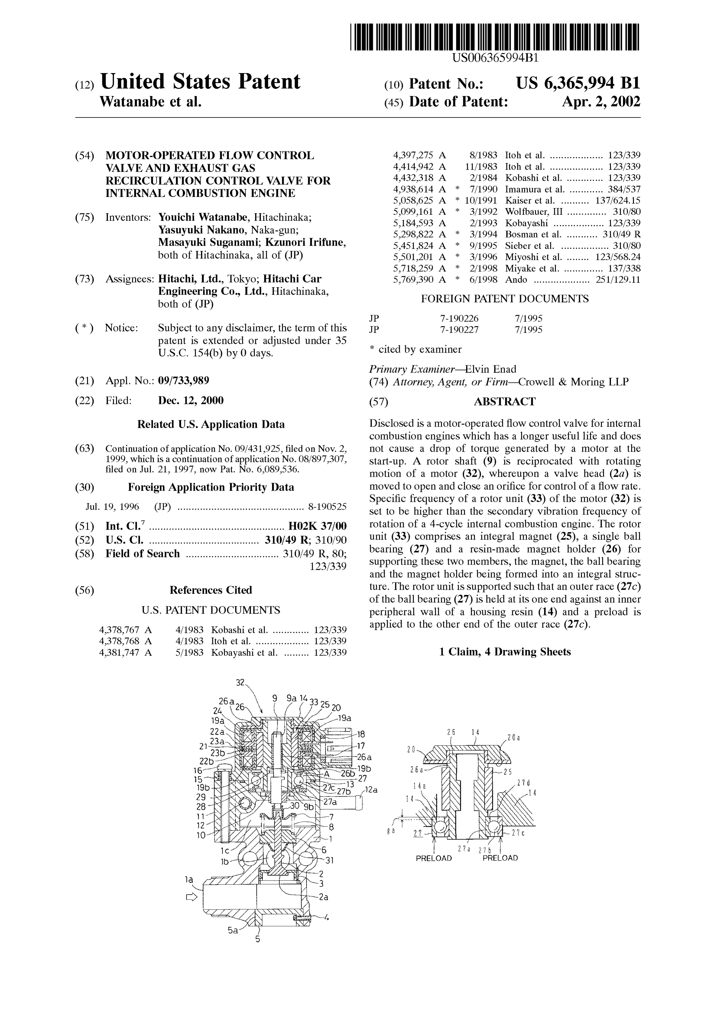
In the conventional motor-operated flow control valves, FIG. 1 is a vertical Sectional view of a push-opened, because the rotor unit of the motor is rotatably Supported by motor-operated flow control valve for internal combustion two ball bearings disposed in upper and lower portions of the engines according to one embodiment of the present inven rotor unit, there inevitably occurs relative wobbling between tion.
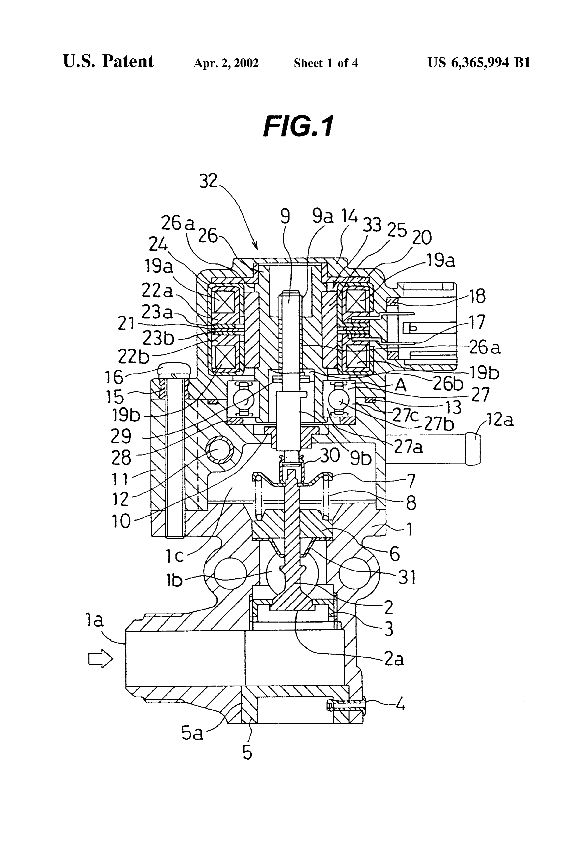
inner and outer races of each of the ball bearings. When used 35 FIG. 2 is a Schematic view showing a construction of a in internal combustion engines, therefore, Such a motor device for measuring the resonance frequency of a rotor unit operated flow control valve tends to resonate with rotative
Vibration of the internal combustion engine, resulting in a of ing a motor in the motor-operated flow control valve accord to one embodiment of the present invention.
problem that the useful life of the valve itself and a device including the valve is shortened. FIG. 3 is a graph showing a measured result of the To lessen the relative wobbling between the inner and resonance frequency of the rotor unit of the motor in the
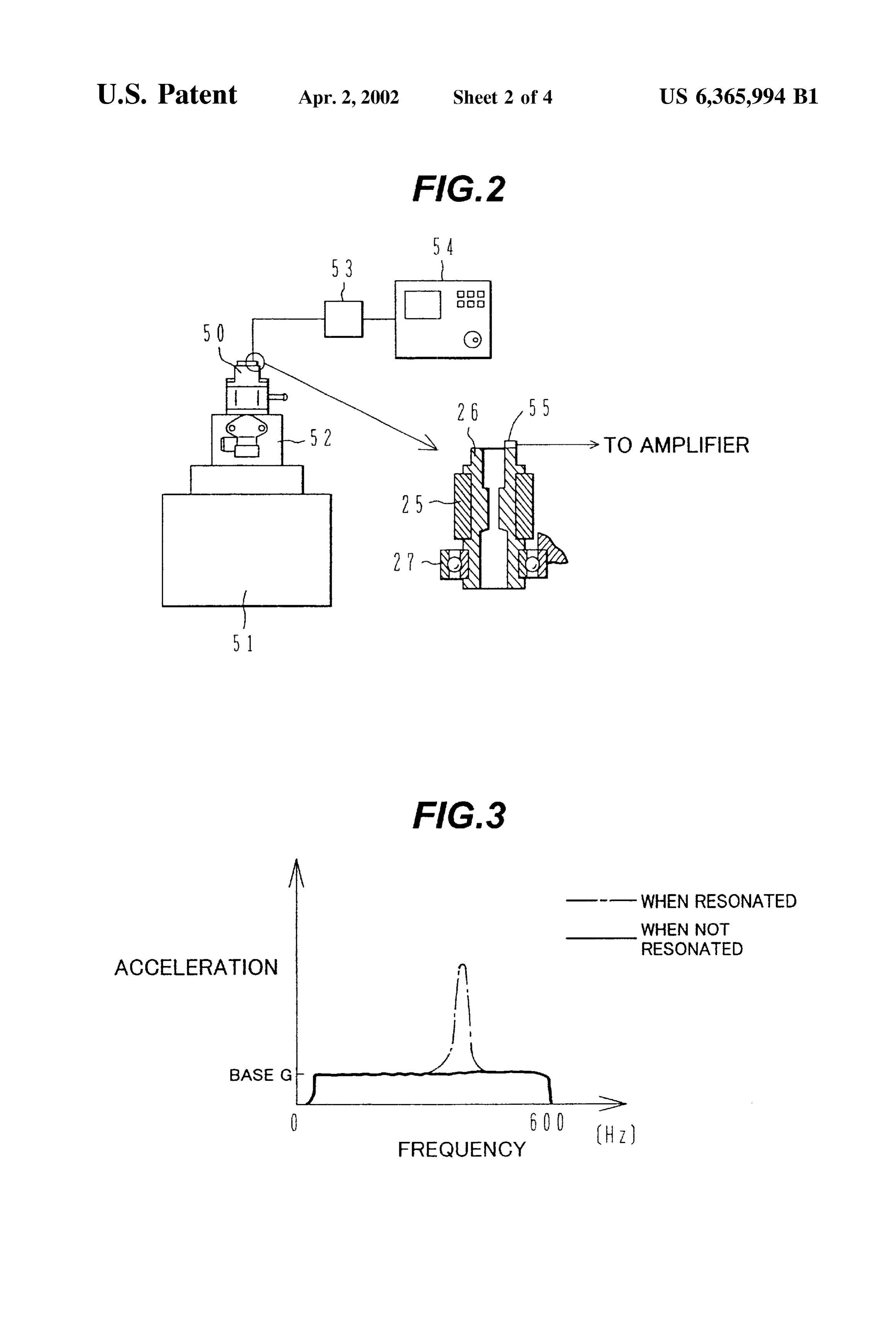
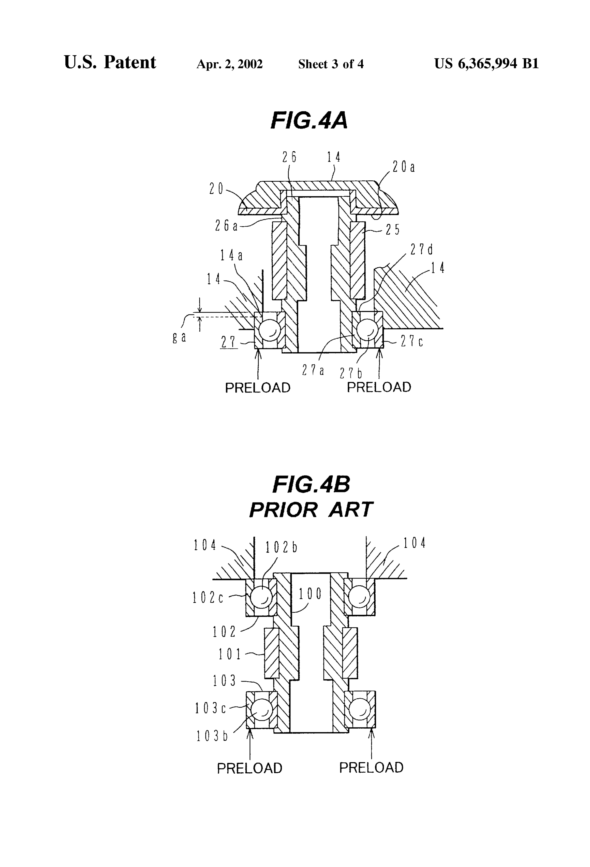
outer races, there is also known a structure that the rotor unit motor-operated flow control valve according to one embodi is Supported by two bearings under a State where a preload ment of the present invention. is applied to press the rotor unit in one direction. FIG. 4A is a view for explaining a preload applied to a ball Specifically, for example, an outer race of one ball bearing 45 bearing of the rotor unit of the motor in the motor-operated is Supported by a rigid body Such as a housing, and an outer flow control valve according to one embodiment of the race of the other ball bearing is pressed by a Spring Such as present invention, and a Spring washer or a coil Spring. With Such a structure, FIG. 4B is a similar view for explaining a preload applied however, because the preload generated by the Spring to a ball bearing in the prior art.
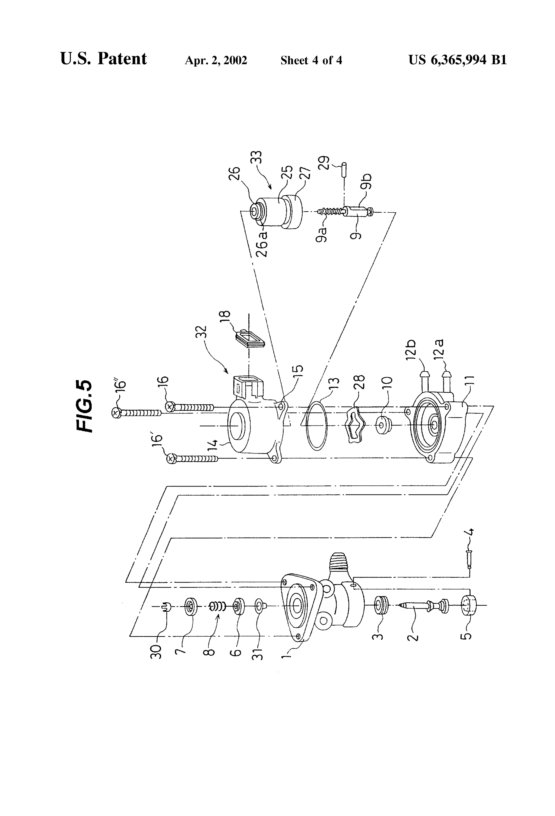
washer or the like is applied to balls of the ball bearing as 50 FIG. 5 is an exploded perspective view of parts of the well, frictional torque occurred upon Starting the rotor unit motor-operated flow control valve according to one embodi to rotate is increased. This results in another problem that the ment of the present invention.
motor is required to produce a larger torque at the Start-up.
DESCRIPTION OF THE PREFERRED
An object of the present invention is to provide a motor EMBODIMENT operated flow control valve for internal combustion engines 55 which is less affected by vibration and has a longer useful A motor-operated flow control valve for internal combus life. tion engines according to an embodiment of the present Another object of the present invention is to provide a invention will be described hereunder with reference to motor-operated flow control valve for internal combustion FIGS. 1 to 5.
engines which does not require a motor to produce a larger 60 FIG. 1 is a vertical Sectional view of a push-opened, torque at the Start-up. motor-operated flow control valve according to an embodi To achieve the above objects, according to the present ment of the present invention.
invention, in a motor-operated flow control valve compris The motor-operated flow control valve according to this ing a rotor shaft reciprocating with rotating motion of a embodiment is employed as an EGR (Exhaust Gas motor, and a valve head movable to open and close an orifice 65 Recirculation) valve for internal combustion engines. A with the reciprocating motion of the rotor shaft, Specific Valve body 1 defines an gas passage therein. Exhaust gas frequency of a rotor unit of the motor is Set to be higher than from an internal combustion engine flows into the valve
Page 7
body 1 through an inlet 1a and then flows out through an body 11 are positioned to have their axes coaxial with the outlet 1b for return to the intake pipe side of the internal axis of the ball bearing 27 as if those two members are one combustion engine. integral member.
An orifice member 3 is Screwed into the gas passage A hole 5a is bored in the valve body 1 to align with an between the inlet 1a and the outlet 1b. A valve shaft 2 having extension of the axis of the motor 32, allowing the valve a valve head 2a provided at one end extends through a shaft 2 to be inserted into the gas passage in the valve body central opening (valve seat) formed in the orifice member 3 1 for installation.
So that an orifice is opened and closed by the valve head 2a. The construction of the motor 32 will be described below. A gas seal 6 is fixedly press-fitted in the valve body 1 and The stator unit of the motor 32 comprises a coil 19a housed Serves to Seal off the exhaust gas flowing through the gas in a bobbin 22a and a coil 19b housed in a bobbin 22b. passage against leakage. The valve shaft 2 is slidably Magnetic fields are generated by Supplying electric currents Supported by the gas Seal 6. A dust cover 31 is attached to the coils 19a, 19b.
between the gas seal 6 and the valve body 1 to prevent A yoke for forming a magnetic path has a C-shape in foreign matters, Such as carbon and oil contained in the Vertical Section, and is made up of a yoke.24 nearly in the exhaust gas, from adhering to a gap between an outer 15 form of a hollow annulus cylinder and two disk-shaped circumferential Surface of the valve shaft 2 and the gas Seal yokes 23a, 23b. The bobbin 22a including the coil 19a is 6. disposed in a Space defined by the yoke 24 and the yoke 23a, A plate 7 is connected by caulking to an upper end of the while the bobbin 22b including the coil 19b is disposed in a valve shaft 2 through a joint 30. A spring 8 is interposed space defined by the yoke 24 and the yoke 23b. Between between the plate 7 and the gas seal 6 to bias the plate 7 both the yokes 23a and 23b, a center plate 21 is disposed upward. The valve shaft 2 joined to the plate 7 is thereby to not only position the upper and lower yokes 23a , 23b, urged upward, causing the valve head 2a to preSS against the but also prevent magnetic interference possibly caused valve seat of the orifice member 3. The valve head 2a is of between the upper and lower coils 19a, 19b. push-opened type that it opens the orifice when pushed Disposed above the yoke 24 is a metallic upper plate 25 downward. 25 which functions as a flat bearing for an upper portion of a
A body 11 and a motor 32 are both fixed to an upper magnet holder 26. Terminals 17 are electrically connected to portion of the valve body 1 by a set screw 16. A bushing 15 the coils 19a, 19b for supplying electric currents to the coils is inserted in a hole in which the set Screw 16 for the motor 19a, 19b. A sealing rubber 18 is attached around the termi 32 is inserted. The motor 32 is mounted in coaxial relation nals 17 to establish a watertight condition when connectors to the body 11. Between the motor 32 and the body 11, there are fitted into the terminals 17 for supply of electric currents. is interposed an O-ring 13 to block off the intrusion of water, The stator unit thus constructed is covered and fixed by the oil, etc. from the external. housing resin 14.
The body 11 serves as an intermediate member for joining The rotor unit 33 of the motor 32 comprises a magnet 25, the motor 32 and the valve body 1 to each other. Since the 35 the ball bearing 27, and a resin-made magnet holder 26 exhaust gas at high temperature flows through the gas Supporting the former two members, which are integrally passage in the valve body 1, the body 11 has a cooling formed by insert molding. PPS (polyphenylene sulfide resin) Structure to prevent the heat of the exhaust gas from being is used as a resin material of the magnet holder 26. Teflon is transmitted to the motor 32. Specifically, a cooling pipe 12 added to PPS to provide the resin material with higher is embedded inside the body 11 and cooling water is 40 slidability. Note that, in addition to PPS, PBT (polybutylene Supplied from a cooling pipe inlet 12a to flow through the terephtalate resin), PA (polyamide resin), etc. are also usable cooling pipe 12. A cooling pipe outlet 12b is located, as as the resin material. The magnet holder 26 has female shown in FIG. 5, near the cooling pipe inlet 12a in side threads 26.a formed in its inner circumferential Surface. A by-Side relation. The cooling water flows into the cooling Stopper 26b is integrally formed on the magnet holder 26 in pipe 12 through the inlet 12a, goes Substantially round the 45 a position inside the magnet holder 26 and below the female interior of the body 11, and then flows out of the outlet 12b. threads 26a, thereby restricting the rotation of a rotor shaft The cooling water contributes to more than cooling the 7 when the rotor shaft 7 reaches a maximum pull-up motor 32 alone. The heat transmitted from the exhaust gas position.
at high temperature may melt grease for a ball bearing 27 Here, Since the components of the rotor unit 33, i.e., the rotatably supporting a rotor unit 33 of the motor 32. If the 50 magnet 25, the ball bearing 27 and the magnet holder 26, are Viscosity of grease is lowered, the rotor rotation would be So integrally formed by Simultaneous molding, it is possible to fast as to cause an overshoot in opening and closing opera omit steps of bonding the magnet and preSS-fitting the ball tion of the valve head 2a. bearing, which have been essential in the prior art, and hence In this embodiment, the cooling water also cools the ball to reduce the number of Steps necessary for assembly. The bearing 27 So that the Viscosity of grease can be kept at a 55 Simultaneous molding can also improve coaxiality among necessary level. Further, a wave washer 28 is interposed the magnet 25, the ball bearing 27 and the magnet holder 26, between the ball bearing 27 and a portion of the body 11 and therefore can reduce a variation in torque generated by Supporting it to prevent the heat from the exhaust gas from the motor.
being directly transmitted to the ball bearing 27. On the The rotor unit 33 of the motor 32 is rotatably held within other hand, the cooling effected by the cooling water pro 60 the Stator unit of the motor 32. Specifically, an upper end of motes heat dissipation from the circumference of an outer the rotor unit 33 is rotatably supported by the upper plate 20 race of the ball bearing 27. as part of the Stator unit. In other words, an upper end portion An outer race 27c of the ball bearing 27 is held by being of the magnet holder 26 is rotatably Supported at its outer fitted astride between an inner peripheral wall of a Socket circumferential Surface by an inner circumferential Surface portion of the body 11 and an inner peripheral wall of a 65 of the upper plate 20. Also, a lower end of the rotor unit 33 Socket portion of a housing resin 14 constituting a Stator unit is rotatably supported by the ball bearing 27. The ball of the motor 32. With this structure, the motor. 32 and the bearing 27 as one component of the rotor unit 33 comprises
Page 8
S 6 an inner race 27a integrally fixed to the magnet holder 26, race 27c of the ball bearing 27 in the thrust direction serves balls 27b, and an outer race 27c. An upper end of the outer to not only produce but also adjust the preload. race 27.c is held against the inner peripheral wall of the The outer race 27c of the ball bearing 27 is loose-fitted at housing resin 14 of the motor 32, as indicated by arrow A in its outer circumference astride between the inner peripheral FIG. 1. Further, a lower end of the outer race 27.c is biased wall of the socket portion of the housing resin 14 of the toward the side of the motor 32 under a preload applied by motor 32 and the inner peripheral wall of the Socket portion a wave washer 28. The wave washer 28 is interposed of the body 11. Therefore, the outer race 27c of the ball between the outer race 27c of the ball bearing 27 and the bearing 27 is movable through a distance corresponding to body 11. the gap g, in the thrust direction without undergoing resis The rotor shaft 9 converts rotating motion of the motor 32 tance by the tightening force produced when the Screw 16 is into reciprocating motion So that the valve shaft 2 recipro fastened to the body 11.
cates. The rotor shaft 9 has male threads 9a formed in Whether the gap g, is to be left Somewhat or become Zero complementary relation to the female threads 26.a formed after the Screw 16 has been fastened, is Set case by case the magnet holder 26. The rotor shaft 9 extends through the depending on how much preload should be applied to bias magnet holder 26 with the male threads 9a engaging the 15 the magnet holder 26 in the axial direction. female threads 26a. A stopper pin 29 is press-fitted over the The shaft bushing 10 is fixed to the body 11 at the center rotor Shaft 9 and brought into abutment against the Stopper thereof. The lower end of the rotor shaft 9 of the rotor unit 26b after the valve shaft 2 has seated onto the valve seat of 33 assembled to the motor 32 is inserted through the shaft the orifice member 3, thereby preventing the rotor shaft 9 bushing 10, while the socket portion of the body 11 includ from reciprocating over a greater Stoke than determined by ing the wave washer 28 set in place is fitted to surround the the abutment between the pin 29 and the stopper 26b. Ashaft outer race 27c of the ball bearing 27. The motor 32 and the bushing 10 is fixed to the body 11 and serves to restrict the body 11 are thereby assembled together. rotation of the rotor shaft 9. A lower portion 9b of the rotor On the other hand, the gas Seal 6 is preSS-fitted to one side shaft 9 has a D-shape in cross section and is fitted to a of a valve attachment hole formed in the valve body 1. At D-shaped opening formed in the shaft bushing 10. The joint 25 this time, the dust cover 31 is held between the gas seal 6 and 30 connected by caulking to the upper end of the valve shaft a corresponding Socket portion of the valve body 1. The dust 2 is snap-fitted to the rotor shaft 9 for interconnection cover 31 prevents dust contained in exhaust gas from between the valve shaft 2 and the rotor shaft 9. depositing in a gap between a center hole of the dust Seal 6 The orifice member 3 is Screwed into the gas passage of and the valve shaft 2 inserted through the center hole. the valve body 1 so that a flow rate can be adjusted by The orifice member 3 having a valve seat (opening) removing a plug 5 and then turning the orifice member 3 to formed at the center is fitted into the valve attachment hole move up or down. After the adjustment of a flow rate, the formed in the valve body 1 from the other side 5a. plug 5 is fitted in place to enclose the gas passage and is The orifice member 3 is a tubular member and has male fastened with a rivet 4 so as not to drop off. 35 threads formed on its outer circumferential Surface and
Assembling work of such a valve assembly will now be meshing female threads formed in the valve attachment hole described in more detail. formed in the valve body 1.
The upper end of the magnet holder 26 is fitted to the The valve shaft 2 extends upward through the center upper plate 20, Serving as a flat bearing, provided in the opening of the orifice member 3, the center hole of the dust motor 32 Such that the former's outer circumferential Sur 40 cover 31, and the center hole of the gas Seal 6. The Spring face is slidably Supported by the latters inner circumferen 8 is mounted on the upper end side of the valve shaft 2 tial Surface. Simultaneously, a ring 26a projecting around between the gas seal 6 and the plate 7 with one end of the the magnet holder 26 is brought into Slidable pressure Spring 8 held against the gas Seal 6. The plate 7 is fixedly contact with an end face 20a of the flat bearing 20 in the connected by caulking to the upper end of the valve shaft 2, thrust direction. This pressure contact force is given by a 45 and supports the joint 30 and the other end of the spring 8. preload applied to the outer race 27c of the ball bearing 27 On this occasion, the Spring 8 is maintained in a compressed to bias it axially, as shown in FIG. 4A. State under a preset load.
In a State of no preload being applied, there is a Small gap Therefore, the restoring force of the Spring 8 pushes up g between one or upper axial end 27d of the Outer race 27c the valve shaft 2 in the axial direction, causing the valve of the ball bearing 27 and an axial end face 14a of the Socket 50 head 2a to be pressed against the valve Seat of the orifice portion of the housing resin 14 of the motor 32. This gap g, member 3. A resulting valve assembly is then fastened by the is Set to be Substantially equal to an amount of relative screws 16 to a motor assembly assembled as described movement occurred between the inner and outer races of the above.
ball bearing 27 in the thrust direction. At this time, the joint 30 is connected or locked to the end Accordingly, by applying the preload to the outer race 27c 55 of the lower portion 9b of the rotor shaft 9 by any suitable of the ball bearing 27 in a state where the ring 26a of the method. In this embodiment, the end of the joint 30 is first magnet holder 26 is held in pressure contact with the end resiliently spread outward, while splitting to pieces, by the face 20a of the flat bearing 20, the gap g, is eliminated and end of the rotor shaft lower portion 9b and then restored to at the same time the relative movement between the inner an original converged State after riding over a step formed and outer races of the ball bearing 27 in the thrust direction 60 around the end of the rotor shaft lower portion 9b, thereby is prevented. establishing a lock between the joint 30 and the rotor shaft The preload is Set to an appropriate value because the 9 preload would develop resistance against the rotation of the After the valve body 1 and the motor 32 have been balls 27b if its value is greater than necessary. assembled with the intermediate body 11 held between In this embodiment, the wave washer 28 interposed 65 them, work of adjusting a flow rate is carried out in a between an end of the socket portion of the body 11 in the predetermined manner, and thereafter the orifice member 3 thrust direction and an opposite or lower end of the outer is fixed in the valve body 1 by welding or like.
Page 9
More specifically, prior to the adjusting work, a Sealer is The Secondary vibration frequency of rotation of a 4-cycle applied to the meshed portion between the orifice member internal combustion engine depends on the number of cyl and the valve body. The inlet passage 1a and a chamber 1C inders and the maximum rotational Speed of the internal defined between the valve body 1 and the body 11 are combustion engine. ASSuming, for example, that a 4-cycle maintained under atmospheric preSSure, while the outlet internal combustion engine with six cylinderS has a maxi passage 1b is kept at constant pressure (e.g., -350 mmHg at mum rotational speed of 6000 rpm, the secondary vibration 20° C). frequency of rotation of the internal combustion engine is After power-on, the motor is excited in two phases to 300 Hz. This frequency can be determined as follows. In a rotate through predetermined Steps in the valve-closing 4-cycle internal combustion engine, there occurs one explo direction. A resulting position is defined as an end point of Sion for every two rotations per cylinder. initialization. This position represents a position reached Accordingly, the engine having six cylinders causes Six when the motor has been rotated through Several Steps explosions for every two rotations, i.e., three explosions for further from the mechanical stop position of the valve in the each rotation. On the other hand, the maximum rotational Valve-closing direction. speed of 6000 rpm is equivalent to 100 rps. Because of 100 Next, the orifice member 3 is rotated a predetermined angle for adjustment So that a first predetermined flow rate 15 rpsx3=300 tion of Such
(Hz), the secondary vibration frequency of rota an internal combustion engine is provided by is achieved at a position reached when the motor has been rotated through first predetermined Steps (e.g., 25 steps) 300 HZ.
from the end position of initialization in the valve-opening engine Likewise, assuming that a 4-cycle internal combustion direction. with eight cylinderS has a maximum rotational Speed
In this embodiment, Since one thread pitch of the orifice of the internal rpm, the secondary vibration frequency of rotation member 3 has a stroke of 1.5 mm and one step of the motor combustion engine is 400 Hz. Further, assum has a stroke of 0.078 mm, turning the orifice member 3 about ing as another higher-speed engine that a 4-cycle internal 18 provides an adjustment in an amount corresponding to combustion rotational engine with eight cylinderS has a maximum speed of 8000 rpm, the secondary vibration fre one Step of the motor. 25 quency of rotation of the internal combustion engine is After the first predetermined flow rate has been achieved, the motor is rotated in the valve-closing direction until the calculated as 533 Hz from the following formula: fully-closed position of the valve. The power is once turned off in the fully-closed position of the valve. Subsequently, where m: degree (the number of explosions per rotation of the above-Stated initializing operation is executed again and crankshaft) the motor is rotated Step by Step in the valve-opening m=2, 3, 4 for engines with four, Six and eight cylinders, direction for confirming that the gas Starts to flow at the respectively fully-closed position of the valve. f: frequency
Thereafter, it is confirmed whether predetermined flow n: engine rotational Speed rates are achieved at a plurality of points where the motor is 35 On the other hand, in this embodiment, the rotor unit 33 rotated through respective predetermined Steps from the end of the motor 32 is formed by integrally insert-molding the point of initialization in the valve-opening direction. If not magnet 25, the ball bearing 27, and the resin-made magnet achieved, then the adjusting work is repeated by turning the holder 26 supporting the former two members. Thus, the orifice member. magnet 25 is Supported by the resin-made magnet holder 26. When the adjusting work is completed and the orifice 40 Also, Since only one ball bearing 27 is employed in the rotor member 3 is fixed in the valve body 1, the plug 5 is unit 33, no ball bearing is provided in the upper portion of press-fitted into the valve attachment hole on the lower side the rotor unit 33 and the weight of the rotor unit 33 is 5a for enclosing the hole, and is fastened with the rivet 4 by reduced correspondingly. With Such a structure, the reso caulking. nance frequency of the rotor unit can be increased over the The operation of this embodiment will be described 45 Secondary vibration frequency of rotation of a 4-cycle below. In the motor 32 as a stepping motor, pulse signals internal combustion engine, e.g., 533 Hz. As a result, the supplied from the terminals 17 are applied to the coils 19, rotor unit of the motor will never resonate with the rotation whereupon the rotor unit 33 of the motor 32 is rotated of the internal combustion engine and the useful life of the stepwisely. Rotating motion of the rotor unit 33 is converted motor-operated flow control valve can be prolonged. into reciprocating motion through meshing between the 50 Further, the motor-operated flow control valve can be female threads 26a of the magnet holder 26 and the male mounted on most of internal combustion engines without threads 9a of the rotor shaft 9, thus causing the rotor shaft changing the design of the rotor unit. 9 to reciprocate. The reciprocating motion of the rotor shaft A method of measuring the resonance frequency of the 9 is transmitted to the valve shaft 2 for reciprocating it. Since rotor unit of the motor in the motor-operated flow control a gap between the valve head 2a of the valve shaft 2 and the 55 Valve according to an embodiment of the present invention valve seat of the orifice member 3 is changed with the will be described below with reference to FIGS. 2 and 3. reciprocating motion of the valve shaft 2, a flow rate of FIG. 2 is a Schematic view showing a construction of a exhaust gas flowing from the inlet 1a to the outlet 1b can be device for measuring the resonance frequency of the rotor changed. unit of the motor in the motor-operated flow control valve The relationship between the resonance frequency of the 60 according to an embodiment of the present invention. rotor unit of the motor in the motor-operated flow control A motor-operated flow control valve 50 according to this Valve constructed as described above and the Secondary embodiment and having the structure shown in FIG. 1 is Vibration frequency of rotation of a 4-cycle internal com fixedly placed on a base 52 of a vibrating machine 51. A G bustion engine will now be described. In this embodiment, (gravity) sensor 55 is attached to the upper end of the magnet the resonance frequency of the rotor unit of the motor is Set 65 holder 26 of the rotor unit 33 in the motor-operated flow to be not lower than the Secondary vibration frequency of control valve 50. An output of the G sensor 55 is taken in by rotation of a 4-cycle internal combustion engine. an FET analyzer 54 through an amplifier 53.
Page 10
The resonance frequency of the rotor unit 33 can be in the conventional Structure. As a result, frictional torque measured by vibrating the motor-operated flow control valve occurred upon Starting the rotor unit to rotate is increased 50 with the base G and analyzing a resulting output Signal and hence the torque generated by the motor is reduced by the FET analyzer 54 with frequency plotted along the correspondingly at the Start-up. horizontal axis. By contrast, with the Structure of this embodiment, Since FIG. 3 is a graph showing a measured result of the the rotor unit 33 employs the single ball bearing 27 and the resonance frequency of the rotor unit of the motor in the outer race of the Single ball bearing is held at the upper and motor-operated flow control valve according to an embodi lower ends thereof to be fixed in place as described above ment of the present invention. with reference to FIG. 4A, the pressure exerted on the balls In the graph of FIG. 3, the horizontal axis represents of the ball bearing is small. It is therefore possible to reduce frequency and the Vertical axis represents acceleration. frictional torque occurred upon Starting the rotor unit to When the rotor unit is resonated with the engine vibration, the motor hence rotate and at the to avoid a drop of the torque generated by
the acceleration shows a peak value at certain frequency A method of assembling the motor-operated flow control which is the resonance frequency of the rotor unit, as valve according to this embodiment will now be described indicated by a one-dot-chain line in the graph. By contrast, 15 with reference to FIG. 5.
as indicated by a Solid line, the resonance frequency does not FIG. 5 is an exploded perspective view of parts of the appear in a frequency range up to 600 Hz in the motor motor-operated flow control valve according to an embodi operated flow control valve of this embodiment because the ment of the present invention.
rotor unit of the motor is constructed to have resonance Referring to FIG. 5, steps of assembling the motor frequency higher than the Secondary vibration frequency of operated flow control valve according to this embodiment rotation of a 4-cycle internal combustion engine. are as follows. After attaching the Stopper pin 29 to the rotor Further, in this embodiment, the rotor unit 33 of the motor shaft 9, the rotor shaft 9 with the stopper pin 29 is screwed 32 comprises the magnet 25, the ball bearing 27, and the into the rotor unit 33. Because the male threads 9a are resin-made magnet holder 26 Supporting the former two formed on the upper portion of the rotor shaft 9 and the members, which are integrally formed by insert molding. 25 female threads are formed in the magnet holder 26, the rotor Additionally, the rotor unit 33 includes only one ball bearing shaft 9 is screwed in and attached to the rotor unit 33 through 27 and the outer race of the ball bearing is fixedly held at its meshing between the male threads 9a and the female upper and lower ends by a structure exerting no preload threads. The rotor unit 33 is formed by molding the magnet upon the balls of the ball bearings. This means that frictional 25 and the ball bearing 27 integrally with the magnet holder torque occurred upon Starting the rotor unit to rotate is 26. The rotor unit 33 is placed in the housing resin 14 of the reduced and hence a drop of the torque generated by the motor 32. The stator unit is previously mounted in the motor can be avoided at the Start-up. housing resin 14 with the bushings 15 and the sealing rubber The above point will be described in detail with reference 18 inserted in place.
to FIG. 4. The shaft bushing 10 is fitted to the center of the body 11. FIG. 4 is a view for explaining a preload applied to a ball 35 The O-ring 13 is inserted in a groove formed in an upper bearing of a rotor unit of a motor in motor-operated flow surface of the body 11, and the wave washer 28 is placed in control valves. a recess at the upper end side of the body 11. After that, the FIG. 4A Schematically shows the Structure of applying a motor 32 is tentatively placed on the body 11. At this time, preload to the rotor unit of the motor in this embodiment. the D-shaped lower portion 9b of the rotor shaft 9 is inserted The rotor unit 33 of the motor 32 is formed by integrally 40 through the shaft bushing 10 in alignment with the D-shaped insert-molding the magnet 25, the ball bearing 27, and the opening formed in the shaft bushing 10. Further, two sets of resin-made magnet holder 26 Supporting the former two three holes defined in the housing resin 14 of the motor 32 members. Here, only one ball bearing 27 is employed in the and the body 11 for attachment of set screws 16, 16', 16" are rotor unit 33. The upper end of the outer race 27c of the ball aligned with each other.
bearing 27 is held against the housing resin 14 of the motor 45 Then, into a central opening of the valve body 1 on the 32, and the lower end of the outer race 27.c is biased toward upper end Side is inserted the dust cover 31 and then the side of the motor 32 under a preload applied by the wave preSS-fitted the gas Seal 6. Also, the orifice member 3 is washer 28. In other words, the outer race of the single ball screwed into the valve body 1 from the lower end side. The bearing is held at the upper and lower ends thereof to be valve shaft 2 is inserted from below through the center fixed in place with the Structure exerting no preload on the 50 opening of the orifice member 3, the center hole of the dust balls of the ball bearing. Accordingly, frictional torque cover 31, and the center hole of the gas Seal 6. The Spring occurred upon Starting the rotor unit to rotate can be reduced 8 and the plate 7 are set in place from the upper end side of and hence a drop of the torque generated by the motor can the valve shaft 2. The joint 30 is then connected by caulking be avoided at the Start-up. to the upper end of the valve shaft 2 while the spring 8 is FIG. 4B schematically shows a conventional structure of 55 held in a compressed State.
Supporting a rotor unit by two ball bearings. In Such a The valve body 1 thus assembled is combined with the conventional Structure, for example, a magnet 101 is fixed to body 11 and the motor 32 which have been tentatively a magnet holder 100 and two ball bearings 102,103 are fixed positioned in place as mentioned above. The end of the joint one to each of both ends of the magnet holder 100. An outer 30 is then Snap-fitted over the end of the rotor shaft 9. After race 102c of one upper ball bearing 102 is held at its upper 60 positioning the valve body 1 relative to the motor 32 and the end against a Stationary portion 104. Then, a preload is body 11, these three members are joined together by using applied by a spring or the like to an outer race 103c of the the set Screws 16, 16', 16".
other lower ball bearing 103. In this structure, since the Finally, the orifice member 3 is turned from the lower side preload applied to the outer race 103c of the lower ball of the valve body 1 for adjustment of a flow rate, and the bearing 103 is transmitted to the stationary portion 104 65 plug 5 is inserted into the valve body 1 and fastened with the through balls 103b, 102b of both the ball bearings 103,102. rivet 4. The assembly of the motor-operated flow control Stated otherwise, pressure is exerted on the balls 103b, 102b Valve is thus completed.
Page 11
With this embodiment, as described above, since the In addition, Since a flow rate is adjusted by turning the Specific frequency of the rotor unit is set to be higher than orifice member, an amount of gas can be adjusted in units of the Secondary vibration frequency of rotation of a 4-cycle one Step of the motor by adjusting the orifice member internal combustion engine, the useful life of the motor through a Small angle for each turn. operated flow control valve can be prolonged. It is to be noted that while the above embodiment has been Also, Since the Specific frequency of the rotor unit is Set described as using the motor-operated flow control valve for to be higher than the Secondary vibration frequency of EGR, the present invention is also applicable to, e.g., air rotation of a 4-cycle internal combustion engine, the useful flow control for ISC (Idle Speed Control) and control of any life of the motor-operated flow control valve can be applied other What fluids.
is claimed is:
to most of internal combustion engines without changing the 1O 1. A motor comprising:
design of the rotor unit. a motor case for an armature of Said motor, Further, Since the magnet holder constituting the rotor unit is made of resin and the ball bearing for rotatably Supporting a rotor shaft reciprocating with rotating motion of Said the rotor unit is provided only one, the weight of the rotor motor, unit can be reduced and the resonance frequency of the rotor 15 a rotor unit of Said motor having a magnet, a Single ball unit can be raised. bearing, and a magnet holder for Supporting Said mag Since the outer race of the single ball bearing is held fixed net and an inner race of Said ball bearing, wherein an Vertically under a preload, the inner race of the ball bearing Outer race of Said Single ball bearing inserting a Socket is Subject to no preload and frictional torque occurred upon portion of Said motor case, and Starting the rotor unit to rotate can be reduced remarkably. a plane bearing for Supporting one end of Said rotor, Therefore, a drop of the torque generated by the motor due another end at which Said ball bearing is fixed and to the increased frictional torque of the rotor unit at the controlling movement in a thrust direction Start-up can be made Smaller. wherein a Small gap exists between an upper axial end of Since the components of the rotor unit, i.e., the magnet, Said outer race of Said Single ball bearing and an axial the ball bearing and the magnet holder, are integrally formed 25 end face of Said Socket portion of Said motor case, Said by Simultaneous molding, it is possible to omit Steps of Small gap being equal to or Smaller than an amount of bonding the magnet and preSS-fitting the ball bearing, which relative movement between said inner and outer races have been essential in the prior art, and hence to reduce the of Said Single ball bearing in a thrust direction, further number of Steps necessary for assembly. wherein Said Small gap existing in a Static State does not Since the Simultaneous molding of components of the exist when Said outer race of Said ball bearing is pressed rotor unit also contributes to improving coaxiality among the to Said motor, and Said rotor displaces in the thrust magnet, the ball bearing and the magnet holder, a variation direction in the same amount as a relative displacement in torque generated by the motor can be reduced. between Said outer race and Said inner race of Said Since the load imposed on the ball bearing can be Single ball bearing in the thrust direction before Said reduced, it is possible to provide the ball bearing in the rotor 35 Outer race of Said ball bearing is pressed to Said motor, unit only on one end Side the rotor Shaft and employ a flat and Said displacement of Said rotor in the thrust direc bearing for Supporting the other end Side of the rotor Shaft. tion becomes Smaller than the relative displacement Since the outer race of the ball bearing is disposed to between Said outer race and Said inner race of Said position astride a joint plane between the motor and the Single ball bearing in the thrust direction after Said intermediate body, the axes of the motor and the interme 40 Outer race of Said ball bearing is pressed to Said motor. diate body can be simply aligned with the axis of the ball bearing. k k k k k
Provenance
- Collection
- Cited prior art
- Original PDF
- patentimages.storage.googleapis.com →
- Filed
- 2000-12-12
- Pages
- 11
- Method
- pdftotext (the PDF's own text layer) + pdftoppm 300dpi page scans
- Source
- Google Patents bibliographic record
- Granted
- 2002-04-02
- Inventors
- Youichi Watanabe; Yasuyuki Nakano; Masayuki Suganami; Kzunori Irifune; Hitachi Ltd; Hitachi Car Engineering Co Ltd
- Transcribed from
- patentimages.storage.googleapis.com →