patent · US5419683
Wind turbine
30 May 1995
Page 1 — bibliographic record
United States Patent (19) 11 Patent Number: 5,419,683 Peace 45 Date of Patent: May 30, 1995 54 WINDTURBINE 4,208,168 6/1980 Chen et al. .
76 Inventor: Steven J. Peace, 6 Chatsworth
Avenue, Teiscombe Cliffs, FOREIGN PATENT DOCUMENTS
Peacehaven, East Sussex, England, 3106777 9/1982 Germany .
BN107EA 5177 1/1988 Japan ............................ 416/DIG. 8
22, PCT Filed: Nov. 8, 1991 Primary Examiner-Edward K. Look Assistant Examiner-James A. Larson 86 PCT No.: PCT/GB91/01965 Attorney, Agent, or Firm-Senniger, Powers, Leavitt & Roedel
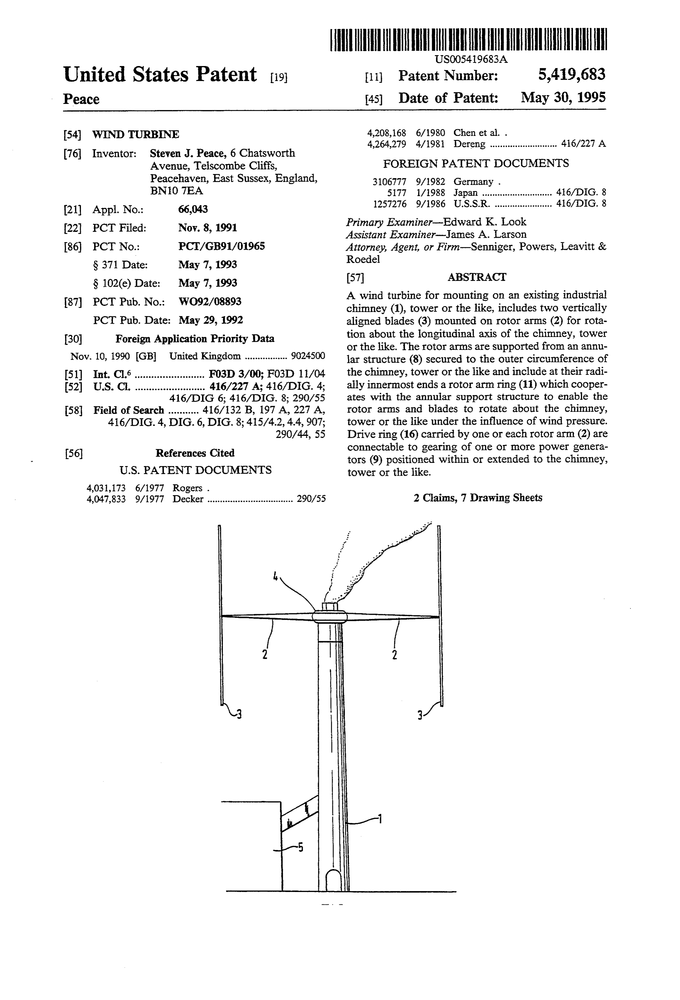
S 102(e) Date: May 7, 1993 (57) ABSTRACT 87). PCT Pub. No.: WO92/08893 A wind turbine for mounting on an existing industrial chimney (1), tower or the like, includes two vertically
PCT Pub. Date: May 29, 1992 aligned blades (3) mounted on rotor arms (2) for rota 30 Foreign Application Priority Data tion about the longitudinal axis of the chimney, tower or the like. The rotor arms are supported from an annu
Nov. 10, 1990 GB United Kingdom ................. 9024500 lar structure (8) secured to the outer circumference of 51) Int. Cl.......................... F03D 3/00; F03D 11/04 the chimney, tower or the like and include at their radi 52 U.S. C. ......................... 416/227A; 416/DIG. 4; ally innermost ends a rotor arm ring (11) which cooper 416/DIG 6; 416/DIG. 8; 290/55 ates with the annular support structure to enable the 58 Field of Search ........... 416/132 B, 197 A, 227A, rotor arms and blades to rotate about the chimney, 416/DIG.4, DIG. 6, DIG. 8; 415/4.2, 4.4,907; tower or the like under the influence of wind pressure. 290/44, 55 Drive ring (16) carried by one or each rotor arm (2) are 56 References Cited connectable to gearing of one or more power genera tors (9) positioned within or extended to the chimney,
4,047,833 9/1977 Decker .................................. 290/55 2 Claims, 7 Drawing Sheets
Page 2
Drawing sheet — no readable text.
Page 3
Drawing sheet — no readable text.
Page 4
Drawing sheet — no readable text.
Page 5
Drawing sheet — no readable text.
Page 6
Drawing sheet — no readable text.
Page 7
Drawing sheet — no readable text.
Page 8
Drawing sheet — no readable text.
Page 9
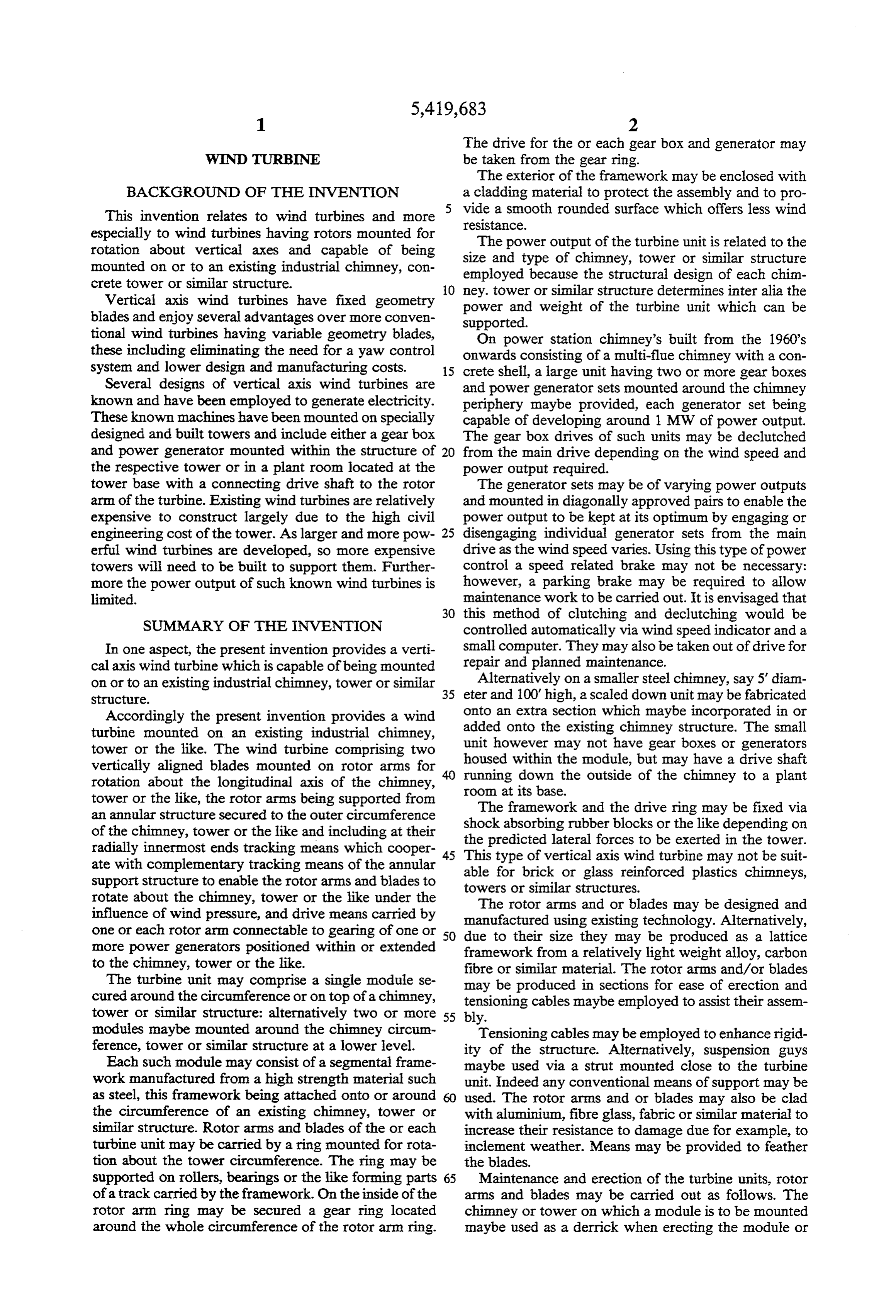
The drive for the or each gear box and generator may
WNDTURBINE be taken from the gear ring.
The exterior of the framework may be enclosed with
BACKGROUND OF THE INVENTION a cladding material to protect the assembly and to pro This invention relates to wind turbines and more vide a smooth rounded surface which offers less wind resistance.
especially to wind turbines having rotors mounted for The power output of the turbine unit is related to the rotation about vertical axes and capable of being size and type of chimney, tower or similar structure mounted on or to an existing industrial chimney, con employed because the structural design of each chim crete tower or similar structure. O ney. tower or similar structure determines inter alia the Vertical axis wind turbines have fixed geometry power and weight of the turbine unit which can be blades and enjoy several advantages over more conven supported.
tional wind turbines having variable geometry blades, On power station chimney's built from the 1960's these including eliminating the need for a yaw control onwards consisting of a multi-flue chimney with a con system and lower design and manufacturing costs. 15 crete shell, a large unit having two or more gear boxes Several designs of vertical axis wind turbines are and power generator sets mounted around the chimney known and have been employed to generate electricity. periphery maybe provided, each generator set being These known machines have been mounted on specially capable of developing around 1 MW of power output. designed and built towers and include either a gear box The gear box drives of such units may be declutched and power generator mounted within the structure of 20 from the main drive depending on the wind speed and the respective tower or in a plant room located at the power output required.
tower base with a connecting drive shaft to the rotor The generator sets may be of varying power outputs arm of the turbine. Existing wind turbines are relatively and mounted in diagonally approved pairs to enable the expensive to construct largely due to the high civil power output to be kept at its optimum by engaging or engineering cost of the tower. As larger and more pow 25 disengaging individual generator sets from the main erful wind turbines are developed, so more expensive drive as the wind speed varies. Using this type of power towers will need to be built to support them. Further control a speed related brake may not be necessary: more the power output of such known wind turbines is however, a parking brake may be required to allow limited. maintenance work to be carried out. It is envisaged that 30 this method of clutching and declutching would be
SUMMARY OF THE INVENTION controlled automatically via wind speed indicator and a In one aspect, the present invention provides a verti small computer. They may also be taken out of drive for cal axis wind turbine which is capable of being mounted repair and planned maintenance.
on or to an existing industrial chimney, tower or similar 35 Alternatively on a smaller steel chimney, say 5' diam Structure. eter and 100' high, a scaled down unit may be fabricated Accordingly the present invention provides a wind onto an extra section which maybe incorporated in or turbine mounted on an existing industrial chimney, added onto the existing chimney structure. The small tower or the like. The wind turbine comprising two unit however may not have gear boxes or generators housed within the module, but may have a drive shaft vertically aligned blades mounted on rotor arms for running down the outside of the chimney to a plant rotation about the longitudinal axis of the chimney, room at its base.
tower or the like, the rotor arms being supported from The framework and the drive ring may be fixed via an annular structure secured to the outer circumference shock absorbing rubber of the chimney, tower or the like and including at their the predicted lateral forces blocks or the like depending on radially innermost ends tracking means which cooper 45 This type of vertical axis wind to be exerted in the tower. ate with complementary tracking means of the annular able for brick or glass reinforced turbine may not be suit support structure to enable the rotor arms and blades to towers or similar structures. plastics chimneys, rotate about the chimney, tower or the like under the The rotor arms and or blades may be designed and influence of wind pressure, and drive means carried by manufactured using existing technology. Alternatively, one or each rotor arm connectable to gearing of one or 50 due to their size they may be produced as a lattice more power generators positioned within or extended framework from a relatively light weight alloy, carbon to the chimney, tower or the like. fibre or similar material. The rotor arms and/or blades The turbine unit may comprise a single module se may be produced in sections for ease of erection and cured around the circumference or on top of a chimney, tensioning cables maybe employed to assist their assem tower or similar structure: alternatively two or more 55 bly.
modules maybe mounted around the chimney circum Tensioning cables may be employed to enhance rigid ference, tower or similar structure at a lower level. ity of the structure. Alternatively, suspension guys Each such module may consist of a segmental frame maybe used via a strut mounted close to the turbine work manufactured from a high strength material such unit. Indeed any conventional means of support may be as steel, this framework being attached onto or around used. The rotor arms and or blades may also be clad the circumference of an existing chimney, tower or with aluminium, fibreglass, fabric or similar material to similar structure. Rotor arms and blades of the or each increase their resistance to damage due for example, to turbine unit may be carried by a ring mounted for rota inclement weather. Means may be provided to feather tion about the tower circumference. The ring may be the blades.
supported on rollers, bearings or the like forming parts 65 Maintenance and erection of the turbine units, rotor of a track carried by the framework. On the inside of the arms and blades may be carried out as follows. The rotor arm ring may be secured a gear ring located chimney or tower on which a module is to be mounted around the whole circumference of the rotor arm ring. maybe used as a derrick when erecting the module or
Page 10
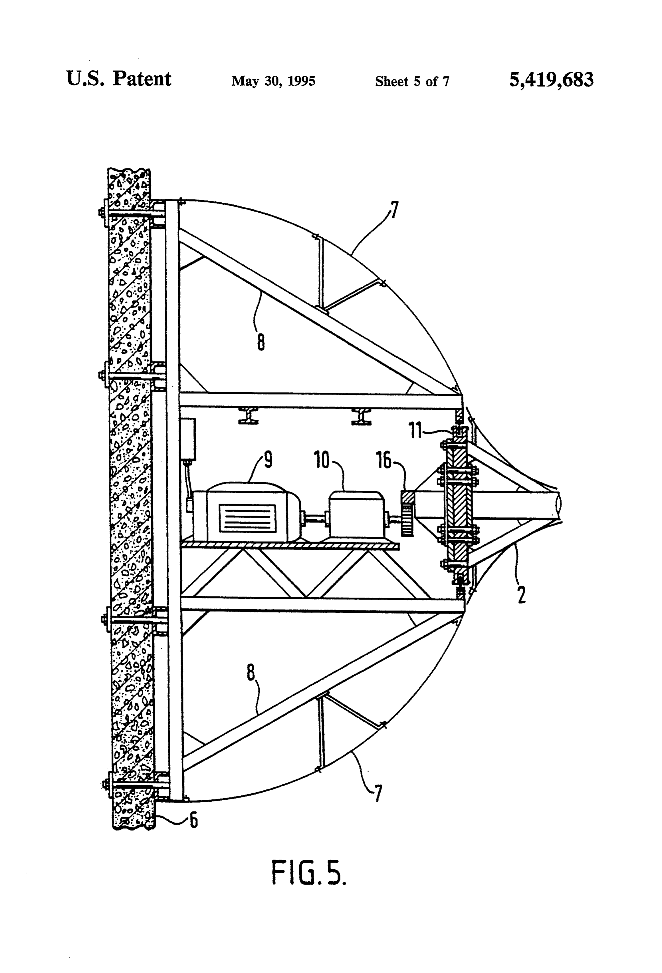
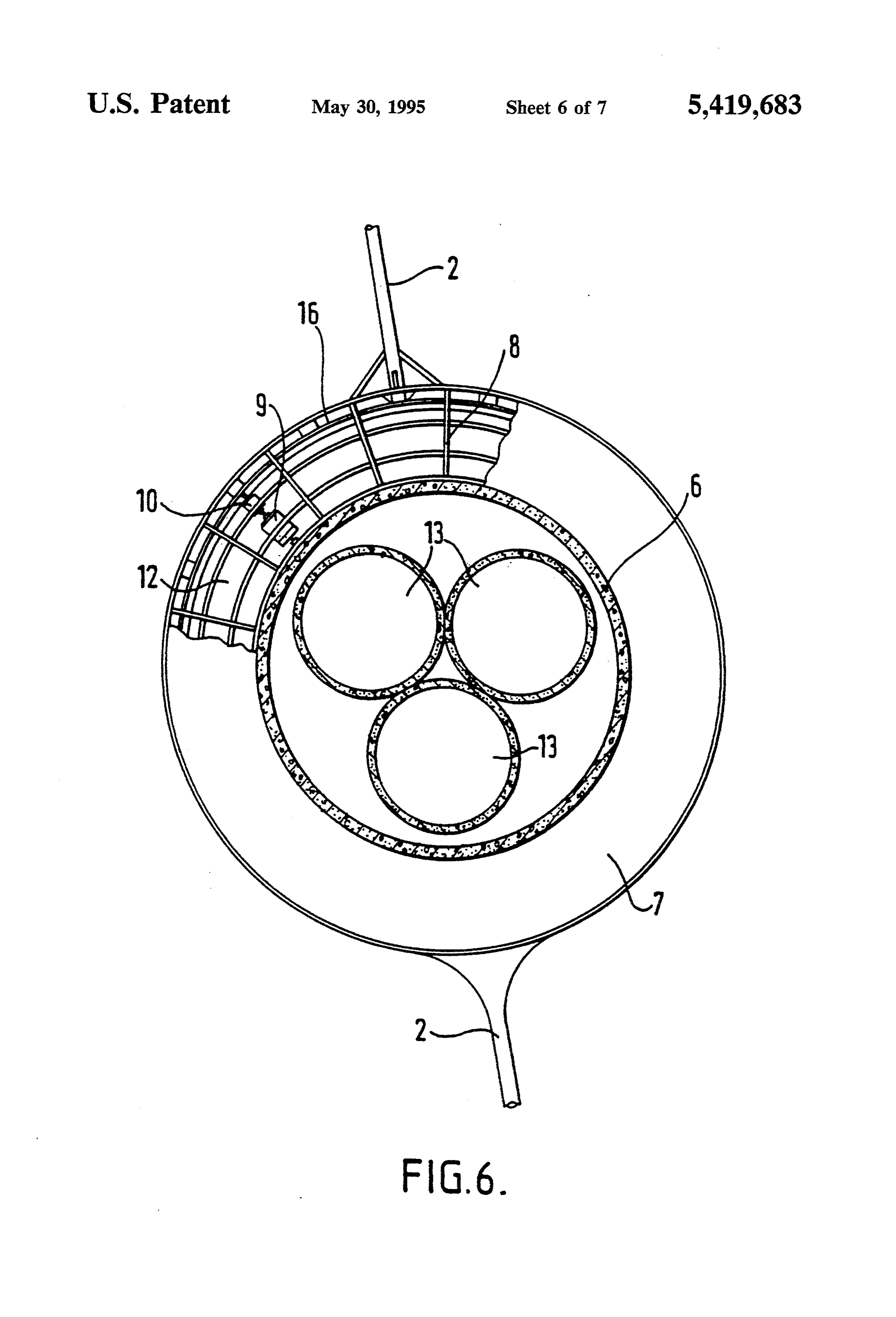
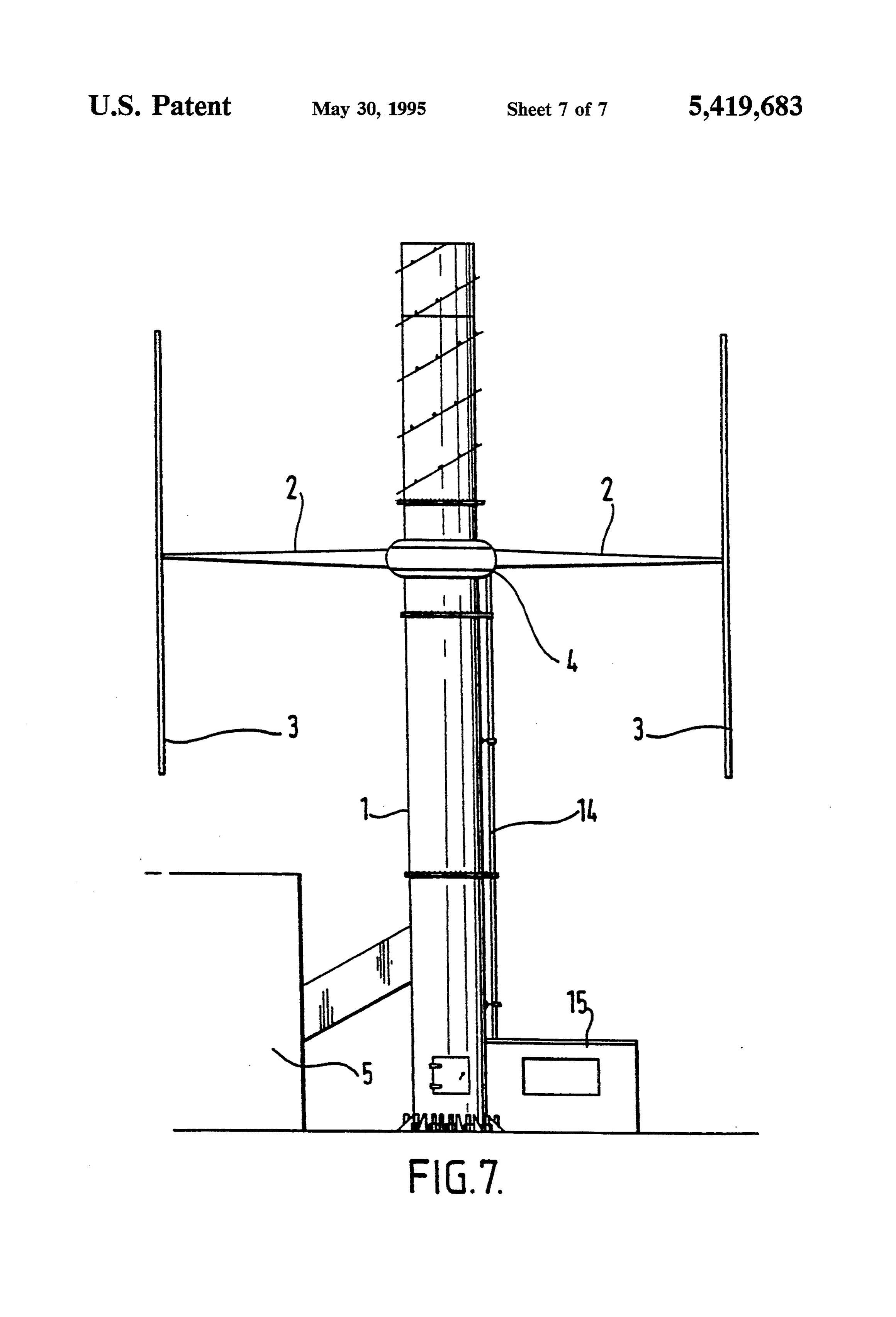
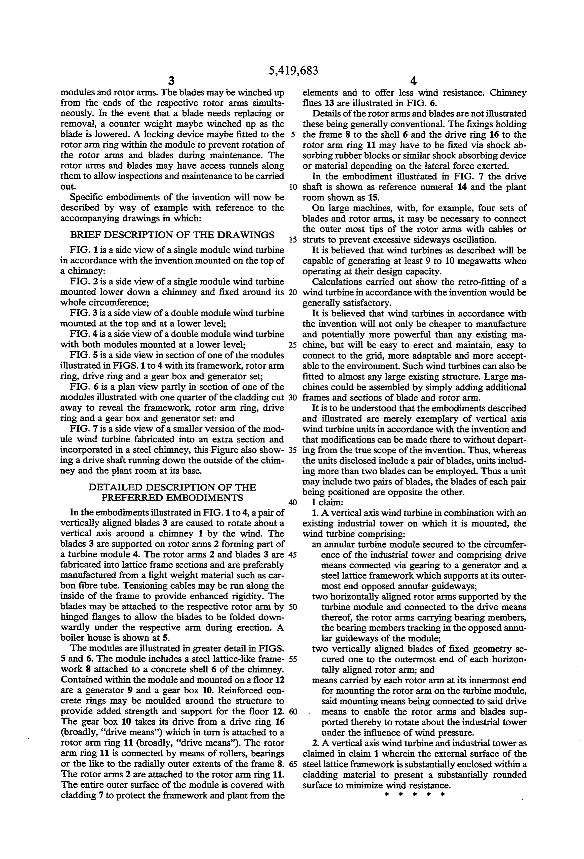
modules and rotor arms. The blades may be winched up elements and to offer less wind resistance. Chimney from the ends of the respective rotor arms simulta flues 13 are illustrated in FIG. 6. neously. In the event that a blade needs replacing or Details of the rotor arms and blades are not illustrated removal, a counter weight maybe winched up as the these being generally conventional. The fixings holding blade is lowered. A locking device maybe fitted to the 5 the frame 8 to the shell 6 and the drive ring 16 to the rotor arm ring within the module to prevent rotation of rotor arm ring 11 may have to be fixed via shock ab the rotor arms and blades during maintenance. The sorbing rubber blocks or similar shock absorbing device rotor arms and blades may have access tunnels along or material depending on the lateral force exerted. them to allow inspections and maintenance to be carried In the embodiment illustrated in FIG. 7 the drive Out. O shaft is shown as reference numeral 14 and the plant Specific embodiments of the invention will now be room shown as 15.
described by way of example with reference to the On large machines, with, for example, four sets of accompanying drawings in which: blades and rotor arms, it may be necessary to connect BRIEF DESCRIPTION OF THE DRAWINGS the outer most tips of the rotor arms with cables or 5 struts to prevent excessive sideways oscillation.
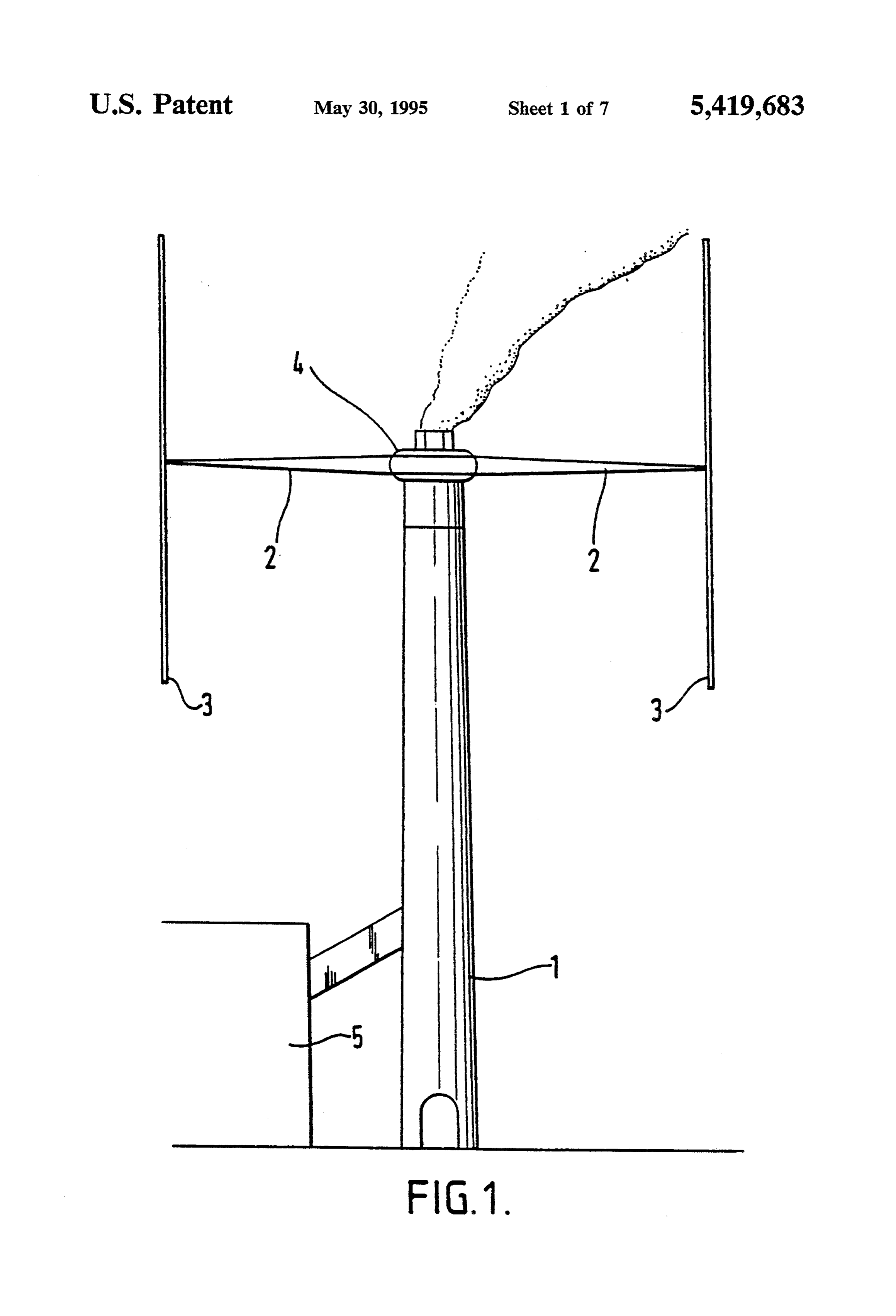
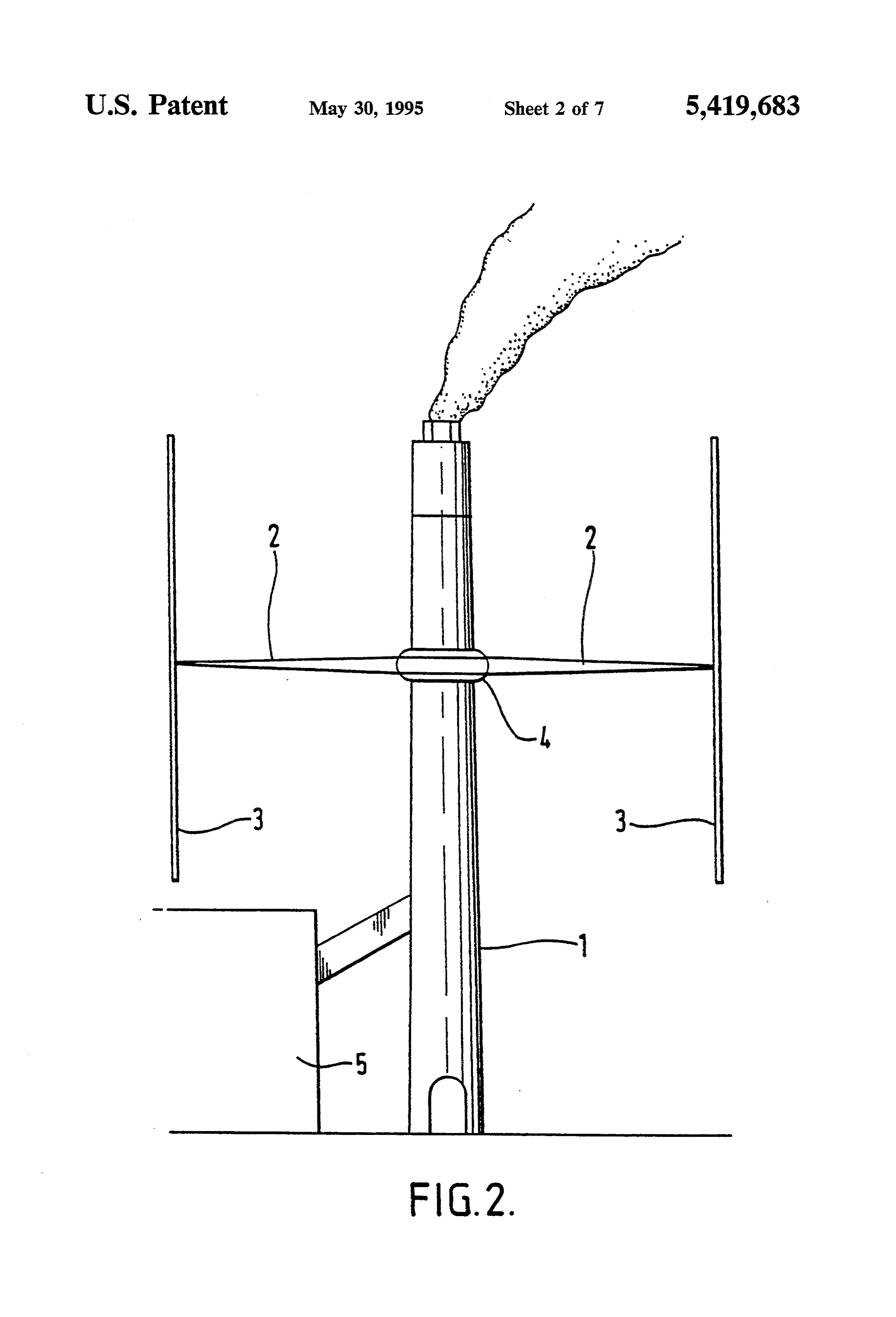
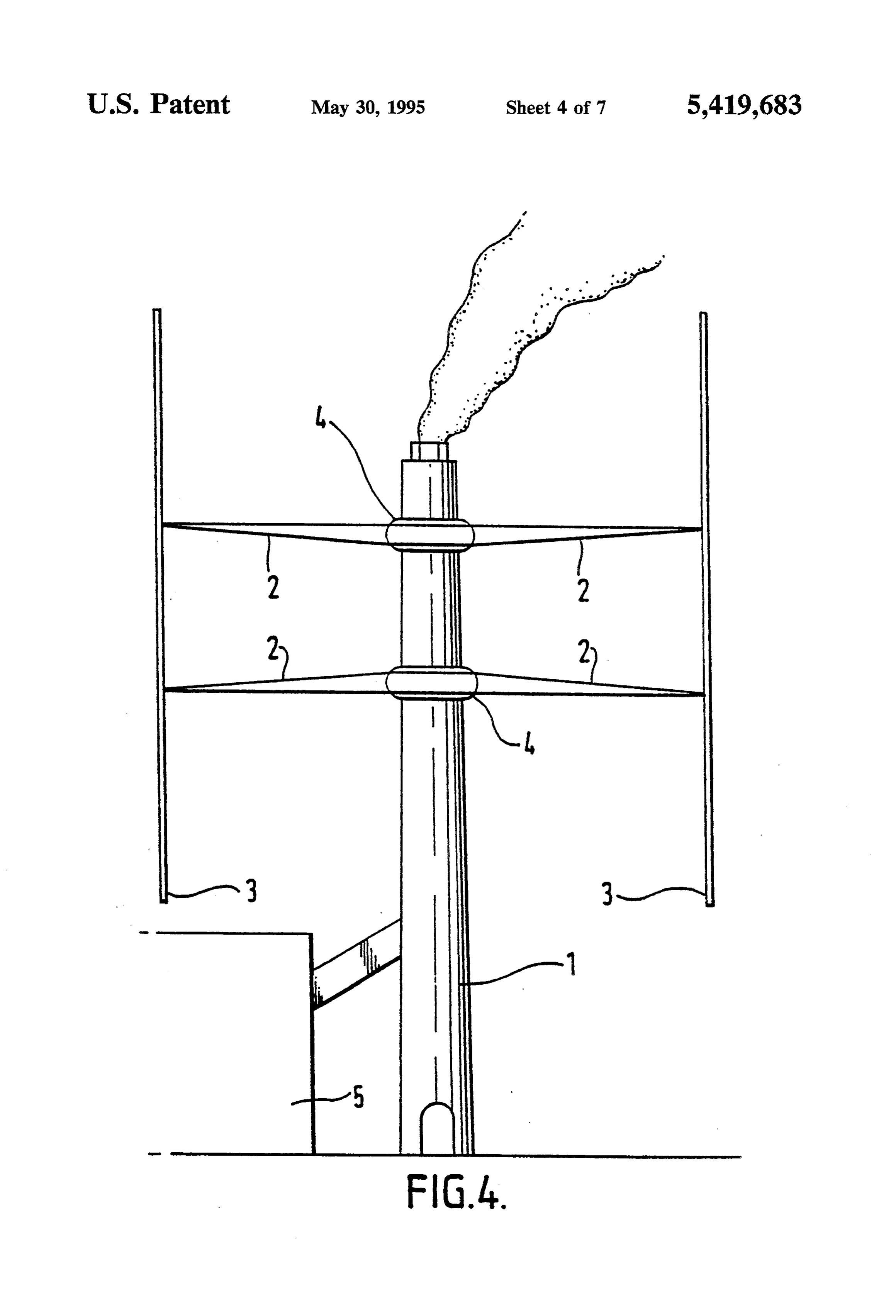
FIG. 1 is a side view of a single module wind turbine It is believed that wind turbines as described will be in accordance with the invention mounted on the top of capable of generating at least 9 to 10 megawatts when a chimney: operating at their design capacity. FIG. 2 is a side view of a single module wind turbine Calculations carried out show the retro-fitting of a mounted lower down a chimney and fixed around its 20 wind turbine in accordance with the invention would be whole circumference; generally satisfactory.
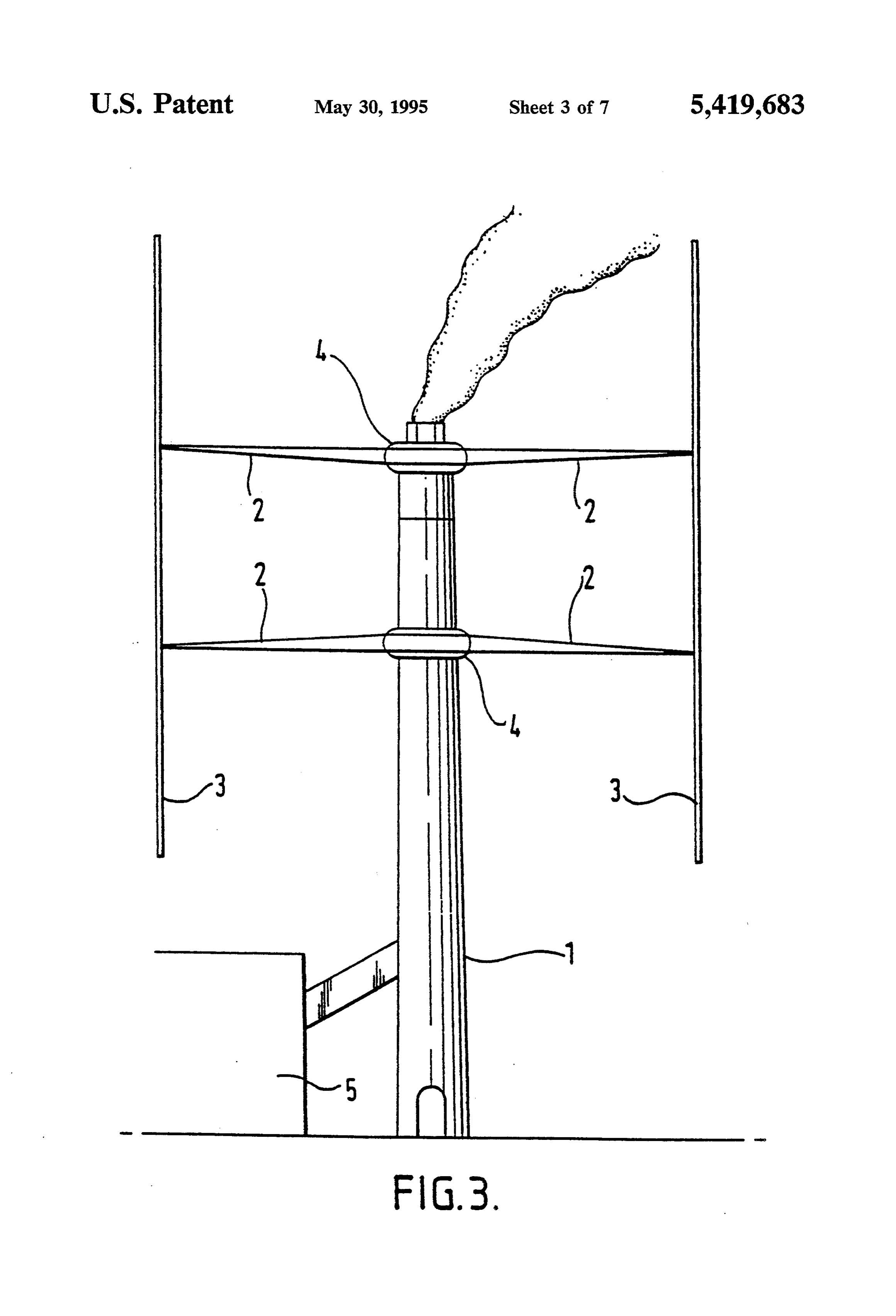
FIG. 3 is a side view of a double module wind turbine It is believed that wind turbines in accordance with mounted at the top and at a lower level; the invention will not only be cheaper to manufacture FIG. 4 is a side view of a double module wind turbine and potentially more powerful than any existing ma with both modules mounted at a lower level; 25 chine, but will be easy to erect and maintain, easy to FIG. 5 is a side view in section of one of the modules connect to the grid, more adaptable and more accept illustrated in FIGS. 1 to 4 with its framework, rotor arm able to the environment. Such wind turbines can also be ring, drive ring and a gear box and generator set; fitted to almost any large existing structure. Large ma FIG. 6 is a plan view partly in section of one of the chines could be assembled by simply adding additional modules illustrated with one quarter of the cladding cut frames and sections of blade and rotor arm. away to reveal the framework, rotor arm ring, drive It is to be understood that the embodiments described ring and a gear box and generator set: and and illustrated are merely exemplary of vertical axis FIG. 7 is a side view of a smaller version of the mod wind turbine units in accordance with the invention and ule wind turbine fabricated into an extra section and that modifications can be made there to without depart incorporated in a steel chimney, this Figure also show 35 ing from the true scope of the invention. Thus, whereas ing a drive shaft running down the outside of the chim the units disclosed include a pair of blades, units includ ney and the plant room at its base. ing more than two blades can be employed. Thus a unit DETAILED DESCRIPTION OF THE may include two pairs of blades, the blades of each pair PREFERRED EMBOOMENTS being positioned are opposite the other.
In the embodiments illustrated in FIG. 1 to 4, a pair of 1. A vertical axis wind turbine in combination with an vertically aligned blades 3 are caused to rotate about a existing industrial tower on which it is mounted, the vertical axis around a chimney 1 by the wind. The wind turbine comprising:
blades 3 are supported on rotor arms 2 forming part of an annular turbine module secured to the circumfer a turbine module 4. The rotor arms 2 and blades 3 are 45 ence of the industrial tower and comprising drive fabricated into lattice frame sections and are preferably means connected via gearing to a generator and a manufactured from a light weight material such as car steel lattice framework which supports at its outer bon fibre tube. Tensioning cables may be run along the most end opposed annular guideways; inside of the frame to provide enhanced rigidity. The two horizontally aligned rotor arms supported by the blades may be attached to the respective rotor arm by SO turbine module and connected to the drive means hinged flanges to allow the blades to be folded down thereof, the rotor arms carrying bearing members, wardly under the respective arm during erection. A the bearing members tracking in the opposed annu boiler house is shown at 5. lar guideways of the module; The modules are illustrated in greater detail in FIGS. two vertically aligned blades of fixed geometry se 5 and 6. The module includes a steel lattice-like frame 55 cured one to the outermost end of each horizon work 8 attached to a concrete shell 6 of the chimney. tally aligned rotor arm; and Contained within the module and mounted on a floor 12 means carried by each rotor arm at its innermost end are a generator 9 and a gear box 10. Reinforced con for mounting the rotor arm on the turbine module, Crete rings may be moulded around the structure to said mounting means being connected to said drive provide added strength and support for the floor 12. means to enable the rotor arms and blades sup The gear box. 10 takes its drive from a drive ring 16 ported thereby to rotate about the industrial tower (broadly, "drive means’) which in turn is attached to a under the influence of wind pressure. rotor arm ring 11 (broadly, “drive means'). The rotor 2. A vertical axis wind turbine and industrial tower as arm ring 11 is connected by means of rollers, bearings claimed in claim 1 wherein the external surface of the or the like to the radially outer extents of the frame 8. 65 steel lattice framework is substantially enclosed within a The rotor arms 2 are attached to the rotor arm ring 11. cladding material to present a substantially rounded The entire outer surface of the module is covered with surface to minimize wind resistance. cladding 7 to protect the framework and plant from the s al :
Provenance
- Collection
- Cited prior art
- Original PDF
- patentimages.storage.googleapis.com →
- Filed
- 1991-11-08
- Pages
- 10
- Method
- pdftotext (the PDF's own text layer) + pdftoppm 300dpi page scans
- Source
- Google Patents bibliographic record
- Granted
- 1995-05-30
- Inventors
- Steven J. Peace
- Transcribed from
- patentimages.storage.googleapis.com →