patent · US5986374
Vehicle mounted motor with rotor having ferrite magnet section with embedded permanent magnet pieces therein
16 November 1999
Page 1 — bibliographic record
United States Patent (19) 11 Patent Number: 5,986,374 Kawakami (45) Date of Patent: Nov. 16, 1999 54) VEHICLE MOUNTED MOTOR WITH 3,979,822 9/1976 Halm ......................................... 29/596 ROTOR HAVING FERRITE MAGNET 4,127,786 11/1978 Volkrodt. ... 310/156 SECTION WITH EMBEDDED PERMANENT 4,131,988 1/1979 Finegold . ... 29/596 MAGNET PIECES THEREN 4,625,135 11/1986 Kasabian. ... 310/156 5,066,880 11/1991 Banon ..................................... 310/156 75 Inventor: Tsukasa Kawakami, Obama, Japan 5,397.951 3/1995 Uchida et al.. 5,563,463 10/1996 Stark ....................................... 310/156 73 Assignee: Shibaura Engineering Works Co., 5,684.352 11/1997 Mita et al. .............................. 310/156 Ltd., Tokyo, Japan 5,811,904 9/1998 Tajima et al. ........................... 310/156 21 Appl. No.: 09/289,687 FOREIGN PATENT DOCUMENTS
Related U.S. Application Data 62 Division of application No. 09/091,941, filed as application Primary Examiner Thomas M. Dougherty No. PCT/JP96/02929, Oct. 9, 1996. Assistant Examiner Tran N Nguyen 30 Foreign Application Priority Data Attorney, Agent, or Firm-Christensen O'Connor Johnson Jan. 18, 1996 JP Japan .................................... s & Kindness PLLC
Jan. 25, 1996 JP Japan .... 8-010865 57 ABSTRACT
Jan. 25, 1996 JP Japan .... A motor mounted in a vehicle having ferrite magnet Section Jan. 25, 1996 JP Japan .... -- --- - 8-010868
formed as a rotor core. The ferrite magnet Section has a (51) Int. Cl. ............................................... HO2K 21/12 plurality of recesses, or through holes, circumferentially 52 U.S. Cl. .................. 310/156; 310/216; 310/261 provided along an axial direction in a Space-apart relation. A 58 Field of Search ..................................... 310/156, 152, plurality of permanent magnet pieces are respectively fitted 310/261, 157, 262, 216, 218; 360/99.08, in the corresponding receSS of the ferrite magnet Section. 98.07, 99.04, 97.02,596,598 The permanent magnet pieces are made of a permanent 56) References Cited magnetic material which has greater ferromagnetic property than that of the ferrite magnet Section.
2.961,555 11/1960 Towne ..................................... 310/156 6 Claims, 11 Drawing Sheets
va INSERT
Page 2
Drawing sheet — no readable text.
Page 3
Drawing sheet — no readable text.
Page 4
Drawing sheet — no readable text.
Page 5
Drawing sheet — no readable text.

Page 6
Drawing sheet — no readable text.
Page 7
Drawing sheet — no readable text.
Page 8
Drawing sheet — no readable text.
Page 9
Drawing sheet — no readable text.
Page 10
Drawing sheet — no readable text.
Page 11
Drawing sheet — no readable text.
Page 12
Drawing sheet — no readable text.
Page 13
VEHICLE MOUNTED MOTOR WITH wire portions and this presents the problem of the winding ROTOR HAVING FERRITE MAGNET 104 being reduced in its Space occupation percentage. For SECTION WITH EMBEDDED PERMANENT the winding 105 comprised of the flat band-like copper wire MAGNET PIECES THEREN as shown in FIG. 2, there is leSS space between the adjacent band-like portions. For a winding 105 with one terminal end
This application is a divisional of U.S. patent application portion 105a of its turned section exposed to an outside as Ser. No. 09/091,941, filed Oct. 9, 1996, which is a U.S. shown in FIG. 3, an initial end portion 105b is hidden at the national application corresponding to copending interna inside of the turned Section around a projection 102 and it is tional application PCT/JP96/02929, filed Jun. 25, 1998, difficult to achieve the soldering of a lead wire's end portion which designates the United States, the benefit of the filing externally.
dates of which is hereby claimed under 35 U.S.C. S 120, the The rotor, on the other hand, comprises a cylindrical international application in turn claiming the benefit of Section having a plurality of Sector-like permanent magnet Japanese applications No. 8-006,416, filed Jan. 18, 1996; pieces formed of ferrite magnets and combined into a No. 8-010,865, filed Jan. 25, 1996; No. 8-010,866, filed Jan. cylindrical unit and a rotation Shaft fixed at the center of the 25, 1996; No. 8-010,867, filed Jan. 25, 1996; and No. 15 cylindrical Section.
8-010,868, filed Jan. 25, 1996, the benefit of the filing dates Even if the motor in the vehicle is to be so made as to have of which is hereby claimed under 35 U.S.C. S 119. high efficiency and high output level, the rotor using the TECHNICAL FIELD ferrite magnet is limited in terms of the magnetic Strength of the ferrite magnet. It may be possible to improve the
The present invention relates to an electric motor mounted magnetic Strength using, for example, the rare earth magnet in a vehicle, Such as a passenger car and truck. in place of the ferrite magnet. The rare earth magnet is PRIOR ART higher in cost than the ferrite magnet and, if the rare earth magnet is used for the rotor of the motor in the vehicle, then
In a vehicle Such as a passenger car and truck, various the manufacturing cost becomes expensive.
motors are mounted Such as a motor mounted on an engine 25 and a motor for driving a wiper. DISCLOSURE OF THE INVENTION The motor mounted in the vehicle has a cylindrical stator An object of the present invention is to provide a motor and a rotor rotatably mounted at the central area of the Stator mounted in a vehicle, which is excellent in its vibration in which the rotor is equipped with a permanent magnet and resistance and in its impact resistance. produces a rotational force under a magnetic field created by the Stator. Another object of the present invention is to provide a In the stator of the motor mounted in the vehicle, use is motor mounted in a vehicle, which can improve a Space made, as a structure for forming coils for creating magnetic end portionspercentage occupation and ensure ready connection of the of a winding to external lead wires.
fields, of cylindrical ring Sections arranged coaxial with a 35 rotor and a plurality of projections equidistantly mounted Another object of the present invention is to provide a on, and along a circumferential direction of, the cylindrical motor mounted in a vehicle, which can ensure high effi ring unit and directed at their forward ends toward the rotor ciency and high output power through the effective use of a Side with each projection wound with a winding Such as a relatively hard-to-get magnet material.
copper wire. A magnetic field is created by carrying electric 40 The vehicle motor as set out in claim 1 of the present current in the windings of these coils through lead wires invention is comprised of a one-piece unit molded with a from an external Source. molding resin and having a Stator, lead wires of coils in the In this case, the end of the winding constituting the coil Stator and interconnect members connecting the lead wires is connected to the end of the lead wire in the following way. to an outside of the vehicle motor. That is, the end of the winding is soldered to the end of the 45 The vehicle motor of claim 2 is of such a type that, in the lead wire and the ends of the winding and lead wire are tied arrangement of claim 1, the interconnect members comprise together by a band, etc., along the Stator and fixed together an electro-conductive layer Section having a coil connection and then bonded with a varnish, etc. They may also be Section and external terminal Section and an insulating layer connected and fixed through a PC board, etc. Section Stacked on the electro-conductive layer Section and If, as Set out above, the end portions of the copper wire 50 the lead wires of the coils are connected to the coil connec and lead wire are tied together and fixed or they are fixed tion Section and the lead wires are connected to the external together through the PC plate, there is Sometimes a chance terminal Section.
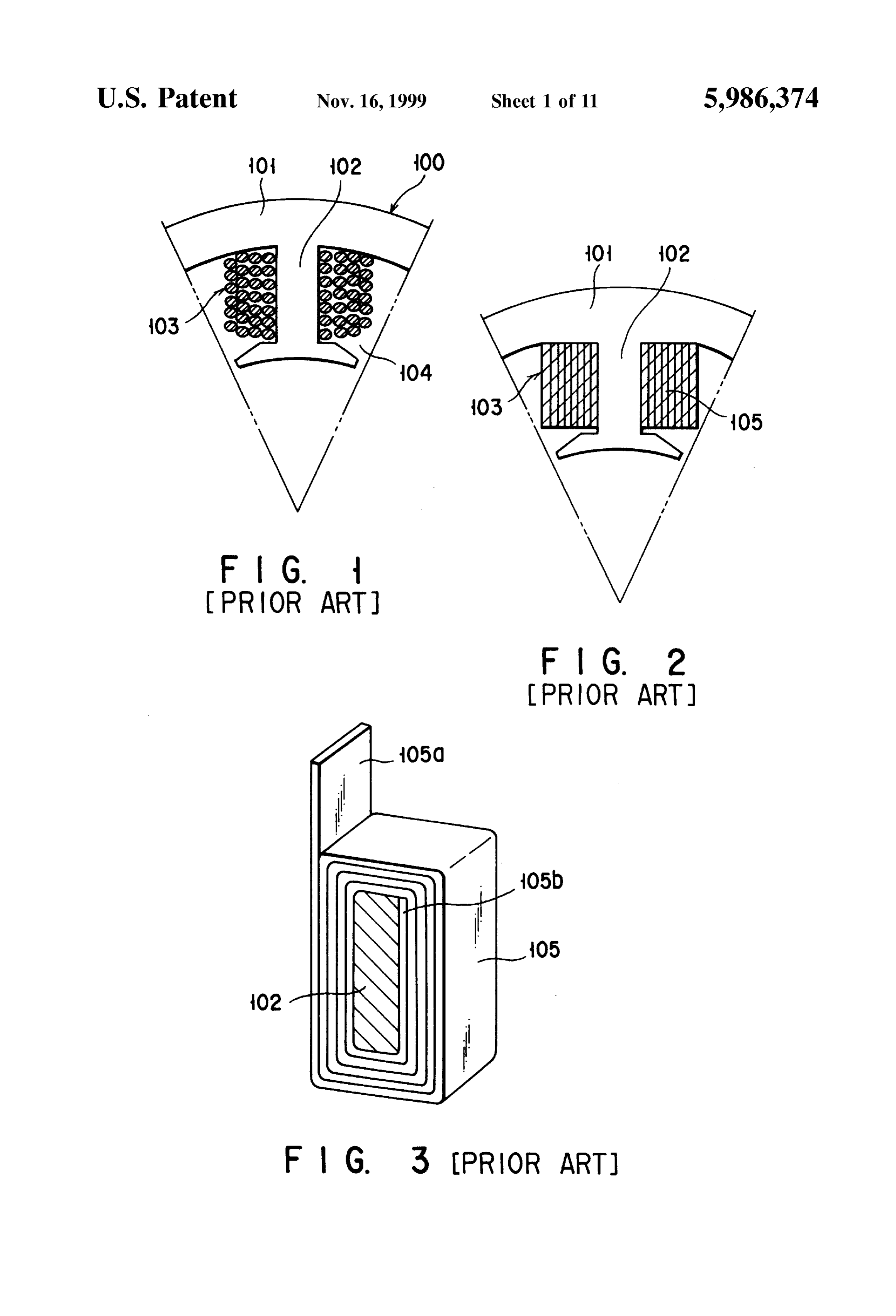
that their fixed areas are disconnected due to a vibration The vehicle motor of claim 3 is of such a type that, in the resulting from the running of the vehicle. As a result, the arrangement shown in FIG. 2, the interconnect members are problem arises because of lowered vibration resistance and 55 Substantially ring-like in configuration, the coil connection impact resistance in the vehicle. Further, for the former Section and external terminal Section are projected from the method it is necessary to tie together the end portions of the outer periphery of the electro-conductive layer Section, winding and lead wire during a manufacturing of the vehicle tape-like coils are wound on the Stator and the lead wire of motor. This operation is time-consuming and tedious. the tape-like coil is electrically connected to the coil con As shown in FIG. 1, on the other hand, a winding 104 is 60 nection Section.
formed with a coil 103 provided around a projection 102 of The vehicle motor is one piece molded with the molding a ring section 101 of a stator 100 and it may also constitute resin and has a Stator, coils and interconnect members and a winding 105 having a copper wire circular in cross-section possesses excellent vibration resistance and impact resis or a length of a flat band-like copper wire as shown in FIG. tance. Therefore, there is no chance of disconnection at an 2. 65 areas between the lead wires of the coils and the interconnect For the winding 104 comprised of a copper wire as shown members. Thus, added reliability can be obtained on the in FIG. 1, interstices are created among the adjacent copper motor mounted in the vehicle.
Page 14
The vehicle motor according to claim 4 of the present circumferential direction and a receSS is provided at a middle invention is of Such a type that the winding on the Stator is of each magnetic pole. It is, therefore, possible to increase, comprised of a flat band-like copper wire and comprises a in a proper timing, the density of a magnetic flux generated first band-like wire wound on the stator in a radially inward from the permanent magnet Section. direction of the Stator, a connection Section continuous with The vehicle motor as claimed in claim 9 includes a rotor one longitudinal end of the first band-like Section and comprising a permanent magnet Section formed as a cylin extending in a radially outward direction, and a Second drical Section from a ferrite magnet material and having a band-like Section continuous with a radially outward end of plurality of through holes circumferentially provided in its the connection Section, extending in a direction opposite to inner Surface in a Spaced-apart relation along an axial that of the first band-like Section, and wound on the Stator. direction and magnet pieces greater in ferromagnetic prop By doing So, the first and Second band-like Sections are erty than the ferrets magnet material and each fitted in the wound at radially different areas on the stator with the corresponding through hole in the permanent magnet Sec connection Section as a reference position. Their free end tion.
portions are each exposed to an outside, thus making it In consequence, the magnetic flux generated from the easier to make connection to the outside conductors. Since 15 permanent magnet Section has its density increased and it is a flat band-like copper wire is used as the winding, there is possible to achieve the vehicle motor of high efficiency and no clearance between the adjacent turned portions of the coil high output power. Even in the situation where the magnet and it is possible to improve a Space occupation percentage material greater in ferromagnetic property than the ferrite of the winding. magnet material is expensive and not readily available, Such In the invention as claimed in claim 5, the first and Second a ferromagnetic material is partly used in an effective way, band-like Sections are wound on the Stator in mutually So that the resultant motor involves no greater additional opposite directions with a midpoint of the connection Sec cost. It is, therefore, possible to obtain an otherwise rela tion as a reference position and, even in this case, it is tively hard-to get magnet material readily. possible to realize the above-mentioned advantage. Further, in the invention claimed in claim 10, the perma In the invention as claimed in claim 6, the Second band 25 nent magnet Section has a plurality of magnetic poles along like section extends farther in length than the first band-like its periphery and the through holes are provided at the Section. middle of the respective magnet and the magnetic flux By doing So, the first and Second band-like Sections are created from the permanent magnetic Section can have its wound on the radially different areas of the stator with the density increased in a proper timing. connection Section as a reference position. In the Sector area Further, in the invention as claimed in claim 11, the of a unit angle from the center of the motor, the length of the through hole is provided at a plurality of places along the circumferential area is greater toward the radially outward axial direction of the permanent magnet Section in a Spaced direction and the Space size is increased. According to the apart relation. In this case, less amount of magnetic piece winding of the present invention, the Second band-like 35 can be used without incurring any large additional cost and Section situated toward the radially outward direction is it is possible to readily utilize the relatively hard-to-get made longer than the first band-like Section Situated toward magnet material effectively So that added advantage can be the radially inward direction and the coil, thus provided, obtained.
becomes thicker, in its turned portion, toward the radially In the invention as claimed in claim 12, the magnetic outward direction. This provides a greater Space occupation 40 piece is made thinner than the permanent magnet Section and percentage to the winding. Further, the flat band-like copper a yoke made of a magnetic material is arranged in the wire is used as the winding and no clearance is produced at radially inward direction of the magnetic piece. In this case, those areas between the turned portions of the coil and hence the amount of Such magnetic piece can be reduced Still the winding provides an improved space occupation per further without incurring any greater additional cost and it is centage. Further, both the free end portions of the winding 45 possible to readily and effectively use an otherwise rela are exposed to the outside, thus ensuring the easineSS with tively hard-to-get magnet material and to obtain added which they are connected to external conductors. advantage.
The vehicle motor as claimed in claim 7 includes a rotor comprising a permanent magnet Section formed as a cylin BRIEF DESCRIPTION OF THE DRAWINGS drical Section, made of a ferrite magnet material and having 50 FIG. 1 is a croSS-Sectional view showing one example of a plurality of recesses circumferentially provided in a the coil of a Stator incorporated in a conventional vehicle Spaced-apart relation in an inner wall Surface of the cylin motor, drical Section and magnet pieces greater in ferromagnetic FIG. 2 is a cross-sectional view showing another example property than a ferrite magnet material and each fitted in the of the coil of a Stator incorporated in a conventional vehicle corresponding receSS in the permanent magnet. 55 motor,
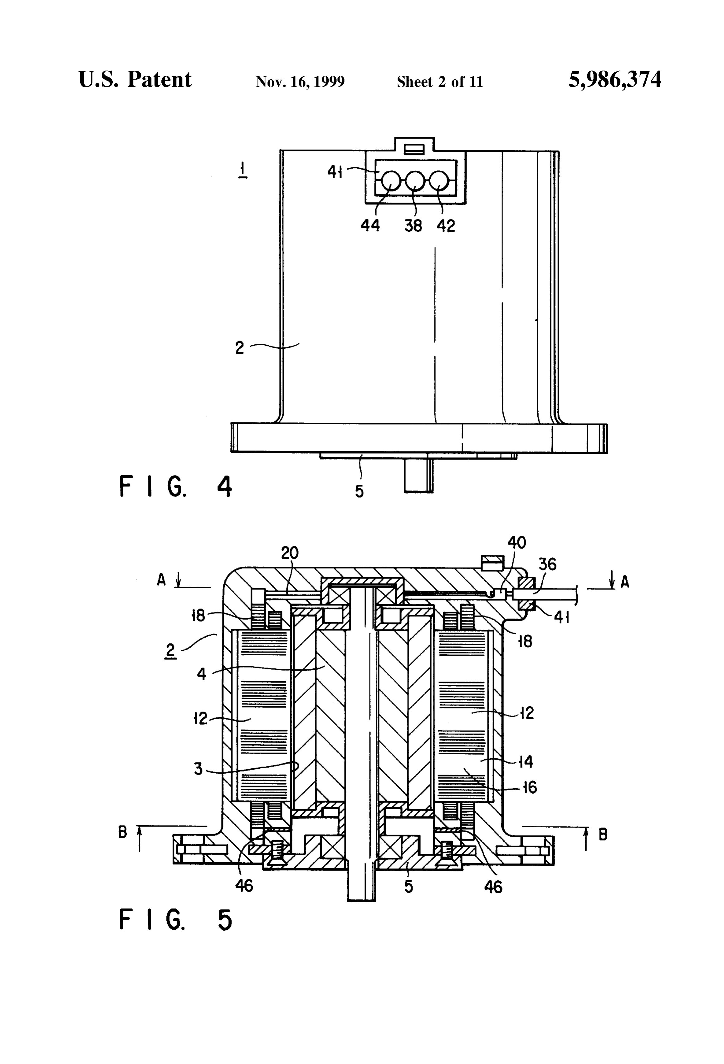
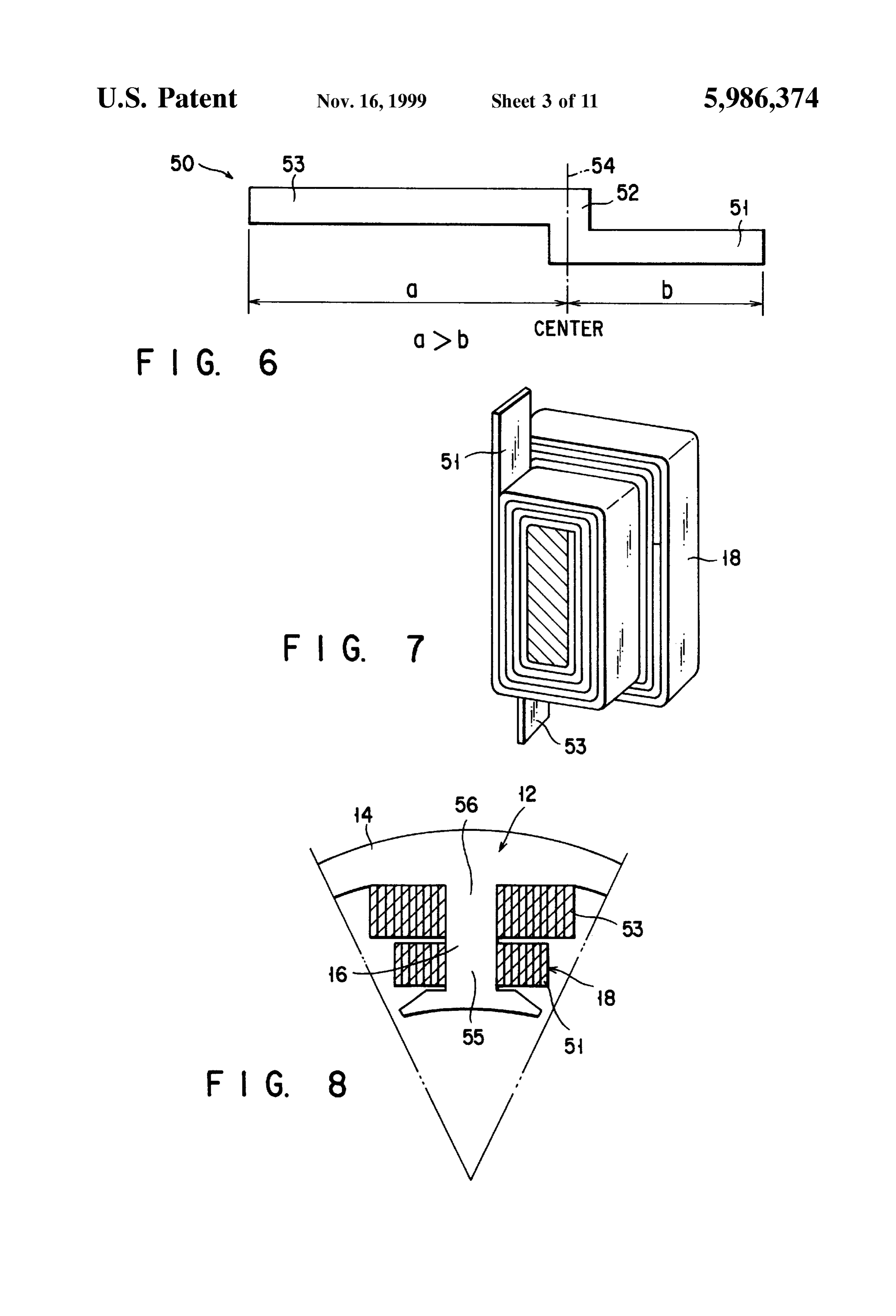
AS a result, the magnetic flux resulting from the perma FIG. 3 is a perspective view showing the same type of nent magnet has its density increased and it is possible to conventional coil as Set out above;
provide high efficiency and high output power to the motor. FIG. 4 is a front view showing a vehicle motor showing In view of the fact that a magnet material greater in ferromagnetic property than the ferrite magnet material is 60 one embodiment of the present invention; expensive and hard to get, the ferromagnetic material is FIG. 5 is a vertical cross-section of the vehicle motor; partly used relative to the permanent magnet So that no FIG. 6 is an expanded view of a winding; greater extra cost is incurred in the manufacture of the FIG. 7 is a perspective view of a coil; vehicle motor and Such a hard-to-get magnet material can be FIG. 8 is a croSS-Sectional view showing a major Section effectively used. 65 of a Stator having a winding,
In the invention as claimed in claim 8, the permanent FIG. 9 is a cross-sectional view as taken along line A-A magnet Section has a plurality of magnetic poles along its in FIG. 5;
Page 15
S 6
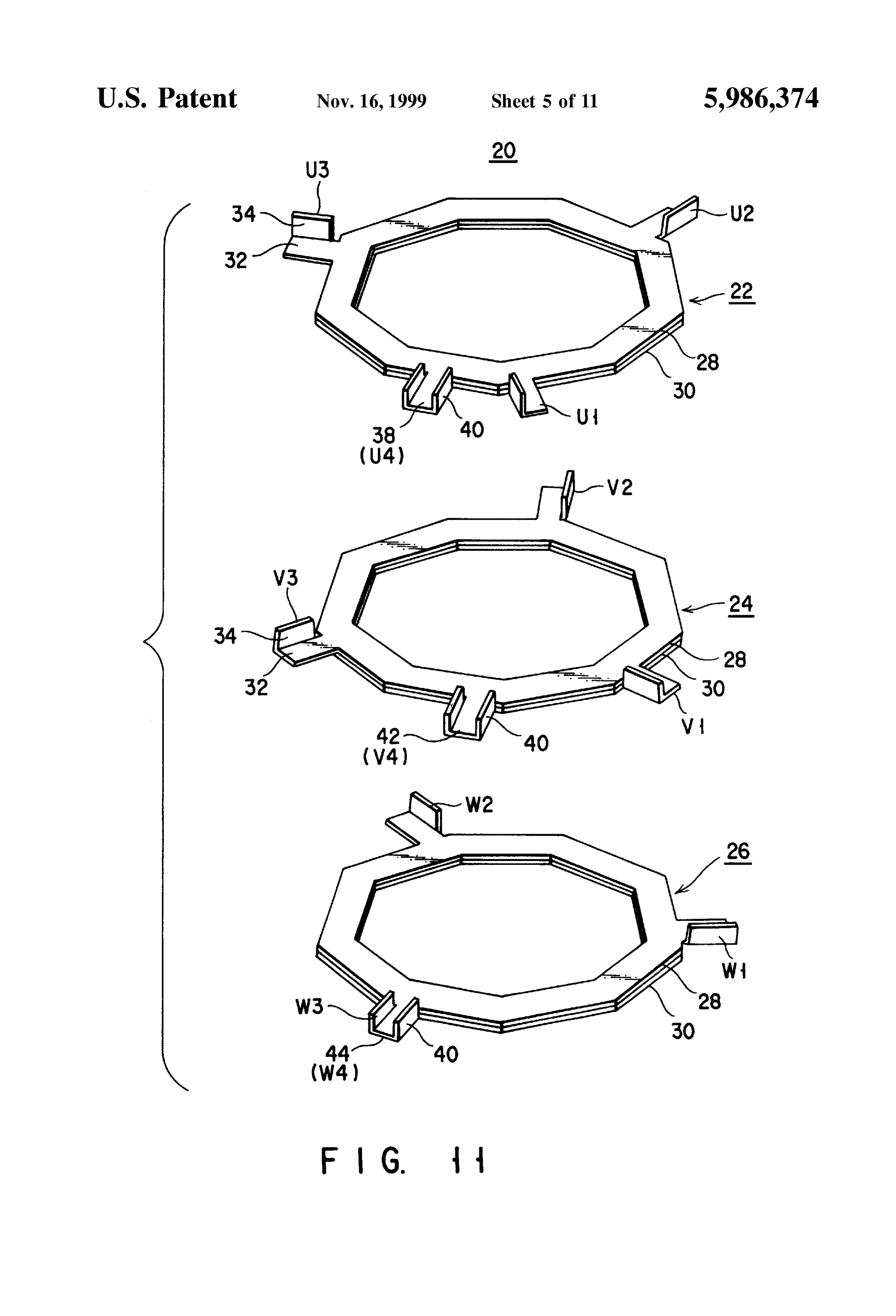
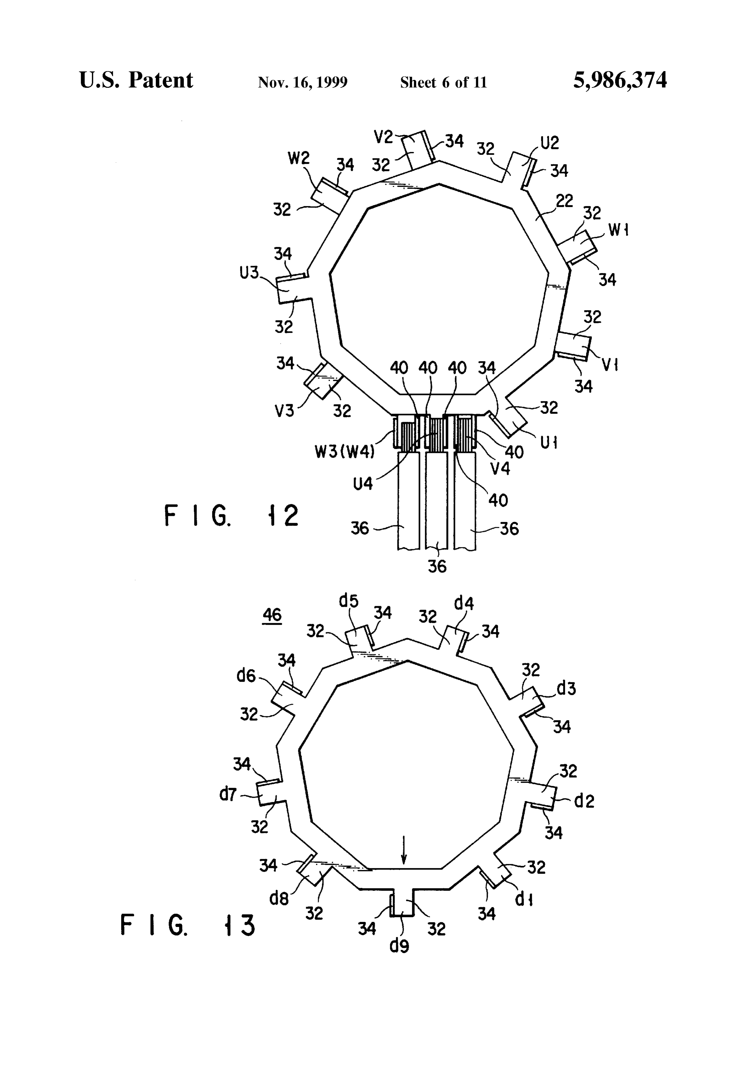
FIG. 10 is a cross-sectional view as taken along line B-B The Stator 12 has a ring Section 14 and nine projections 16 in FIG. 5; inwardly extending from the ring Section 14. The projection FIG. 11 is an exploded, perspective view showing an 16 provides a T-shape configuration in plan View. interconnect member; The upper end portion of the coil 18 (lead wire of the coil FIG. 12 is a plan View showing another interconnect 18) comprised of a winding of a flat tape-like copper wire 18 member; and wrapped around each projection 16 of the Stator 12 is FIG. 13 is a plan view showing another interconnect brought out above the stator 12 and the lower end portion of member; the coil 18 (lead wire of the coil 18) is brought out below the stator 12.
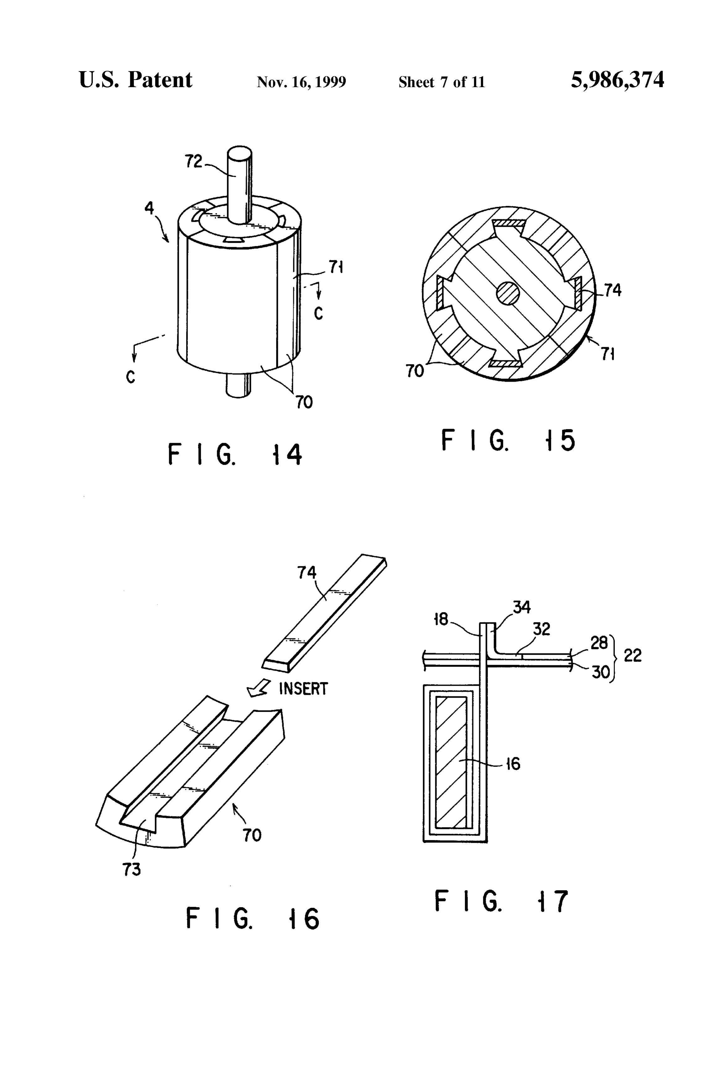
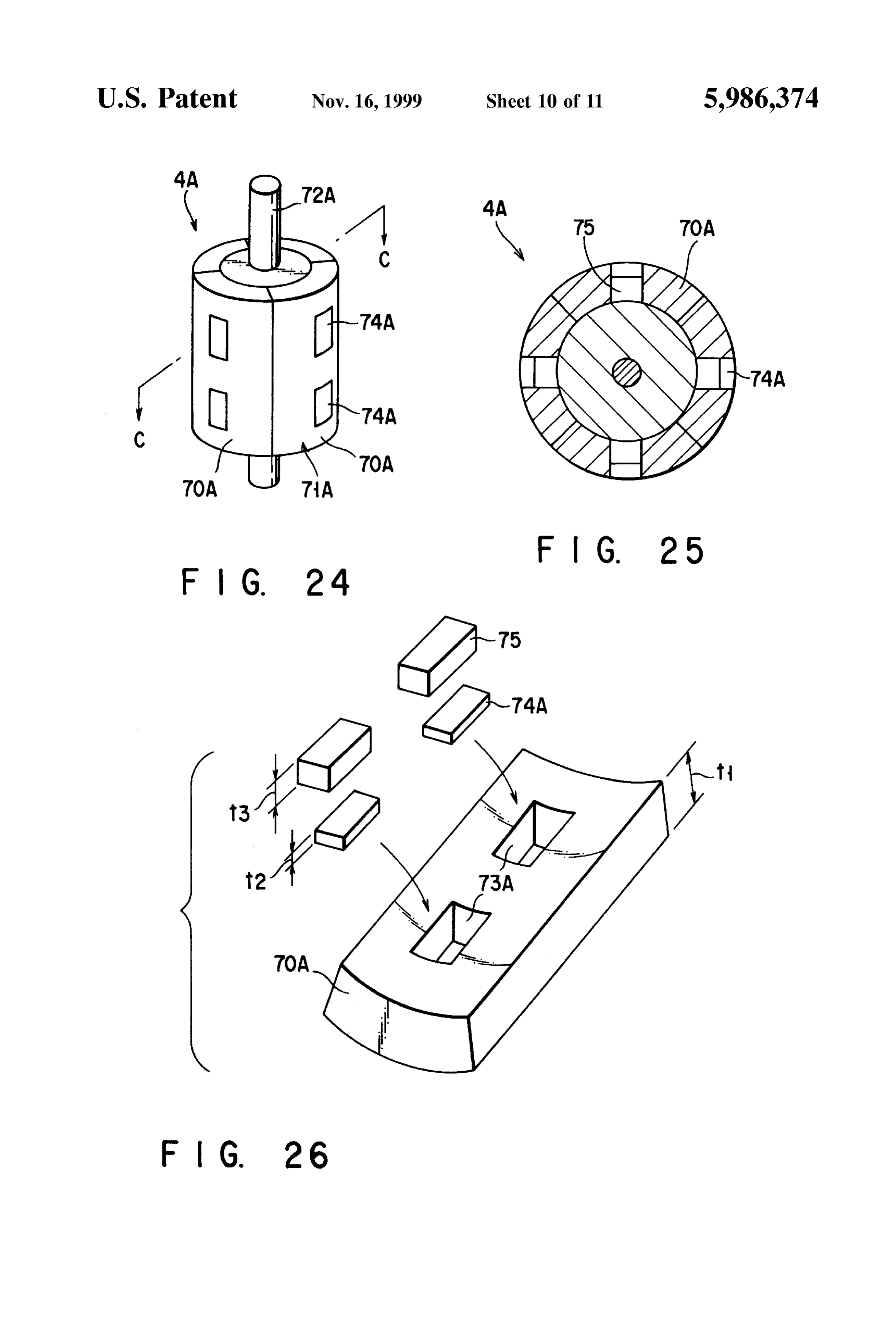
FIG. 14 is a perspective view showing a rotor in a motor mounted in a vehicle; A winding 50 comprised of a coil 18 will be explained FIG. 15 is a croSS-Sectional view, as taken along line below with reference to FIGS. 6 to 8. The winding 50 C-C in FIG. 14; comprises a band-like Section 51 of a length b as a first FIG. 16 is an expanded perspective view showing a longitudinal band-like Section, a connection Section 52 con tinuous with one longitudinal end of the band-like section 51 magnet piece to be fitted in the rotor; 15 and extending in a width direction of the band-like Section
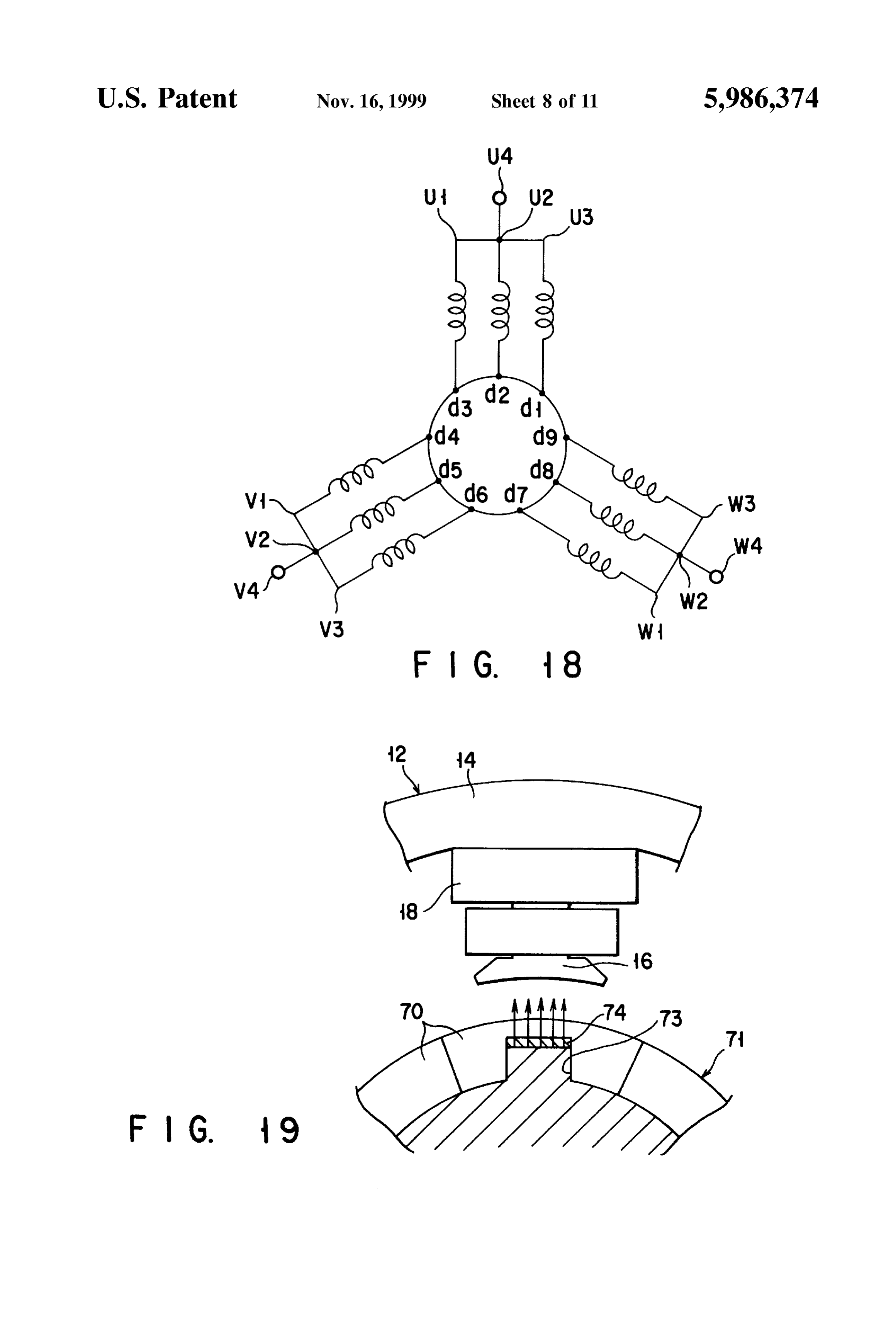
FIG. 17 is an explanatory view showing a state in which 51 from said one longitudinal end and a band-like section 53 a coil is mounted around a projection; as a Second longitudinal band-like Section of a length a (adb) FIG. 18 is an electric connection diagram of the vehicle having the same width as that of the band-like section 51 and motor, extending, at its one end, continuous with the connection FIG. 19 is a cross-sectional view showing part of the section 52. A middle line 54 bisecting the connection section vehicle motor; 52 in a width direction is defined at a middle of the FIG. 20A is a waveform diagram for explaining the projection 16 of the stator 12 as viewed in a right/left magnetic-characteristic of the vehicle motor using a ferrite direction of FIG. 8.
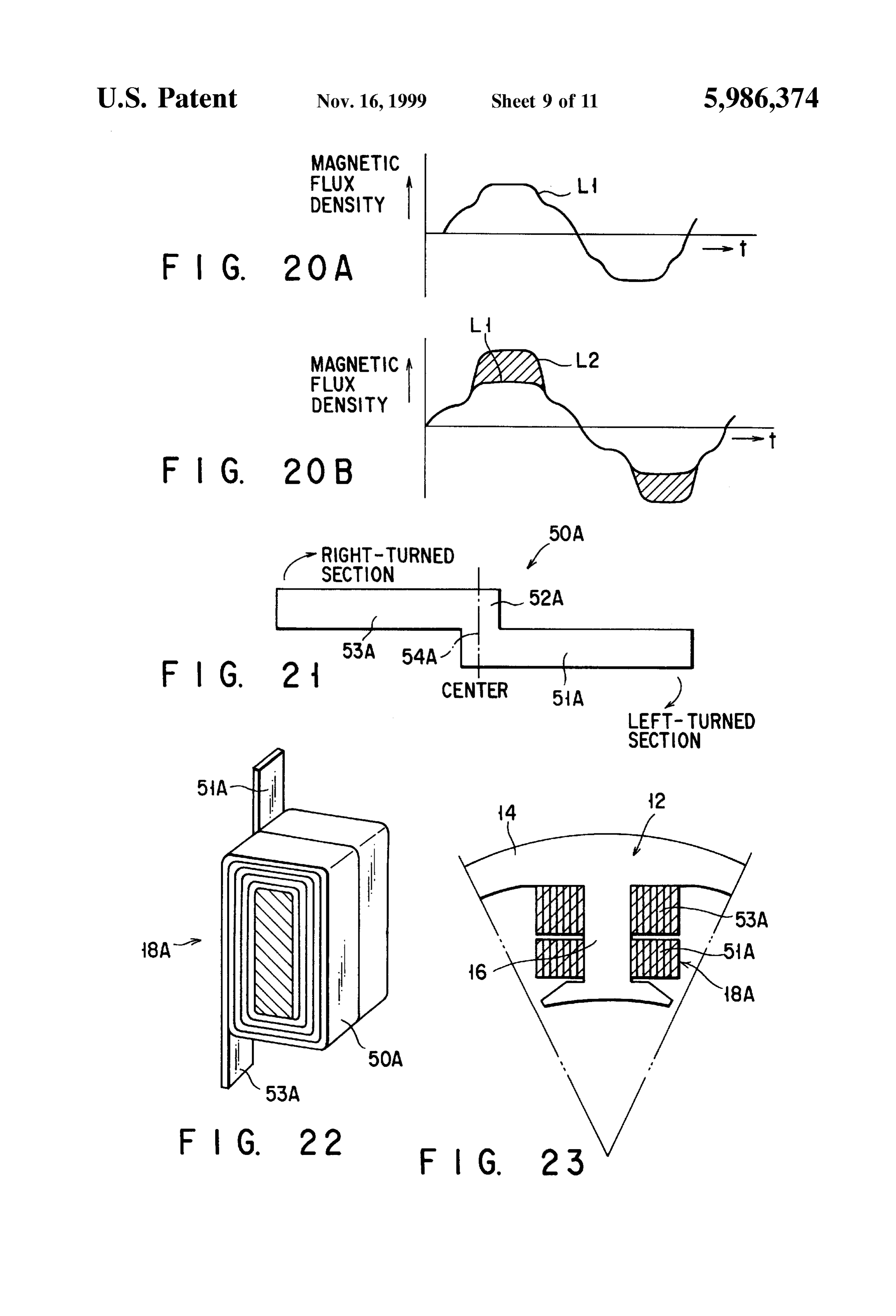
magnet alone; 25 As shown in FIG. 7, the band-like section 51 of the FIG. 20B is a waveform diagram for explaining the winding 50 is wound, as a left-turned Section for instance, magnetic characteristic of the vehicle motor according to the around a radially inward portion of the projection 16 and the embodiment of the present invention; band-like Section 53 is wound, as a right-turned Section for FIG. 21 is an expanded view showing a winding 50A in instance, around a radially outward portion of the projection a first variant of the present invention; 16. In consequence, the end portions of the band-like FIG. 22 is a perspective diagram showing a coil; sections 51 and 53 are exposed to an outside of the coil 18 FIG. 23 is a croSS-Sectional view showing a Stator having with the winding 50 as a turned section as shown in FIG. 7. In this case, for example, the end portion of the band-like a Winding, section 51 is projected upwardly from the coil 18 and the end FIG. 24 is a perspective view showing a rotor 4A in a portion of the band-like section 53 downwardly from the
Second variant of the present embodiment; coil 18.
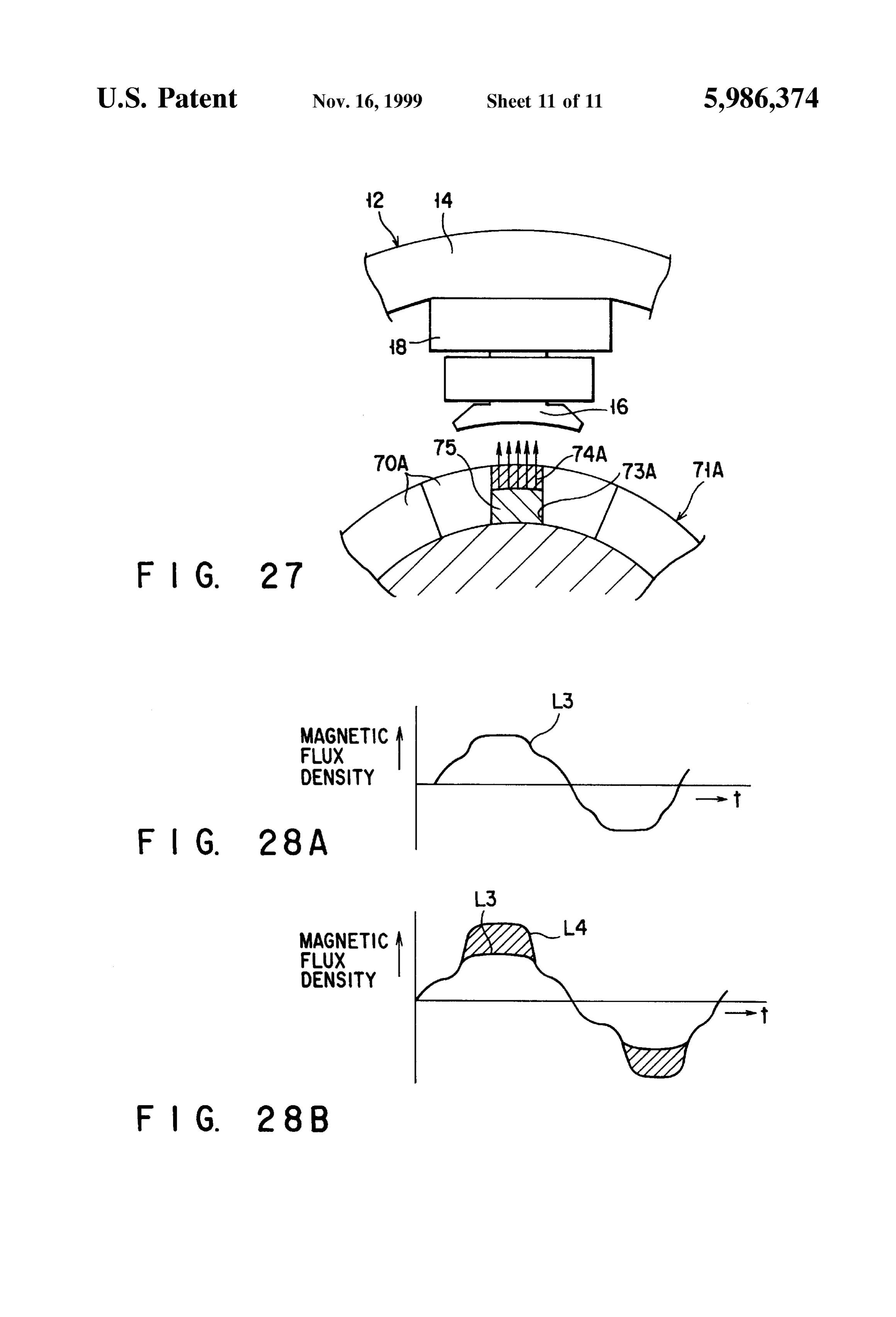
FIG. 25 is a cross-sectional view as taken along C-C in Further, in a Sector area of a unit angle range from the FIG. 24; center of the motor mounted in the vehicle, the length of that FIG. 26 is an exploded, perspective View of magnetic circumferential portion becomes greater in a radially out pieces in the rotor; 40 ward direction and the Space size is increased. AS shown in FIG. 27 is a croSS-Sectional view, as partly taken away, FIG. 8, however, the coil 18 in the winding 50 in the present showing part of the vehicle motor; embodiment is longer at the band-like section 53 than at the FIG. 28A is a waveform diagram for explaining the band-like section 51. For this reason, the projection 13 of the magnetic characteristic of the vehicle motor using a ferrite Stator 12 is made thicker at the radially outward portion than magnet, and 45 at the radially inward portion 55. As a result, the coil 18 is FIG. 28B is a waveform diagram for explaining the So formed as to be thicker in its turned Section in a radially magnetic characteristic of the vehicle motor according to the outward direction. As a result, the Space occupation percent variant of the present invention. age of the winding 50 is increased. Reference numeral 20 of FIG. 5 shows an interconnect
BEST MODE OF CARRYING OUT THE
INVENTION
50 member arranged above the Stator 12. The interconnect member 20 is comprised of, as shown in FIG. 11, a stacked
The embodiment of the present invention will be Structure of first, Second and third connection plates 22, 24 explained below with reference to the accompanying draw and 26 of a regular nonagonal ring-like configuration with ings. FIGS. 4 to 20 show one embodiment of the present the first, Second and third connection plates used for a U-, V invention. 55 and W-phase, respectively.
The arrangement of a motor mounted in a vehicle will be First, explanation will be given below about the structure explained below. The motor 1 is of such a type that it is of the first connection plate 22. The first connection plate 22 mounted in the vehicle, for example, it is a 9-pole motor of comprises an electro-conductive layer 28 formed of a copper three-phases, that is, a U-, V- and W-phase. plate and an insulating layer 30 formed on the electro In a casing 2 of the motor 1, a Stator 12 having a plurality 60 conductive layer 28. On three of those sides of the regular of coils 18 and a rotor 4 are provided with an interconnect nonagonal electro-conductive layer 28, projections U1, U2 member 20 arranged above the stator 12 in FIG. 5 and and U3 are provided at respective 120 angle positions. The having a structure as will be set out below. An interconnect projections U1, U2 and U3 each comprise a horizontal piece member 46 is arranged below the stator 12 in FIG. 5 and has 32 projected in a horizontal direction and an upright pieces a structure as will be set out below. The casing 2 is covered 65 34 raised from the horizontal piece 32. Further, a first with a cover plate 5 and the interconnect member 20 is external terminal projection 38 is projected on one of the connected to a lead wire 36 as will be set out below. sides of the electro-conductive layer 28 to allow the con
Page 16
nection of an external lead wire 36. Crimping portions 40, 40 integral unit. By dosing So, a casing 2 is completed for the are provided on the first external terminal projection 38 to vehicle motor 1 and the forward end portions of the lead allow the lead wire 38 to be crimped therewith (See FIG. wires 36 have their crimped areas (crimped areas 40) 12). mounted with a bush 41 to provide an integral molding unit. The Second connection plate 24 has Substantially the same Fifthly, after the completion of the casing 2, the rotor 4 is Structure as that of the first connection plate 22 and has fitted into a cavity 3 in the casing 2 Such that, by the cover projections V1,V2 and V3 from three of its nine sides. The plate 5, the rotor 4 is rotatably fixed to the casing 2 as shown projecting positions of the projections V1,V2 and V3 are in FIG. 5. In this case, the cover plate 5 is screwed to the displaced relative to those of the counterparts of the first casing 2.
connection plate 22. Further, a Second external terminal Sixthly, as shown in FIG. 9 the lead wire 36 is mounted projection 42 is provided on the Second connection plate to the first external terminal projection 38 (U4 in the electric (See FIG. 12). circuit in FIG. 18). This mounting is achieved with the use The third connection plate 26 has substantially the same of the crimping portions 40 on the first external terminal Structure as the first connection plate 22 and has projections projection 38 corresponding to U4. Similarly, the lead wire W1, W2 and W3 on three of its nine sides. The projecting 15 36 is attached also to the Second external terminal projection positions of these projections W1, W2 and W3 are displaced 42 (V4) and the lead wire 36 is, likewise, mounted to the from those of the counterparts of the first and Second third external terminal projection 44 corresponding to W4. connection plates 22 and 24. Further, a third external ter Then, explanation will be given below about the magne minal projection 44 serves also as the projection W3 (See tizing characteristic of the vehicle motor 1. The trace L1 in FIG. 12). FIG. 20A shows the magnetizing characteristic of the rotor The first, second and third connection plates 22, 24 and 26 in the case of using a ferrite magnet alone and L2 in FIG. are So Stacked as to provide a Stacked inconnect member 20. 20B shows the magnetizing characteristic of the rotor 4 of Reference 46 in FIG. 13 shows a fourth connection plate the present embodiment. FIG. 19 shows the cross-section of one portion of the vehicle motor for which the rotor 4 is (interconnect member) for a neutral point which is disposed 25 used.
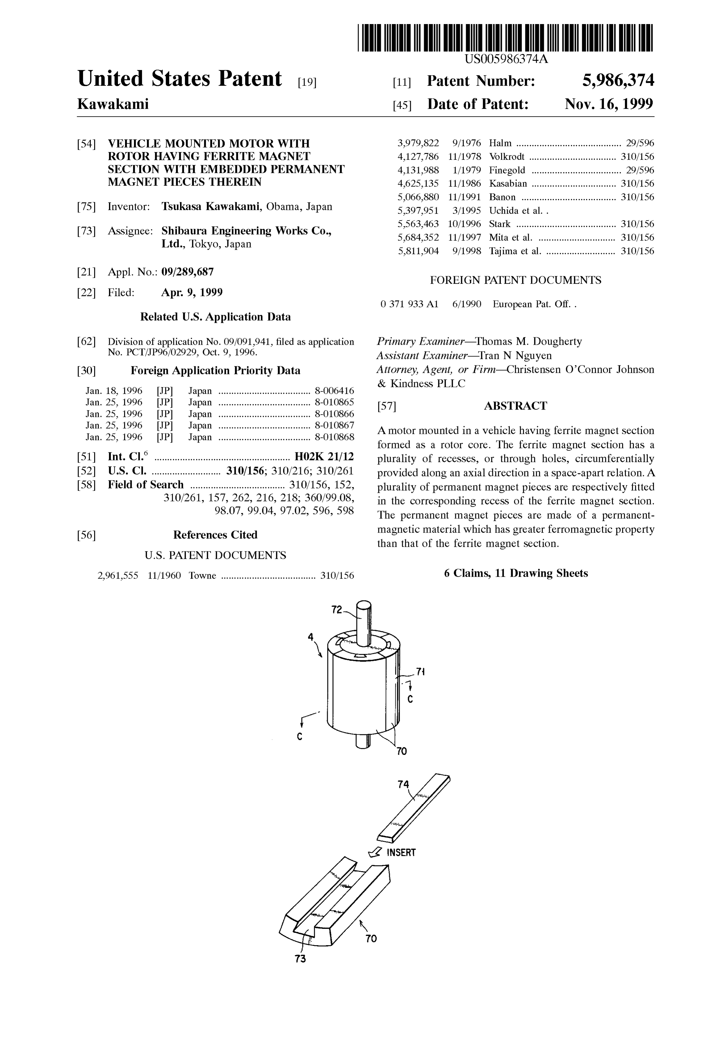
below the stator 12. The fourth connection plate 46 has a the rotator As shown in FIG. 19, the magnetic flux generated from regular nonagonal ring-like configuration and has projec 4 is magnetically coupled to the respective tions dl to d9 each extending from a corresponding one of its projections 16 of the stator 12. In the rotor 4 having such an Sides. arrangement as Set out above, it has been found that, at a On the other hand, the rotor 4 is so formed as to include position of the magnetic piece 74, the magnetic flux gener a cylindrical Section 71 of a permanent magnet into which a conventionalthemagnetic ated from rotor 4 has its density increased over a plurality of Sector-like ferrite-magnet pieces 70 are which is indicated by L1.fluxIn density, as shown in FIG. 20B, consequence, the magnetic flux assembled and a rotation shaft 72 fixed at the center of the cylindrical Section 71. In the respective magnet piece 70, as generated from the rotor 4 has its density increased So that shown in FIG. 16, a groove 73 is formed in a middle inner 35 the vehicle motor 1 can be made to have a high efficiency and a high output power.
wall position along an axial direction in Such a way that, as With the vehicle motor 1 according to the present a magnet piece 74, a magnet material Such as the rare earth invention, Since the Stator 12, interconnect member 20 and magnet greater in magnetic Strength than the ferrite magnet is fitted in, and fixed to, the axial groove 73. The stator 12 unit, even when Suchwith
So on are molded
the molding resin into the integral motor 1 is mounted in the vehicle, the is arranged around the rotor 4 and the rotor 4 is rotated 40 interconnect Section or Sections are prevented from being through a rotational magnetic field in the Stator 12.
The method for assembling the vehicle motor 1 in Sequen possible to obtain excellent vibrationofresistance disconnected by the vibration, etc., the vehicle and it is and impact tial steps will be explained below. resistance. Further, Since the casing 2 of the vehicle motor 1 First, the interconnect member 20 is arranged above the is molded with a molding resin, it is possible to promote a Stator 12 and the fourth connection plate 46 is arranged 45 heat dissipation effect in the vehicle motor 1. below the stator 12. Further, the lower and upper end portions of the winding Second, the upper end portion of the tape-like. coil 18 50 constituting the coil 18 are exposed to an outside of the around the projection 16 of the stator 12 is welded to the coil 18 and the connection operation of the interconnect projections U1, U2, U3, V1,V2, V3 and W1, W2 and W3. 50 members 20, 46 becomes easier. Since a flat band-like As shown in FIG. 17, the end portion of the coil 18 is copper wire is used for the winding 50, no clearance is exposed, as a tape-like portion, to an outside and welded to created between the turned portions of the winding 50 so that and along the upright piece 34 as shown in FIG. 7. By doing it is possible to improve the Space occupation percentage of So, the coil 18 can be readily mounted to the interconnect the winding 50.
member 22. 55 Further, in the Sector area of a unit angle range from the Third, the lower end portion of the coil 18 extending center of the vehicle motor 1, the length of the circumfer downwardly from the projection 16 is exposed as a tape-like ential portion becomes longer in a radially outward direction portion to an outside as in the case of the upper end portion and the Space Size is increased. AS shown in FIG. 8, the coil of the coil 18 and can readily be welded, as in the above 18 of the winding 50 in the present embodiment is so formed case, to the respective places of the respective projections d1 60 as to be made longer at the band-like section 51 than at the to d9 of the fourth connection plate 46. band-like section 53. For this reason, the thickness of the The interconnection of the respective coils 18 of the stator radially outward portion of the projection 13 of the stator 12 12 is achieved along the arrangement of an electric circuit as is greater than that of the radially inward section 55 thereof shown in FIG. 18. So that it is possible to increase the Space occupation Fourthly, after the assembling of these components, the 65 percentage of the winding 50.
stator 12, coils 18, interconnect member 20 and fourth Since use is made of the rare earth magnet Stronger in connection plate 46 are molded with a molding resin into an ferromagnetic property than the ferrite magnet material, the
Page 17
density of a magnetic flux produced from the rotor 4 is Explanation will be given below about the rotor 4A. The increased So that the vehicle motor 1 can be made higher in trace L3 in FIG. 28A shows the magnetic characteristic of its efficiency and its output power. In this case, although the the rotor when only the ferrite magnet is used and the L4 in rare earth magnet is higher in cost than the ferrite magnet FIG. 28B shows the magnetic characteristic of the rotor 4A material, it is partly used for the cylindrical section 56 so thatin the present embodiment. FIG. 19 is a cross-sectional view, it incurs no larger additional cost in the vehicle motor 1. AS partly taken away, showing a portion of a vehicle motor 1 a result, the rare earth magnet not readily available in view using the rotor 4A. As shown in FIG. 27, a magnetic flux of its high cost can be effectively used according to the created from the rotor 4A is magnetically coupled to the present invention. For this reason, it is possible to manu respective projection 16 of the stator 12. In the rotor 4A facture the vehicle motor 1 at less cost by that extent. having the arrangement as Set out above, it has been found A first variant of the above-mentioned embodiment will that, at the position of the magnet piece 74A, the density of be explained below with reference to the drawings. In the the magnetic flux created from the rotor 4A is increased over present variant, a coil 18A is used in place of the coil 18 as the line L3 representing the magnetic flux density of the shown in FIGS. 21 to 23. prior art as shown in FIG.20B.
A winding 50A constituting the coil 18A is comprised of 15 Even in the present variant, the density of the magnetic a flat band-like copper wire and comprises a band-like density created from the rotor 4A is increased and it is Section 51A as a first longitudinal band-like Section, a possible to achieve the high efficiency and high output connection Section 52A continuous with one longitudinal power on the vehicle motor. Further, although the rare earth end of the band-like Section and extending in a width magnet higher in ferromagnetic property than the ferrite direction of the band-like section 51A from said one longi magnet material is high in cost, Since the magnet piece 74A tudinal end and a band-like Section 53A as a Second longi made of the rare earth magnet is partly used simply to an tudinal band-like Section having the same width as that of extent to be fitted in the through hole 73A in the cylindrical the band-like Section 51A and extending, at its one end, Section 71A, the use of it in the vehicle motor 1 incurs no continuous with the connection section 52A. A middle line greater extra cost and, further, it is possible to readily and 54A bisecting the connection section 52A in a width direc 25 effectively use the rare earth magnet relatively hard to get in tion is defined at a middle of a projection 16 of the Stator as terms of cost. Still further, the thickness t2 of the magnet viewed in a right/left direction of FIG. 23. piece 74A is made smaller than the thickness t1 of the As shown in FIG. 22, the band-like Section 51A of the magnet pieces 74A So that less amount of rare earth magnet winding 50A is wound, as a left turned Section for instance, can be used readily and effectively. around a radially inward portion of the projection 16 and the I claim:
band-like Section 53A is wound, as a right-turned Section for 1. A motor mounted in a vehicle, having a rotor compris instance, around a radially outward portion of the projection ing a permanent magnet Section formed as a cylindrical 16. In consequence, the end portions of the band-like Section, made of a ferrite magnet material and having a sections 51A and 53A are exposed to an outside of the coil 35 plurality of recesses circumferentially provided along an 18A in the winding 50A as shown in FIG. 22. In this case, axial direction in a Space-apart relation in an inner Surface of the end portion of the band-like section 51A is so formed as the cylindrical Section and magnet pieces made of a perma to be projected, for example, upwardly from the coil 18A nent magnet material greater in ferromagnetic property than and the end portion of the band-like portion 53 A to be the ferrite magnet material and each fitted in the correspond projected, for example, downwardly from the coil 18A. 40 ing receSS in the permanent magnetic Section. Even in the present variant, the upper and lower end 2. The motor according to claim 1, wherein the permanent portions of the winding 50A constituting the coil 18A are magnetic Section has a plurality of magnetic poles along its exposed to an outside of the coil 18A and it is easier to peripheral Surface and the receSS is provided at a middle of achieve the connection operation of the interconnect mem each magnetic pole.
bers 20, 46 as set out above. 45 3. A motor mounted in a vehicle, having a rotor compris A Second variant of the above-mentioned embodiment ing a permanent magnet Section formed as a cylindrical will be explained below with reference to the associated Section from a ferrite magnet material and having a plurality drawings. In the present variant, a rotor 4A is used, in place of through holes circumferentially provided in an inner of the rotor 4 as shown in FIGS. 24 to 26. Surface in a Spaced-apart relation along an axial direction The rotor 4A comprises a cylindrical section 71A of a 50 and permanent magnet pieces greater in ferromagnetic prop permanent magnet Section into which a plurality of Sector erty than the ferrite magnet material and each fitted in the corresponding through hole in the permanent magnetic like magnet pieces 70A of a thickness ti are assembled and Section.
a rotation shaft 72A fixed at the center of the cylindrical
Section 71A, the Sector-like magnet piece being made of a 4. The motor according to claim3, wherein the permanent ferrite magnet. In a middle position of the inner wall Surface 55 magnet Section has a plurality of magnetic poles along its of the respective magnet piece 70A, two through holes 73 circumferential Surface and the through hole provided at a for example are formed at a given interval along the axis of middle position of the magnetic pole. the cylindrical section 71A and a magnet piece 74A of a 5. The motor according to claim 3, wherein the through thickness t2 (t1dt2) fitted in, and fixed to, the through hole holes are provided at a plurality of places in a Spaced-apart relation along the axial direction of the permanent magnet and made of a magnetic material Such as a rare earth magnet 60 greater in magnetic Strength than the ferrite magnet. A yoke Section.
75 of a thickness t3 (t1>t3, t1=t2+t3) is fitted in the through piece6. The motor according to claim 3, wherein the magnet hole in a radially inward direction relative to the magnet is made thinner than the permanent magnet Section and piece 54A and made of a magnetic material, Such as iron. a yoke made of a magnetic material and arranged in a The stator 12 is arranged around the rotor 4A and allows the 65 radially inward direction.
rotor to be rotated under a rotation magnetic field from the stator 12.
Provenance
- Collection
- Cited prior art
- Original PDF
- patentimages.storage.googleapis.com →
- Filed
- 1999-04-09
- Pages
- 17
- Method
- pdftotext (the PDF's own text layer) + pdftoppm 300dpi page scans
- Source
- Google Patents bibliographic record
- Granted
- 1999-11-16
- Inventors
- Tsukasa Kawakami; Shibaura Engineering Works Co Ltd
- Transcribed from
- patentimages.storage.googleapis.com →