patent · US5091668
Motor having flux-concentrating permanent magnets
25 February 1992
Page 1 — bibliographic record
United States Patent (19) 11 Patent Number: 5,091,668 Cuenot et al. (45) Date of Patent: Feb. 25, 1992 (54) MOTOR HAVING FLUX-CONCENTRATING FOREIGN PATENT DOCUMENTS
PERMANENT MAGNETS
(75) Inventors: Alain Cuenot; Bouziane Bendahmane, 0327470 8/1989 European Pat. Off. . both of Dijon, France
OTHER PUBLICATIONS
(73) Assignee: GEC ALSTHOM S.A, Paris, France
Patent Abstracts of Japan, vol. 12, No. 476 (21) Appl. No.: 625,192 (E-693)(3323) Dec. 13, 1988, & JP-A-63 194550 22 Filed: Dec. 10, 1990 (FANUC) Aug. 11, 1988. (30) Foreign Application Priority Data Primary Examiner-R. Skudy Dec. 8, 1989 FR) France .......................... 89.6251
Attorney, Agent, or Firm-Sughrue, Mion, Zinn,
Macpeak & Seas (51) Int. C. ............................................ H02K 21/12 57 ABSTRACT (52) U.S.C. ...................................... 310/156; 310/91;
310/181; 310/217; 310/218 A motor having flux-concentrating permanent magnets, 58) Field of Search ................................ 310/216-218, the motor including a stator with windings and a rotor 310/156, 261, 265, 91, 42, 264, 181, 265, 270; including a shaft, a sleeve surrounding the shaft for 464/29; 336/210 holding rotor laminations, and permanent magnets. The 56) References Cited motor being characterized in that said sleeve is consti tuted by unitary sleeves (2) separated by disks (5), the
2,680,822 6/1954 Brainard .............................. 310/261 (6) connected to at least one end cheek plate (7) which 3,659,129 4/1972 Pettersen ... is fixed to the shaft (1).
4,403,161 9/1983 Miyashita ............................ 310/156 8 Claims, 3 Drawing Sheets
as 6. RNZZNNNa
Page 2
Drawing sheet — no readable text.
Page 3
Drawing sheet — no readable text.
Page 4
Drawing sheet — no readable text.
Page 5
In a preferred embodiment, the unitary sleeves sur
MOTOR HAVING FLUX-CONCENTRATING round the shaft with a small amount of clearance. PERMANENT MAGNETS In a variant, the unitary sleeves surround the shaft with a small amount of clearance and are fixed thereto
FIELD OF THE INVENTION by means of tolerance rings.
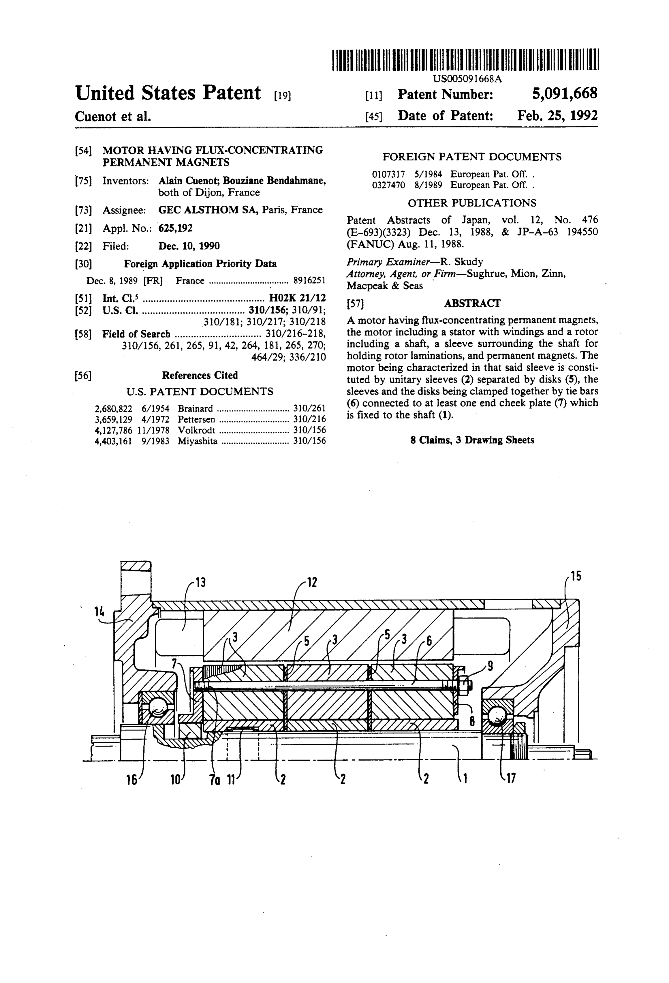
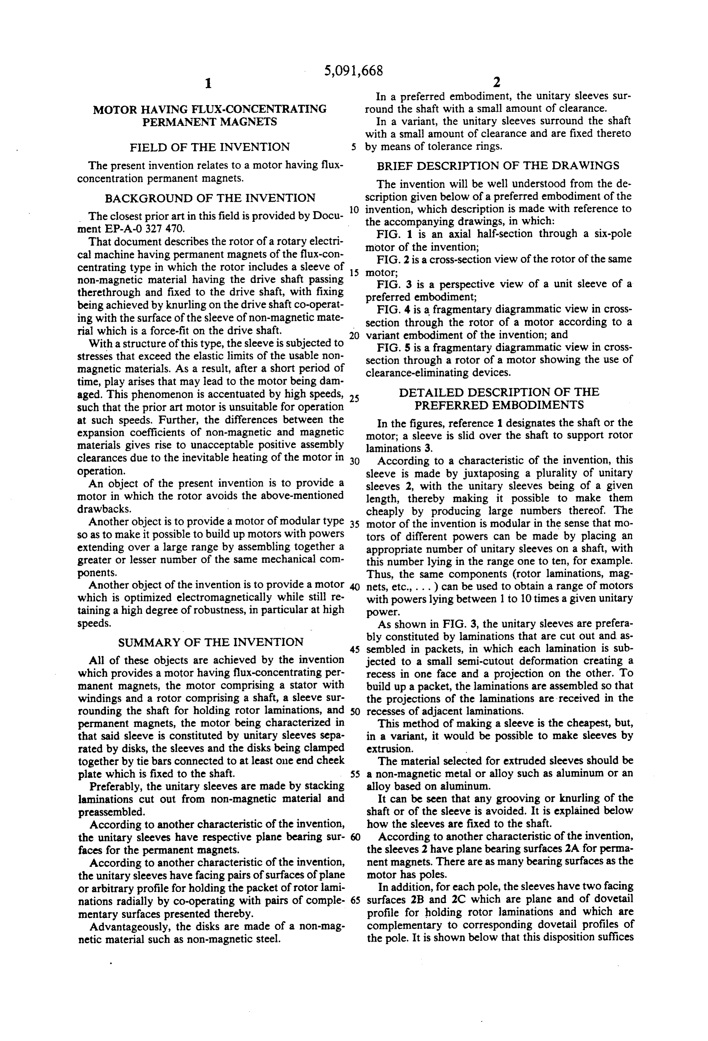
The present invention relates to a motor having flux BRIEF DESCRIPTION OF THE DRAWINGS concentration permanent magnets. The invention will be well understood from the de BACKGROUND OF THE INVENTION scription given below of a preferred embodiment of the O invention, which description is made with reference to
The closest prior art in this field is provided by Docu the accompanying drawings, in which: ment EP-A-0 327 470. FIG. 1 is an axial half-section through a six-pole That document describes the rotor of a rotary electri cal machine having permanent magnets of the flux-con motor of the invention;
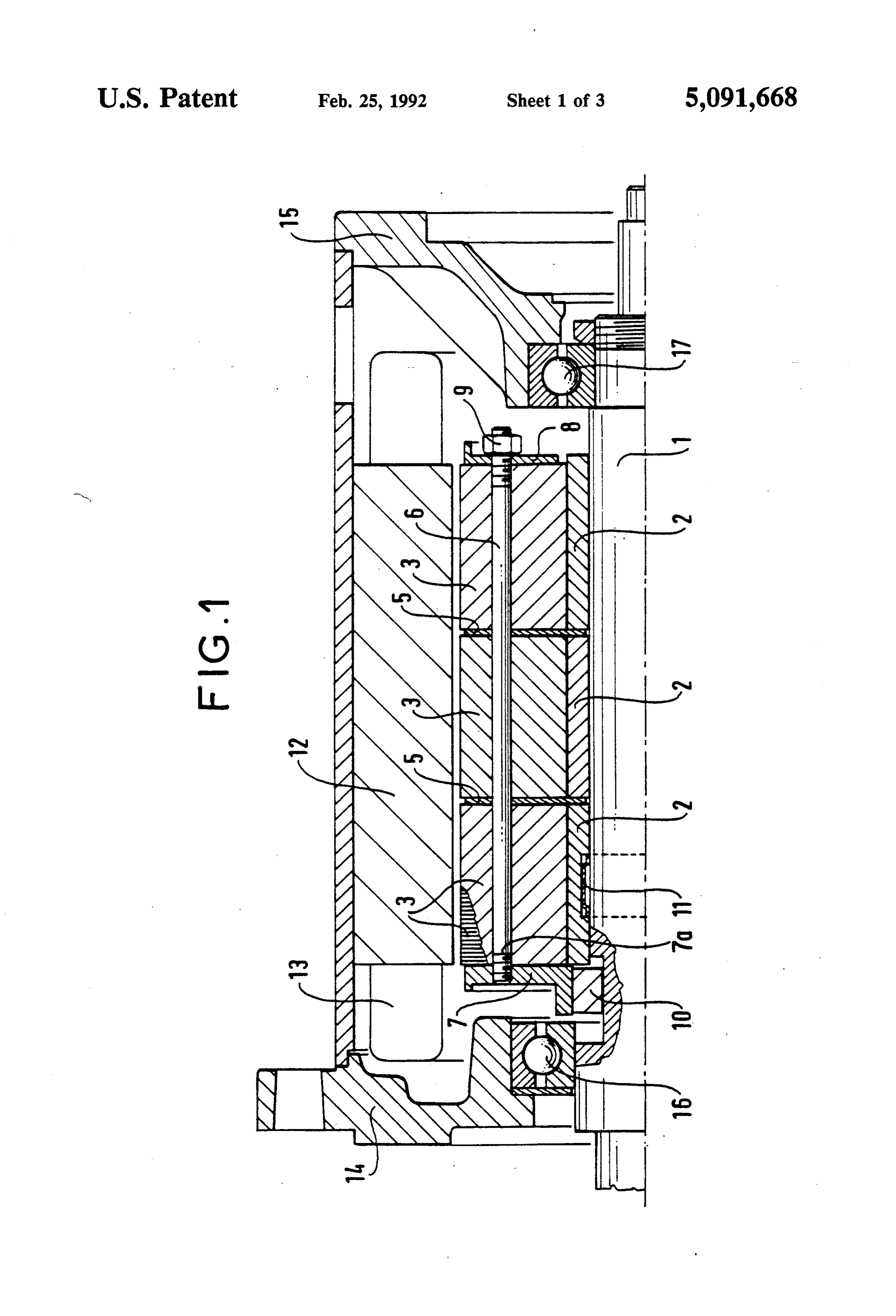
FIG. 2 is a cross-section view of the rotor of the same centrating type in which the rotor includes a sleeve of 15 motor;
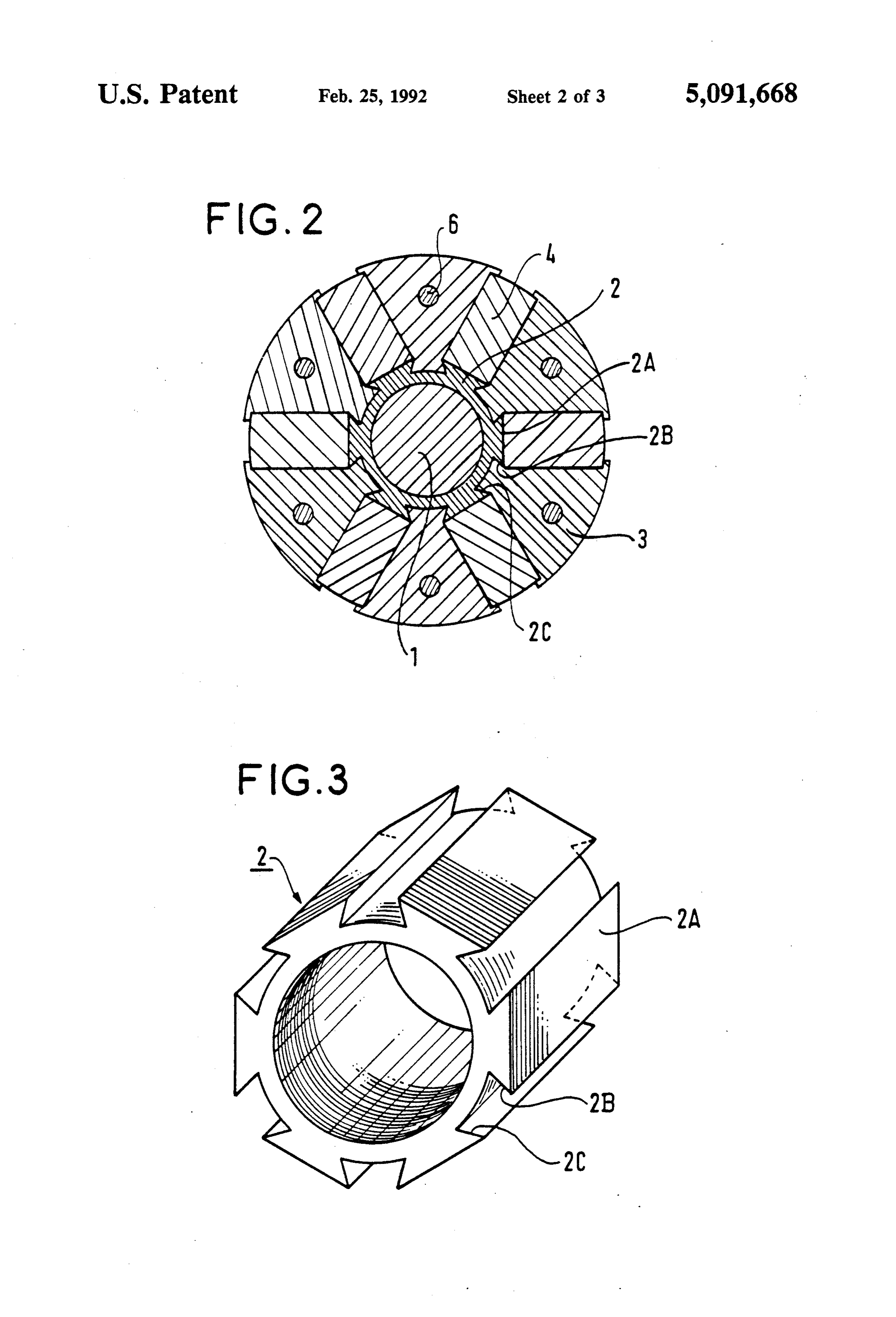
non-magnetic material having the drive shaft passing FIG. 3 is a perspective view of a unit sleeve of a therethrough and fixed to the drive shaft, with fixing preferred embodiment;
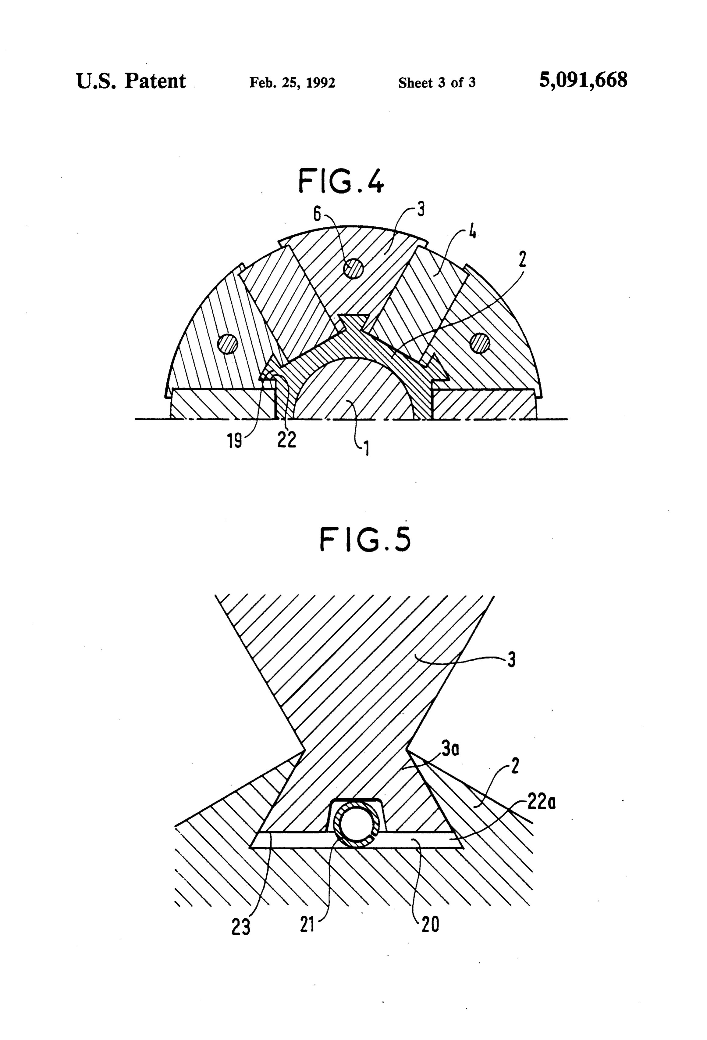
being achieved by knurling on the drive shaft co-operat FIG. 4 is a fragmentary diagrammatic view in cross ing with the surface of the sleeve of non-magnetic mate section through the rotor of a motor according to a rial which is a force-fit on the drive shaft. 20
With a structure of this type, the sleeve is subjected to variant
FIG.
embodiment of the invention; and 5 is a fragmentary diagrammatic view in cross stresses that exceed the elastic limits of the usable non section through a rotor of a motor showing the use of magnetic materials. As a result, after a short period of clearance-eliminating devices.
time, play arises that may lead to the motor being dam aged. This phenomenon is accentuated by high speeds, 25 DETAILED DESCRIPTION OF THE such that the prior art motor is unsuitable for operation PREFERRED EMBODIMENTS at such speeds. Further, the differences between the In the figures, reference 1 designates the shaft or the expansion coefficients of non-magnetic and magnetic motor; a sleeve is slid over the shaft to support rotor materials gives rise to unacceptable positive assembly laminations 3.
clearances due to the inevitable heating of the motor in 30 According to a characteristic of the invention, this operation. sleeve is made by juxtaposing a plurality of unitary An object of the present invention is to provide a sleeves 2, with the unitary sleeves being of a given motor in which the rotor avoids the above-mentioned length, thereby making it possible to make them drawbacks. cheaply by producing large numbers thereof. The Another object is to provide a motor of modular type 35 motor of the invention is modular in the sense that no so as to make it possible to build up motors with powers tors of different powers can be made by placing an extending over a large range by assembling together a appropriate number of unitary sleeves on a shaft, with greater or lesser number of the same mechanical con this number lying in the range one to ten, for example. ponents. Thus, the same components (rotor laminations, mag Another object of the invention is to provide a motor 40 nets, etc., . . . ) can be used to obtain a range of motors which is optimized electromagnetically while still re with powers lying between 1 to 10 times a given unitary taining a high degree of robustness, in particular at high power.
speeds. As shown in FIG. 3, the unitary sleeves are prefera SUMMARY OF THE INVENTION bly constituted by laminations that are cut out and as 45 sembled in packets, in which each lamination is sub
All of these objects are achieved by the invention jected to a small semi-cutout deformation creating a which provides a motor having flux-concentrating per recess in one face and a projection on the other. To manent magnets, the motor comprising a stator with build up a packet, the laminations are assembled so that windings and a rotor comprising a shaft, a sleeve sur the projections of the laminations are received in the rounding the shaft for holding rotor laminations, and SO recesses of adjacent laminations. permanent magnets, the motor being characterized in This method of making a sleeve is the cheapest, but, that said sleeve is constituted by unitary sleeves sepa in a variant, it would be possible to make sleeves by rated by disks, the sleeves and the disks being clamped extrusion.
together by tie bars connected to at least one end cheek The material selected for extruded sleeves should be plate which is fixed to the shaft. 55 a non-magnetic metal or alloy such as aluminum or an Preferably, the unitary sleeves are made by stacking alloy based on aluminum.
laminations cut out from non-magnetic material and It can be seen that any grooving or knurling of the preassembled. shaft or of the sleeve is avoided. It is explained below According to another characteristic of the invention, how the sleeves are fixed to the shaft. the unitary sleeves have respective plane bearing sur 60 According to another characteristic of the invention, faces for the permanent magnets. the sleeves 2 have plane bearing surfaces 2A for perma According to another characteristic of the invention, nent magnets. There are as many bearing surfaces as the the unitary sleeves have facing pairs of surfaces of plane motor has poles.
or arbitrary profile for holding the packet of rotor lami In addition, for each pole, the sleeves have two facing nations radially by co-operating with pairs of comple surfaces 2B and 2C which are plane and of dovetail mentary surfaces presented thereby. profile for holding rotor laminations and which are Advantageously, the disks are made of a non-mag complementary to corresponding dovetail profiles of netic material such as non-magnetic steel. the pole. It is shown below that this disposition suffices
Page 6
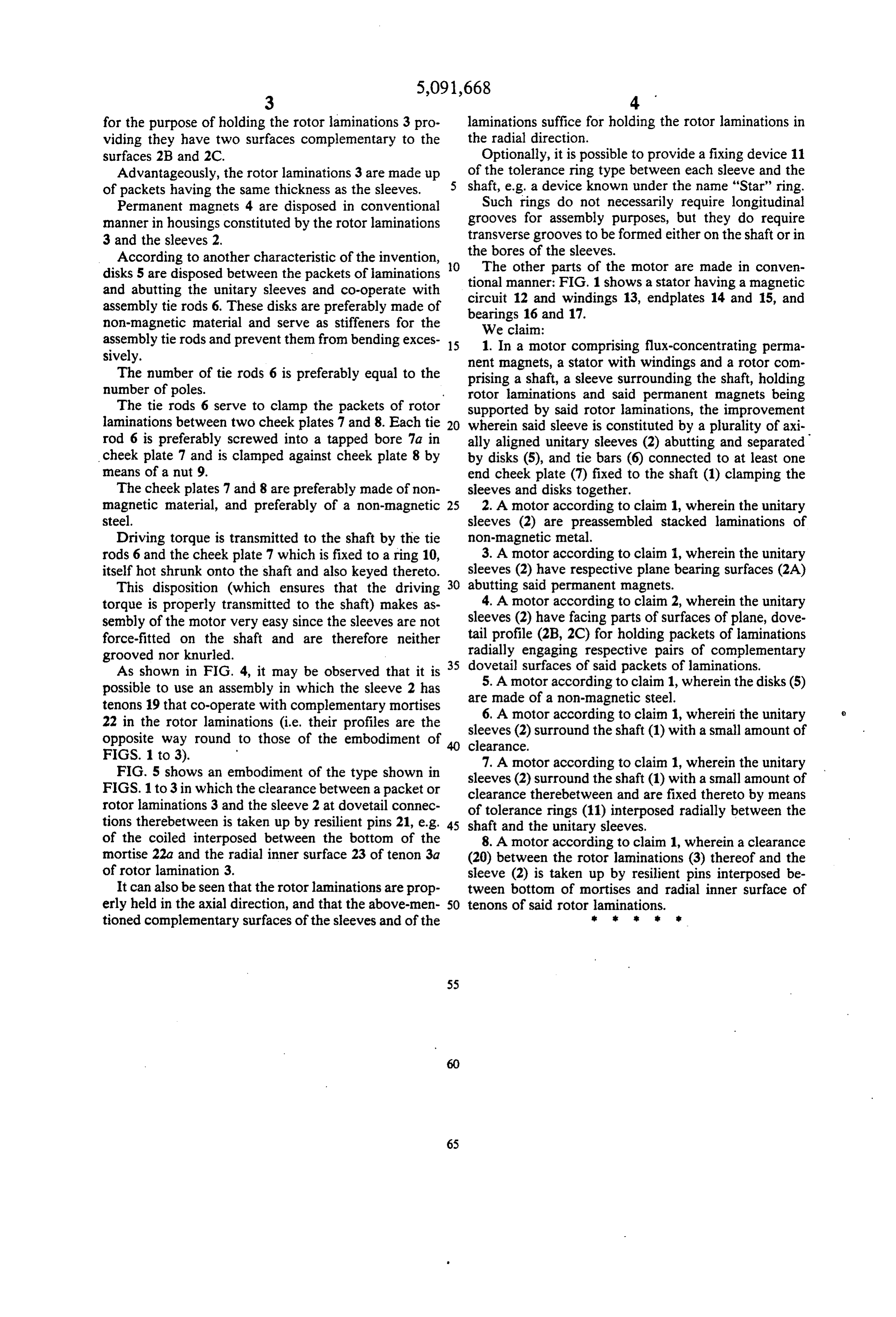
for the purpose of holding the rotor laminations 3 pro laminations suffice for holding the rotor laminations in viding they have two surfaces complementary to the the radial direction.
surfaces 2B and 2C. Optionally, it is possible to provide a fixing device 11 Advantageously, the rotor laminations 3 are made up of the tolerance ring type between each sleeve and the of packets having the same thickness as the sleeves. shaft, e.g. a device known under the name "Star' ring. Permanent magnets 4 are disposed in conventional Such rings do not necessarily require longitudinal manner in housings constituted by the rotor laminations grooves for assembly purposes, but they do require 3 and the sleeves 2. transverse grooves to be formed either on the shaft or in the bores of the sleeves.
According to another characteristic of the invention, disks 5 are disposed between the packets of laminations O The other parts of the motor are made in conven and abutting the unitary sleeves and co-operate with tional manner; FIG. 1 shows a stator having a magnetic assembly tie rods 6. These disks are preferably made of bearings1216and circuit and windings 13, endplates 14 and 15, and
non-magnetic material and serve as stiffeners for the We claim:
assembly tie rods and prevent them from bending exces 15 1. In a motor comprising flux-concentrating perma sively. nent magnets, a stator with windings and a rotor com The number of tie rods 6 is preferably equal to the prising a shaft, a sleeve surrounding the shaft, holding number of poles. rotor laminations and said permanent magnets being The tie rods 6 serve to clamp the packets of rotor supported by said rotor laminations, the improvement laminations between two cheek plates 7 and 8. Each tie 20 wherein said sleeve is constituted by a plurality of axi rod 6 is preferably screwed into a tapped bore 7a in ally aligned unitary sleeves (2) abutting and separated cheek plate 7 and is clamped against cheek plate 8 by by disks (5), and tie bars (6) connected to at least one means of a nut 9. end cheek plate (7) fixed to the shaft (1) clamping the The cheek plates 7 and 8 are preferably made of non sleeves and disks together.
magnetic material, and preferably of a non-magnetic 25 2. A motor according to claim 1, wherein the unitary steel. sleeves (2) are preassembled stacked laminations of Driving torque is transmitted to the shaft by the tie non-magnetic metal.
rods 6 and the cheek plate 7 which is fixed to a ring 10, 3. A motor according to claim 1, wherein the unitary itself hot shrunk onto the shaft and also keyed thereto. sleeves (2) have respective plane bearing surfaces (2A) This disposition (which ensures that the driving 30 abutting said permanent magnets.
torque is properly transmitted to the shaft) makes as 4. A motor according to claim 2, wherein the unitary sembly of the motor very easy since the sleeves are not sleeves (2) have facing parts of surfaces of plane, dove force-fitted on the shaft and are therefore neither tail profile (2B, 2C) for holding packets of laminations grooved nor knurled. radially engaging respective pairs of complementary As shown in FIG. 4, it may be observed that it is 35 dovetail surfaces of said packets of laminations. possible to use an assembly in which the sleeve 2 has are5.made
A motor according to claim 1, wherein the disks (5) of a non-magnetic steel.
tenons 19 that co-operate with complementary mortises 6. A motor according to claim 1, whereini the unitary 22 in the rotor laminations (i.e. their profiles are the sleeves (2) surround the shaft (1) with a small amount of opposite way round to those of the embodiment of 40 clearance.
FIGS. 1 to 3). 7. A motor according to claim 1, wherein the unitary FIG. 5 shows an embodiment of the type shown in sleeves (2) surround the shaft (1) with a small amount of FIGS. 1 to 3 in which the clearance between a packet or clearance therebetween and are fixed thereto by means rotor laminations 3 and the sleeve 2 at dovetail connec of tolerance rings (11) interposed radially between the tions therebetween is taken up by resilient pins 21, e.g. 45 shaft and the unitary sleeves. of the coiled interposed between the bottom of the 8. A motor according to claim 1, wherein a clearance mortise 22a and the radial inner surface 23 of tenon 3a (20) between the rotor laminations (3) thereof and the of rotor lamination 3. sleeve (2) is taken up by resilient pins interposed be It can also be seen that the rotor laminations are prop tween bottom of mortises and radial inner surface of erly held in the axial direction, and that the above-men 50 tenons of said rotor laminations. tioned complementary surfaces of the sleeves and of the 2
Provenance
- Collection
- Cited prior art
- Original PDF
- patentimages.storage.googleapis.com →
- Filed
- 1990-12-10
- Pages
- 6
- Method
- pdftotext (the PDF's own text layer) + pdftoppm 300dpi page scans
- Source
- Google Patents bibliographic record
- Granted
- 1992-02-25
- Inventors
- Alain Cuenot; Bouziane Bendahmane; GEC Alsthom SA
- Transcribed from
- patentimages.storage.googleapis.com →