patent · US4336649
Method of making rotor assembly having anchor with undulating sides
29 June 1982
Page 1 — bibliographic record
United States Patent (19) 11 4,336,649 Glaser (45) Jun. 29, 1982 (54) METHOD OF MAKING ROTOR ASSEMBLY 56) References Cited
HAVING ANCHOR WITHUNDULATING
SIDES U.S. PATENT DOCUMENTS 902,019 10/1908 Sulzberger .......................... 310/156 (75) Inventor: Jerry Glaser, Playa del Rey, Calif. 2,033,059 3/1936 Williamson ......................... 310/156 2,719,931 10/1955 Kober .................................. 310/156 73 Assignee: The Garrett Corporation, Los 2,739,253 3/1956 Plumb ............................... 310/42 X 3,083,311 3/1963 Krasnow ............................. 310/156
Angeles, Calif. 3,237,034 2/1966 Krasnow ............................. 310/156 4,117,360 9/1978 Richter ................................ 310/156 21 Appl. No.: 138,019 FOREIGN PATENT DOCUMENTS 22) Filed: Apr. 7, 1980 2659650 11/1978 Fed. Rep. of Germany . Primary Examiner-Carl E. Hall
Related U.S. Application Data Attorney, Agent, or Firm-Fay I. Konzem; Albert J. Miller
51 Int. Cl. ............................................. H02K 15/02 A rotor assembly having wedge-shaped permanent 52) U.S. C. ...................................... 29/598; 310/153; magnets and anchors with undulating sides for attach 310/156 ing the rotor hub to the pole bodies.
310/156, 261, 262, 42, 43, 218 4 Claims, 5 Drawing Figures
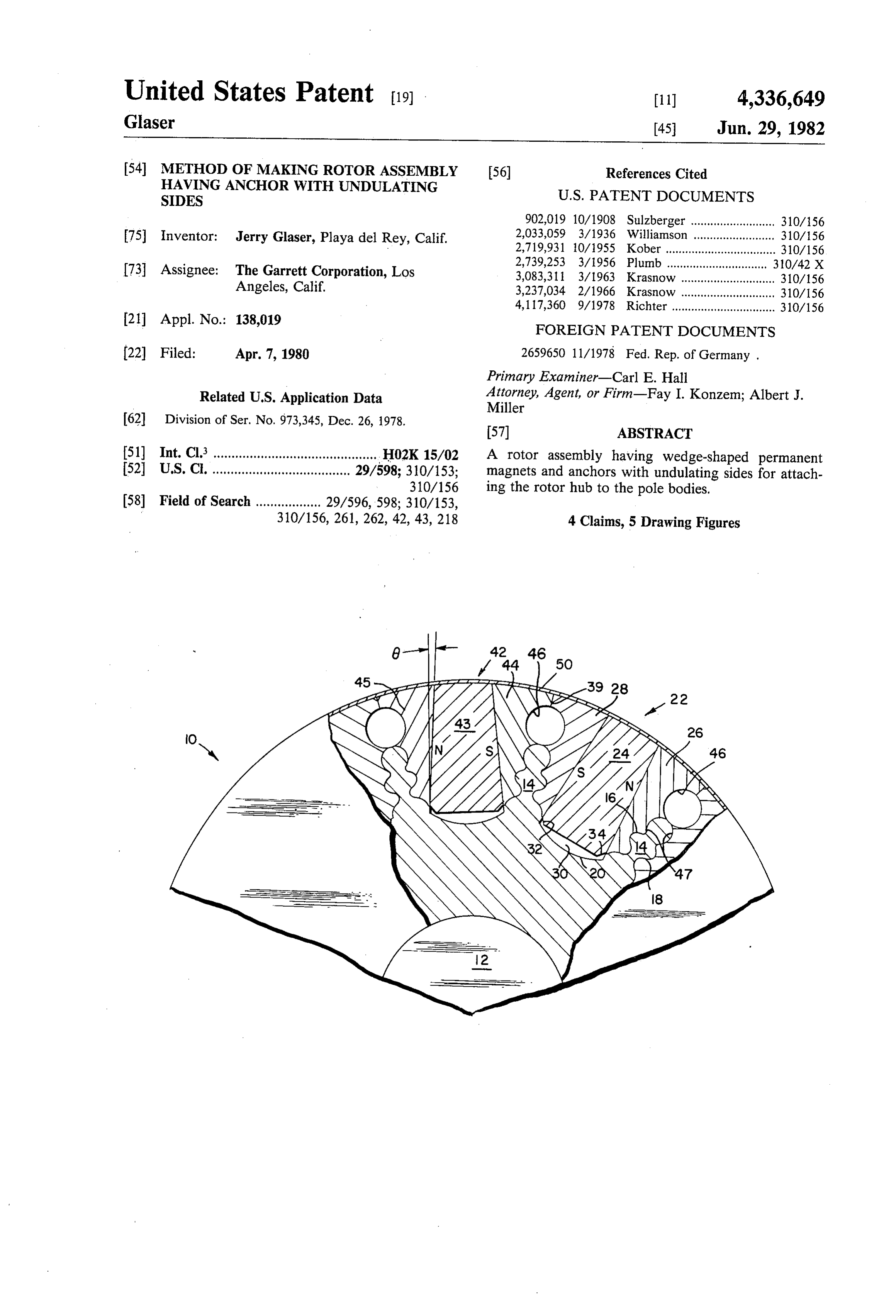
Page 2
Drawing sheet — no readable text.
Page 3
Drawing sheet — no readable text.
Page 4
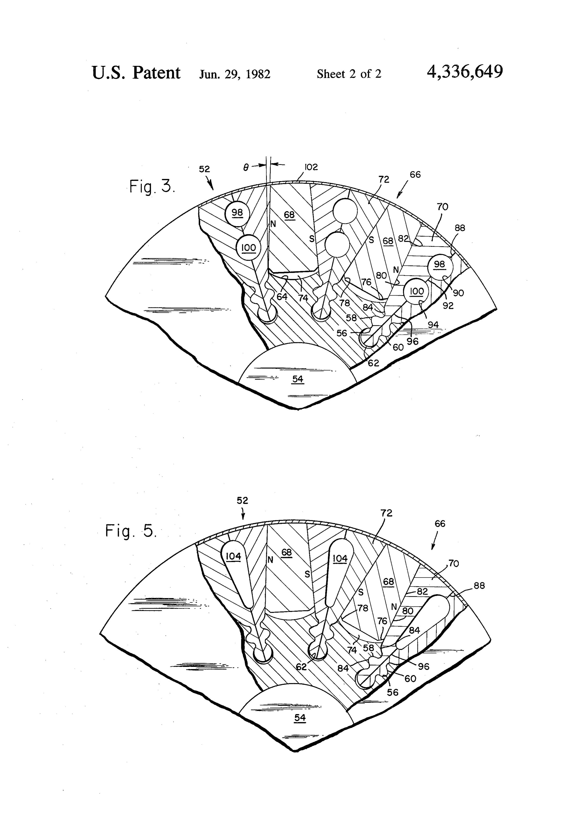
FIG. 5 shows a variation of the rotor assembly of
METHOD OF MAKING ROTOR ASSEMBLY FIG. 3.
HAVING ANCHOR WITH UNDULATING SIDES
DETAILED DESCRIPTION OF THE
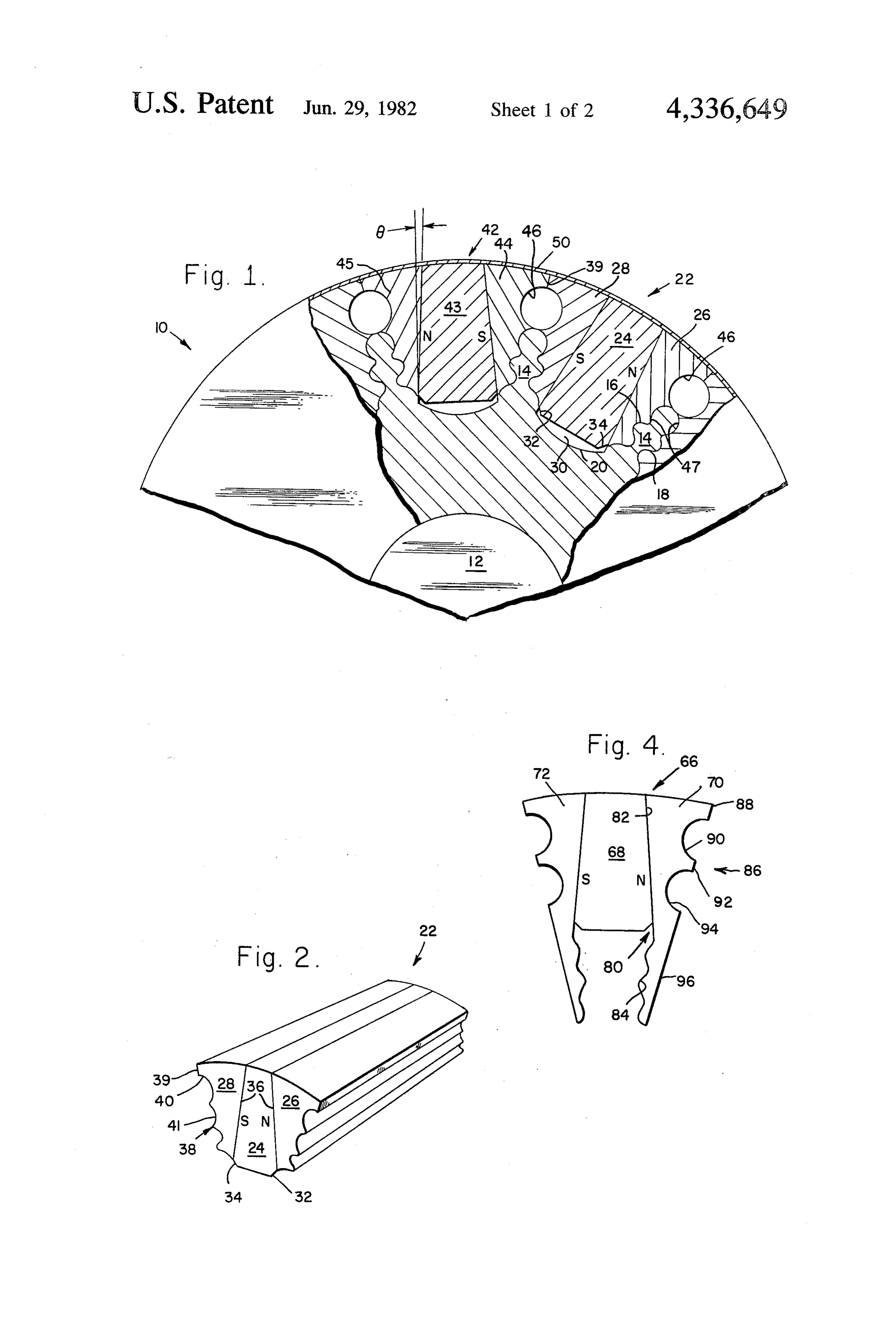
This is a division of application Ser. No. 973,345 filed PREFERRED EMBODIMENT Dec. 26, 1978. Referring now to FIG. 1, a permanent magnet rotor BACKGROUND OF THE INVENTION assembly 10 includes a generally cylindrical hub 12 with a plurality of equally spaced tongues 14 radially extend
This invention relates to subject matter disclosed in ing outward around the periphery thereof. The tongues
26, 1978, entitled "Wedge-Shaped Permanent Magnet 18. Disposed between each pair of adjacent tongues 14 Rotor Assembly' by Frederick B. McCarty and Alex on the outer periphery of the hub 12 is a concave recess ander Silver, now U.S. Pat. No. 4,242,610; Ser. No. 20. The hub 12 consists of a non-magnetic material. 973,344 entitled "Rotor Assembly Having Rectangu A magnet-support member assembly 22 is located larly Shaped Tongues', by Alexander Silver, now U.S. 15 between each pair of the undulating tongues 14 and Pat. No. 4,260,921; and Ser. No. 973,343, filed Dec. 26, around the periphery on the hub 12. The assembly 22 1978, entitled "Rotor Assembly with Magnet Cush consists of an outwardly converging wedge-shaped ions', by Frederick B. McCarty, Alexander Silver and permanent magnet 24 with identical support members Lyman R. Burgmeier, now U.S. Pat. No. 4,302,693, 26 and 28 affixed to either side of the magnet 24. The each of which are assigned to the same assignee as this 20 support material.
members 26 and 28 consist of a ferromagnetic application.
This invention relates to high speed permanent mag The outwardly converging wedge-shaped permanent net rotor assemblies, and more particularly, to rotor magnets 24 are shorter in length than the distance from assemblies having wedge-shaped permanent magnets 25 the base of the recess 20 to the outer periphery of the and anchors with undulating sides for attaching the pole rotor assembly 10 thereby forming a gap 30 between the bodies to the rotor's hub. base of the magnet 24 and the base of the recess 20. The In the art, methods have been developed to join the purpose of the gap is to facilitate assembly, and to cool non-magnetic hub to the magnetic pole pieces in a rotor the rotor 10 the rotor by permitting cooling air to flow through assembly. The base of the magnets 24 may assembly. One such method is the hot isostatic pressure 30 have
(HIP) bonding process which is performed under ex magnetslant corners 32 and 34 for easy insertion of the 24 into the recess 20.
treme pressure (circa 18,000 p.s.i.a.) and at elevated The size of the angle formed between the sides of the temperatures (circa 2200 F). Another method used to magnets 24 and a plane parallel to a central radius join the non-magnetic and magnetic rotor materials through the magnet is critical and should be slightly less together is furnace brazing, which is also performed at 35 than the angle elevated temperatures (circa 1860°F). The brazing and determined andofis friction.
the
This angle is experimentally maximum angle at which a lock
(HIP) bonding techniques do not permit optimizing the ing wedge action is achieved for the heat treatment of the structural steel parts for maximum tions pertinent to a given design. If thematerial and condi angle is too large strength. The resultant brazed/bonded structure is not the magnets will not remain locked in place after the as strong as it could be. 40 rotor ceases to rotate and if the angle is too small, lateral SUMMARY OF THE INVENTION crushing forces may cause the magnet to fracture. The permanent magnet rotor assembly, in accordance locking anglethere
Therefore, is a critical range within which the with the invention, includes outwardly converging of the locking angle 0 lie.
6 must It has been found that the size wedge-shaped permanent magnets retained between 45 preferably 6 to 8 degrees. be between 2 to 9 degrees, should inwardly converging wedge-shaped support members. FIG. 2 is a perspective view showing the magnet-sup The rotor hub and support members are attached by port member assembly 22. The inwardly converging means of anchors with undulating sides. wedge-shaped support members 26 and 28 have a A principal advantage of the present invention is that smooth side 36 which fits flush against the magnet 24. A the magnets are held in place between the support mem 50 second side 38 of the support members has a flat surface bers by their wedge-shape. Also, the rotor hub is at 39, a semi-circular groove 40, and an undulating portion tached to the support members by means of anchors 4.
with undulating sides so that the non-magnetic hub and Adjacent the magnet-support member assembly 22 is the magnetic support members or pole bodies are me a second magnet-support member assembly 42 which chanically joined without the need for the high temper 55 includes an outwardly converging wedge-shaped per ature brazing or high pressure (HIP) bonding methods manent magnet 43 and inwardly converging wedge of joining the two dissimilar materials, thereby main shaped support members 44 and 45 affixed to either side taining the structural integrity of the materials. of the magnet 43. The magnet-support member assem BRIEF DESCRIPTION OF THE DRAWINGS bly 42 is identical to the assembly 22. A plurality of such 60 assemblies are located around the outer periphery of the
FIG. 1 is a cross-section view of the rotor assembly of hub 12.
the present invention. When the rotor 10 is assembled, the side 38 of the FIG. 2 is a perspective drawing showing the magnet support member 28 is in contact with the support mem and support member assembly of FIG. 1. ber 44 at the flat surface 39, thereby forming a circular FIG. 3 illustrates an alternate embodiment of the 65 hole 46 and a groove 47 with undulating sides. The rotor assembly of the present invention. circular hole 46 reduces the rotor's mass and allows air FIG. 4 shows the magnet-support member assembly to flow through the rotor 10 to reduce the surface tem of FIG. 3. perature thereof. The undulating portions of the sup
Page 5
port members 28 and 44 form a groove 47 which inter have slant corners 76 and 78 for easy insertion of the locks around the undulating sides 16 and 18 of the magnets 68 into the recess 64.
tongues 14, The undulating sides 16 and 18 of the FIG. 4 is a cross-section view showing the magnet tongue 14 allow more surface area to be in contact with support member assembly 66 of FIG. 3. The inwardly the support members 28 and 44 than a smooth sided converging wedge-shaped support members 70 and 72 tongue would; therefore, the tongues 14 with undulat have a side 80 with a smooth section 82, fitting flush ing sides are superior in retention of the support mem against the side of the magnet 68 and an undulating bers. Also, no high stress concentration is present in the section 84 extending beyond the base of the magnet 68. undulating sides 16 and 18 of the tongues 14 because of the curvilinearity of the sides as opposed to sides with O The having support members 70 and 72 have another side 86 a flat or smooth portion 88, a semi-circular sharp corners. groove 90, a flat portion 92, another semi-circular A thin hoop 50 which is heat shrunk upon the periph groove 94 and a flat portion 96.
ery of the magnets and support members functions as an Referring to both FIGS. 3 and 4, when the rotor 52 is electric damper to intercept and diminish the flux har assembled, the flat portions 88, 96, and 96 of the support monics caused by the stator and penetrating into the 15 support members and the magnets. Reflecting eddy members of their 70 and 72 make contact with the flat portions adjacent support members (as described for currents are produced in the hoop 50, thereby shielding FIGS. 1 and 2) thereby forming circular holes 98 and the permanent magnets and the support members. The 100. The holes 98 and 100 reduce the rotor's mass and hoop 50 has a minor structural function, providing a allow air to flow through the rotor assembly 52 to re retaining force over the peripheral contact with the 20 duce the surface temperature thereof. The holes formed magnets and the support members. This retaining force is small and merely supplemental to the retaining pro between the support members can be of a variety of shapes, the circular holes 98 and 100 as shown in FIG.
vided by the hub 12. The hoop 50 consists of a high strength, non-magnetic material preferably having a 3shown are easier to fabricate than the oblong-shaped holes in FIG. 5. The oblong-shaped holes remove low resistivity, such as a beryllium copper alloy. 25 more mass from the rotor assembly and therefore a The rotor 10 is constructed by first affixing one side higher tip speed limit results. The size and location of of the magnet 24 to the side 36 of the support member the holes is established with regard to magnetic and 26 and the other side of the magnet 24 to the side 36 of structural considerations.
the support member 28 by means of an adhesive. Next, The smooth sections 82 of the side 80 of the support the side 38 of the support members 26 and 28 is ma 30 members 70 and 72 is in contact with the magnet 68 and chined to form the semi-circular groove 40 and the the undulating section 84 which extends past the base of undulating portion 41. Next, the magnet-support mem the magnet 68 and interlocks with the undulating sides ber assembly 22 is inserted between the tongues 14 and 58 and 60 of the groove 56.
the outer peripheral surface of the magnets 24 and the A thin electrically dampening hoop 102 is shrunk support members 26 and 28 are ground so that the sur 35 around the periphery of the rotor assembly 52. The faces smoothly blend. Finally, the hoop 50 is shrunk hoop 102 consists of a non-magnetic material such as a around the outer periphery of the magnet-support mem beryllium copper alloy.
ber assemblies 22. The rotor assembly 52 of FIGS. 3 and 5 is con It is difficult to machine accurate wedge-shaped mag structed by first affixing one side of the magnet 68 to the nets and their mating grooves because of the brittle smooth section 82 of the side 80 of the support member nature of the magnet material and the errors in machin 70 and the other side of the magnet 68 to the smooth ing a wedge-shaped port and cavity. By first machining section 82 of the side 80 of the support member 72 by the magnet 24 and then affixing the support members 26 means of an adhesive. Next, the undulating section 84 of and 28 to the sides of the magnet 24 the shape of the the side 80 is machined along with the semi-circular support members 26 and 28 (namely, the outer edge 38) 45 grooves 90 and 94 on the side 86 of the support mem can be precisely machined since the support members bers 70 and 72. Then, the magnet support member as consist of a ferromagnetic material. semblies 66 are inserted around the outer periphery of FIGS. 3 and 4 show a permanent magnet rotor assem the hub 54, with the undulating sections 84 of the sup bly 52 which includes a generally cylindrical hub 54 port members 70 and 72 interlocking into the grooves with a plurality of equally spaced grooves 56. The SO of the hub 54. The outer peripheral surface of the grooves 56 have undulating sides 58 and 60 terminating 56 magnets 68 and the support members 70 and 72 are in a base 62. The hub 54 also has a plurality of concave ground so that the surfaces smoothly blend. Finally, the recesses 64 located between the adjacent grooves 56. hoop 102 is shrunk around the outer periphery of the The hub 54 consists of a non-magnetic material. magnet-support member assemblies. A plurality of magnet-support member assemblies 66 55 While specific embodiments of the invention have are located around the outer periphery of the hub 54. been illustrated and described, it is to be understood that The assembly 66 consists of an outwardly converging these embodiments are provided by way of example wedge-shaped permanent magnet 68 with identical sup only and the invention is not to be construed as being port members 70 and 72 affixed to either side of the limited thereto, but only by the proper scope of the magnet 68. 60 following claims:
The outwardly converging wedge-shaped permanent What is claimed is:
magnets are shorter in length than the distance from the 1. A method of forming a rotor for a permanent mag base of the recess 64 to the outer periphery of the rotor net machine, comprising the steps of: assembly 10, thereby forming a gap 74 between the base forming a non-magnetic rotor hub having a plurality of the magnet 68 and the base of the recess 64. The 65. of equally spaced, radially extending tongues with purpose of the gap is to facilitate assembly, and to cool undulating sides;
the rotor 10 by permitting cooling air to flow through forming a plurality of assemblies of a wedge-shaped the rotor assembly. The base of the magnets 68 may tangentially magnetized permanent magnet having

Page 6
outwardly converging sides between a pair of magnet and having an outwardly disposed gener wedge-shaped ferromagnetic support members, ally smooth side and an opposite side having a each of said support members having a smooth side smooth portion secured to the permanent magnet secured to the permanent magnet and an opposite and a radially inwardly projecting undulating por side having a radially outer smooth portion and a 5 tion; and radially inner undulating portion; and inserting the radially inward projecting portions of inserting a formed assembly between the radially the formed assembly into adjacent grooves of the extending
smooth of theofFG portions hub assemblies adjacent with Silly in rotor hub, the smooth outwardly disposed sides of contact and the radially inner undulating portions 10 adjacent assemblies forming a tongue having undu cooperating with the corresponding undulating lating sides cooperative with the undulating sides sides of the radially extending tongues. of a groove.
2. A method of forming a rotor for a permanent mag- 3. The method of claim 1 or 2 wherein the sides of the net machine, comprising the steps of: individual permanent magnets form an angle within the forming a non-magnetic rotor hub having a plurality 15 range of 2-9 degrees with a plane parallel to the rotor of equally spaced, inwardly extending grooves radius through the center line of said individual perma with undulating sides; nent magnet.
forming a plurality of assemblies of a wedge-shaped 4. The method of claim 1 or 2 wherein the sides of the tangentially magnetized permanent magnet having individual permanent magnets form an angle within the outwardly converging sides between a pair of 20 range of 6-8 degrees with a plane parallel to the rotor wedge-shaped ferromagnetic support members, radius through the center line of said individual perma each of said support members extending radially nent magnets.
inwardly beyond the wedge-shaped permanent sk k k sk sk
Provenance
- Collection
- Cited prior art
- Original PDF
- patentimages.storage.googleapis.com →
- Filed
- 1980-04-07
- Pages
- 6
- Method
- pdftotext (the PDF's own text layer) + pdftoppm 300dpi page scans
- Source
- Google Patents bibliographic record
- Granted
- 1982-06-29
- Inventors
- Jerry Glaser; Garrett Corp
- Transcribed from
- patentimages.storage.googleapis.com →