patent · US5280209
Permanent magnet structure for use in electric machinery
18 January 1994
Page 1 — bibliographic record
United States Patent (19) 11) Patent Number: 5,280,209 Leupold et al. (45) Date of Patent: Jan. 18, 1994
(54) PERMANIENT MAGNET STRUCTURE FOR
FOREIGN PATENT DOCUMENTS
USE IN ELECTRIC MACHINERY
(75) Inventors: Herbert A. Leupold, Eatontown; 0177903 8/1987 Japan ........ ... 335/301 Ernest Potenziani, II, Ocean, both of O763984 9/980 U.S.S.R. ................... ... 335/209 N.J. 956938 4/1964 United Kingdom................ 310/154
73) Assignee: The United States of America as Primary Examiner-Steven L. Stephan represented by the Secretary of the Assistant Examiner-Clayton E. LaBalle
Army, Washington, D.C. Attorney, Agent, or Firm-Michael Zelenka; John M.
22) Filed: Nov. 14, 1989 Magnetically rigid materials are utilized to enhance the (51) Int. Cl...................... H02K 21/26; HO2K 21/12; field magnitudes produced by permanent magnet struc H01F 7/02 tures that are utilized in electric machinery. Magnetic (52) U.S. C. .................................... 310/156; 310/154; circuit losses due to unnecessary magnetic fields are 335/306 eliminated without employing a conventional shunt.
58) Field of Search ....................... 335/301, 209,306; The magnetically rigid material is cylindrically config 310/46, 152, 154, 156 ured and magnetized to provide individual magnetic fields between sets of north and south poles on only one (56) References Cited cylindrical surface thereof. At least one coaxial cylinder
permanent magnet structure of the invention and each
H 693 10/1989 Leupold .............................. 335/306 of the cylinders is constructed from a plurality of seg 3,168,686 2/1965 King et al. .. ... 335/306 ments in one preferred embodiment thereof. Segments 3,205,415 9/1965 Seki et al. ............................ 335/301 having a substantially triangular cross-sectional config 3,334,254 8/1967 Kober .................................. 30/156 uration are utilized in other preferred embodiments, 3,768,054 10/1973 Neugebauer ........................ 335/306 while flux contributions from at least three segments 4,645,961 2/1987 Malsky ................................ 310/156 4,839,059 6/1989 Leupold ...... ... 335/30 combine to sustain each set of north and south poles in 4,862,128 8/1989 Leupold .............................. 335/306 still other preferred embodiments. 4,893,103 1/1990 Leupold ...... ... 335/306 5,013,951 5/1991 Stadnik ................................ 310/56 6 Claims, 4 Drawing Sheets
Page 2
Drawing sheet — no readable text.
Page 3
Drawing sheet — no readable text.
Page 4
Drawing sheet — no readable text.
Page 5
Drawing sheet — no readable text.
Page 6
and through the inner cylindrical surface of the cylin
PERMANENT MAGNET STRUCTURE FOR USE IN ders when the permanent magnet structure is for incor ELECTRIC MACHINERY poration on stators. Each cylinder is constructed from a plurality of magnetized segments in the preferred em
The invention described herein may be manufac bodiments of the invention. These segments may have tured, used, and licensed by or for the Government for various cross-sectional configurations which in the pre governmental purposes without payment to us of any ferred embodiments are only disclosed as substantially royalties thereon. triangular. Otherwise, the configuration of these seg BACKGROUND OF THE INVENTION ments may extend parallel to the longitudinal axis of the cylinder for various distances which in the preferred
The present invention relates generally to permanent embodiments are only disclosed as the full length magnet structures and more particularly, to those struc thereof.
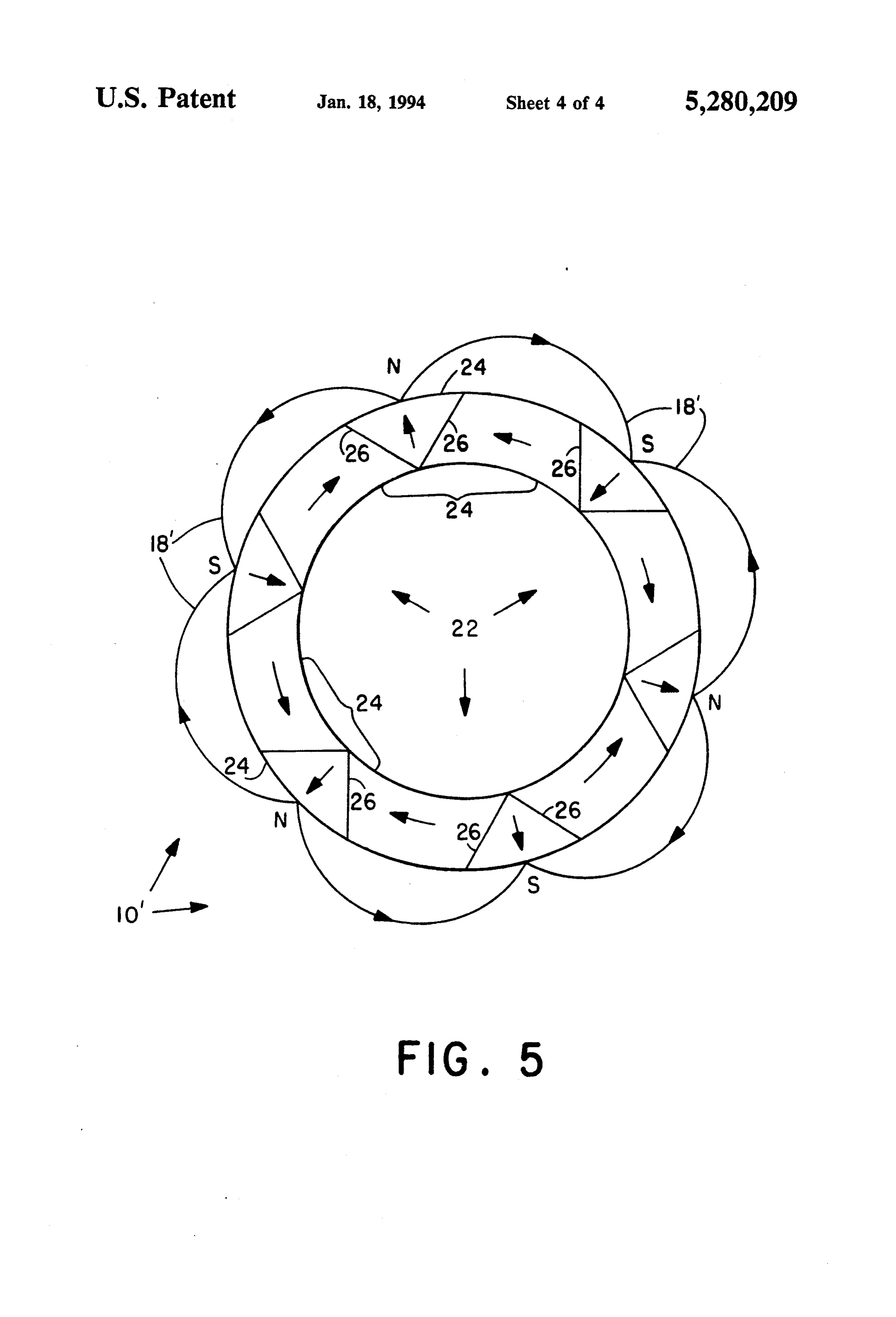
tures which are utilized in electric machinery such as The scope of the present invention is only limited by motors and generators. the appended claims for which support is predicated on As is well known in the art of electric machinery, the 15 the preferred embodiments hereinafter set forth in the flux density of conventional permanent magnet struc following description and the attached drawings tures is less than optimal due to various magnetic losses. wherein like reference characters relate to like parts The most common magnetic losses encountered with throughout the several figures.
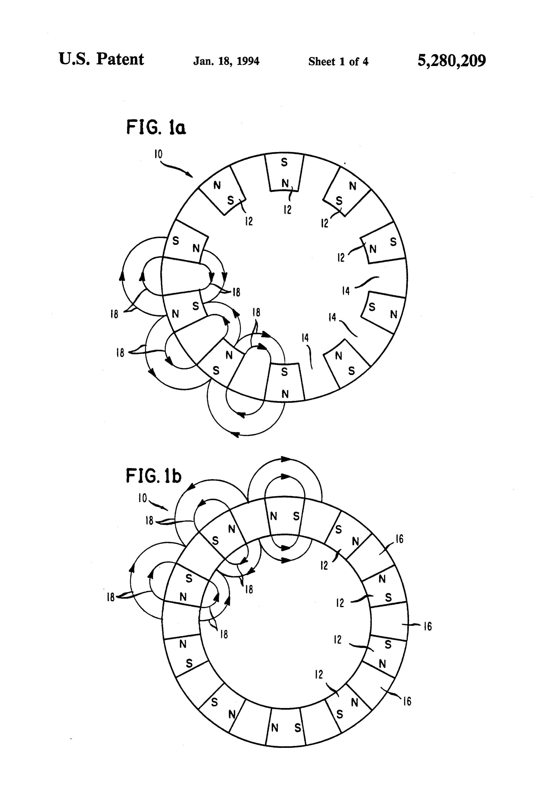
permanent magnet structures in electric machinery are DESCRIPTION OF THE DRAWINGS due to flux leakage or unnecessary reluctance in the magnetic circuit thereof. When, traditional magnetic FIGS. 1a, 1b, 1c, are end views of permanent magnet materials, such as Alnico, are utilized in these perma structures which are commonly found in electric ma nent magnet structures, adjacently disposed north and chinery;
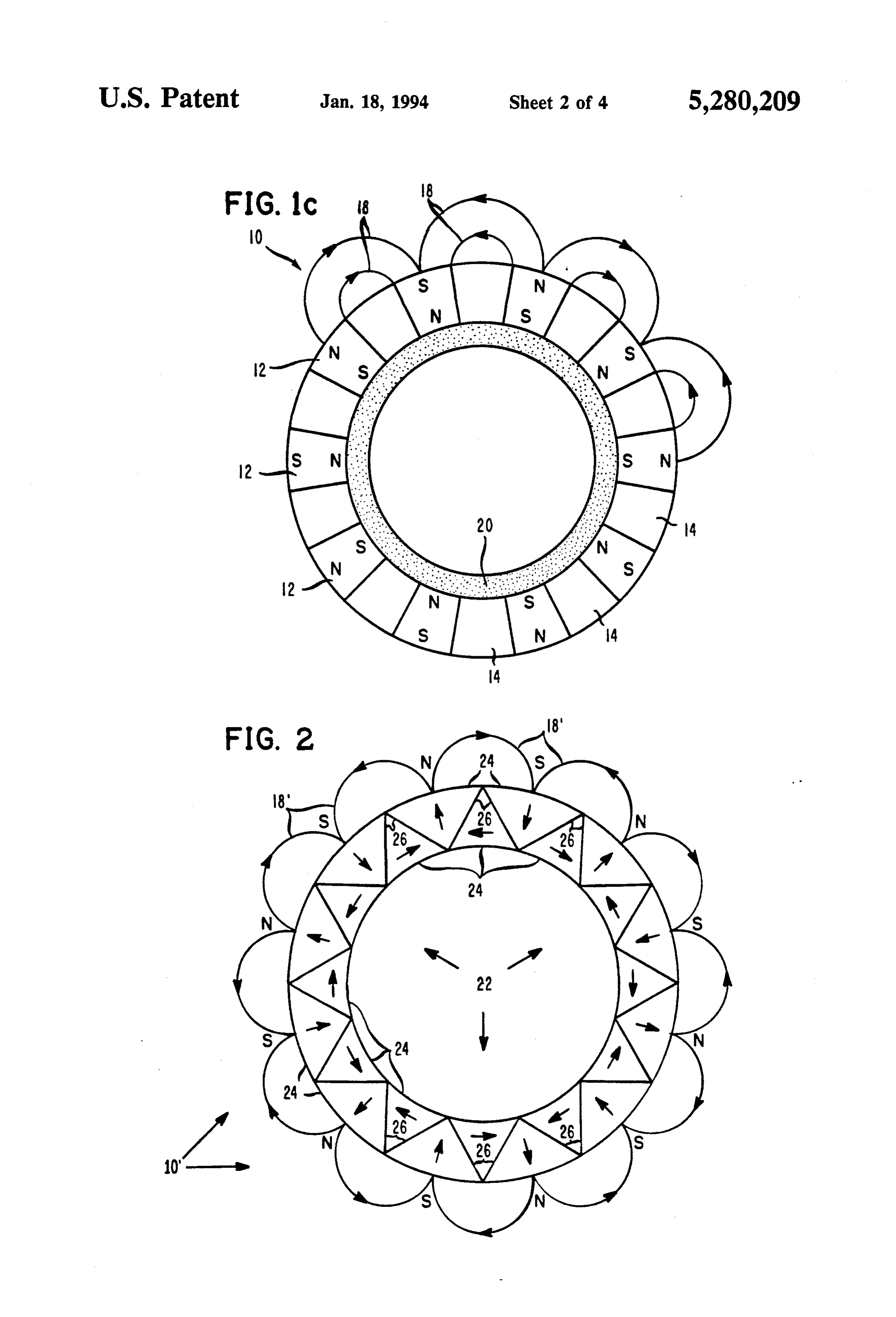
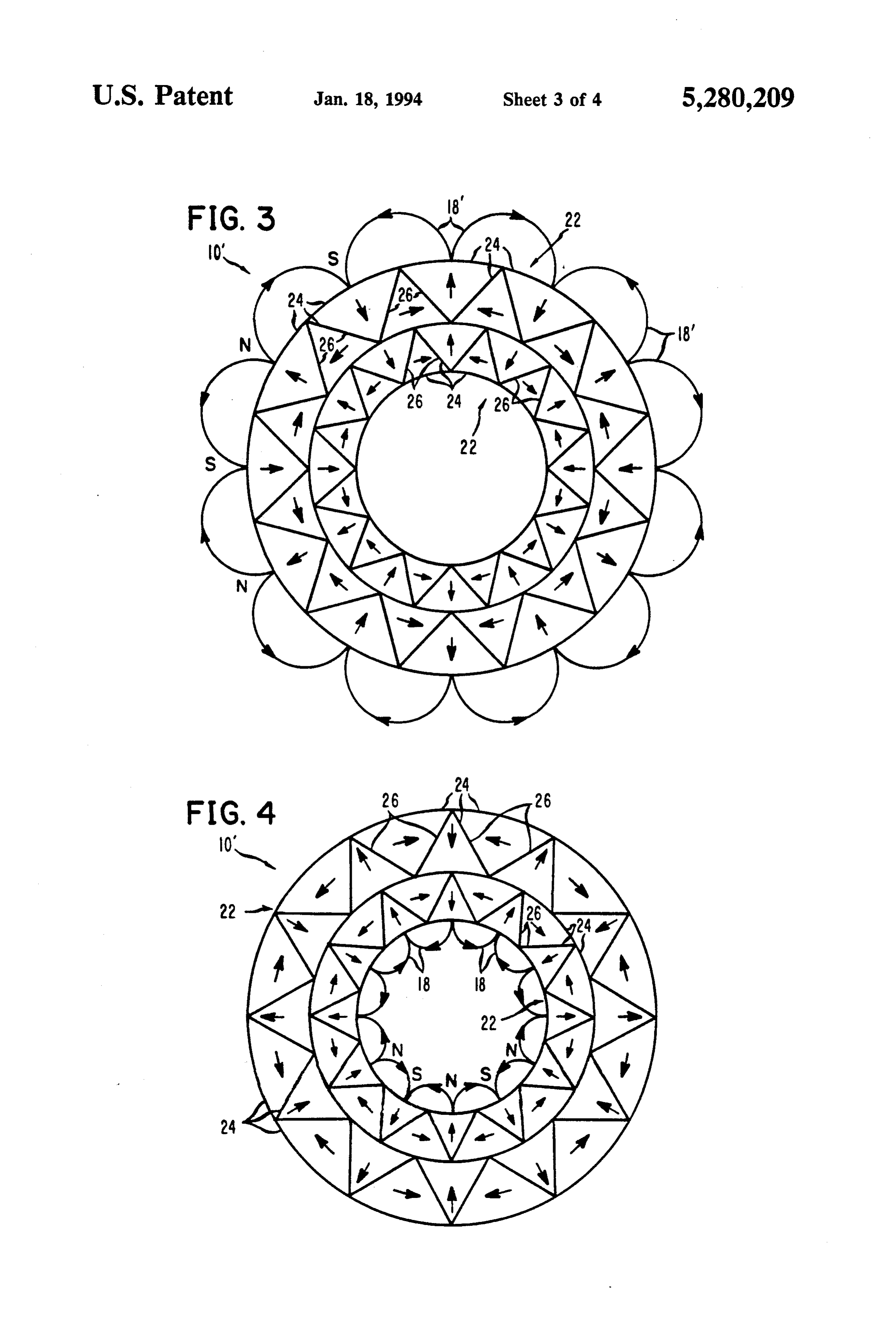
south poles can not be arranged on a cylindrical surface FIG. 2 is an end view of a permanent magnet struc within the electric machinery without encountering 25 ture in accordance with the invention and of the type flux leakage from corresponding north and south poles which incorporates on a rotor in electric machinery; remotely located from that cylindrical surface. Al FIG. 3 is an end view of another permanent magnet though shunting rings can be incorporated to preclude structure in accordance with the invention and of the such flux leakage in some electric machinery designs, type which incorporates on a rotor in electric machin they are very cumbersome to those designs. Pole pieces 30 ery;
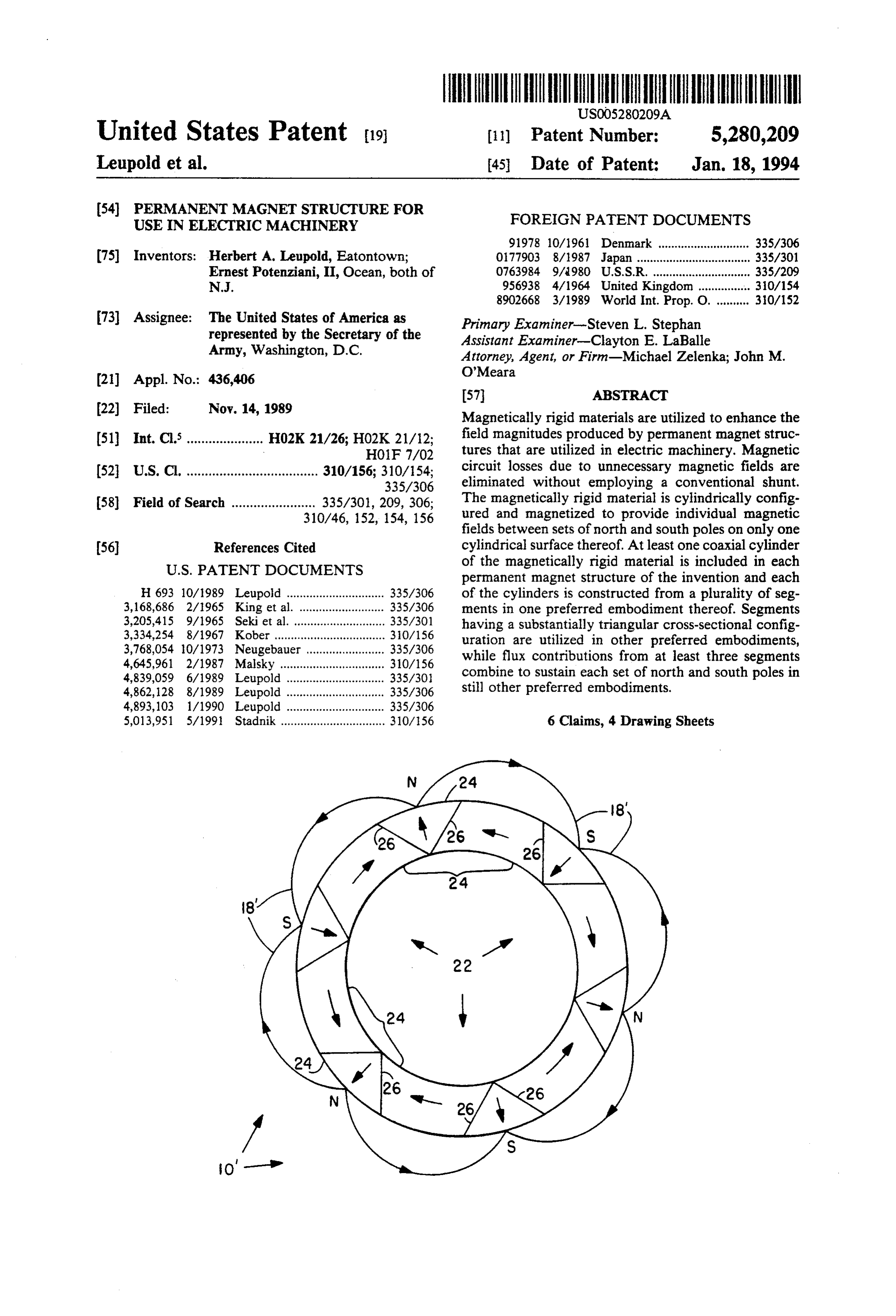
can be incorporated in those electric machinery designs FIG. 4 is an end view of still another permanent where shunting rings are not possible but they only magnet structure in accordance with the invention and reduce such flux leakage and therefore, do not com of the type which incorporates on a stator in electric pletely resolve the problem. Furthermore, as disclosed machinery, and by M. Marinescu, et al in their paper entitled NEW 35 FIG. 5 is an end view of a further permanent magnet RARE-EARTH PERMANENT MAGNET STRUC structure in accordance with the invention and of simi TURE FOR PRODUCING OPTIMAL MAGNETIC lar type to that of FIG. 2.
FIELDS IN MAGNETIC SEPARATION DE
VICES, COMPARISON WITH PREVIOUS SYS DESCRIPTION OF THE PREFERRED TEMS; pages 163-181 of the Proceedings of the Ninth EMBODIMENTS
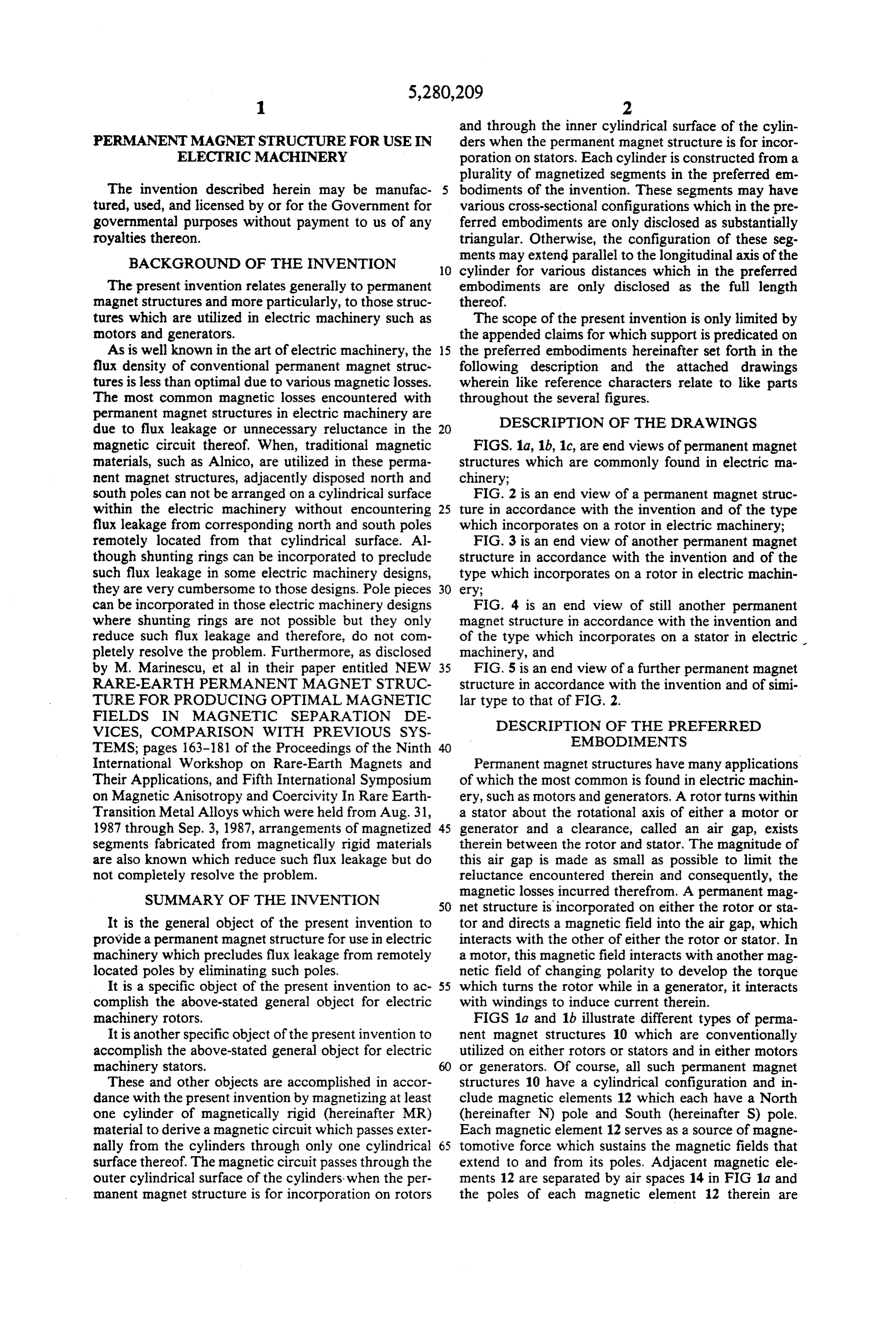
International Workshop on Rare-Earth Magnets and Permanent magnet structures have many applications Their Applications, and Fifth International Symposium of which the most common is found in electric machin on Magnetic Anisotropy and Coercivity In Rare Earth ery, such as motors and generators. A rotor turns within Transition Metal Alloys which were held from Aug. 31, a stator about the rotational axis of either a motor or 1987 through Sep. 3, 1987, arrangements of magnetized 45 generator and a clearance, called an air gap, exists segments fabricated from magnetically rigid materials therein between the rotor and stator. The magnitude of are also known which reduce such flux leakage but do this air gap is made as small as possible to limit the not completely resolve the problem. reluctance encountered therein and consequently, the SUMMARY OF THE INVENTION magnetic losses incurred therefrom. A permanent mag 50 net structure is incorporated on either the rotor or sta
It is the general object of the present invention to tor and directs a magnetic field into the air gap, which provide a permanent magnet structure for use in electric interacts with the other of either the rotor or stator. In machinery which precludes flux leakage from remotely a motor, this magnetic field interacts with another mag located poles by eliminating such poles. netic field of changing polarity to develop the torque It is a specific object of the present invention to ac 55 which turns the rotor while in a generator, it interacts complish the above-stated general object for electric with windings to induce current therein. machinery rotors. FIGS 1a and 1b illustrate different types of perma It is another specific object of the present invention to nent magnet structures 10 which are conventionally accomplish the above-stated general object for electric utilized on either rotors or stators and in either motors machinery stators. or generators. Of course, all such permanent magnet These and other objects are accomplished in accor structures 10 have a cylindrical configuration and in dance with the present invention by magnetizing at least clude magnetic elements 12 which each have a North one cylinder of magnetically rigid (hereinafter MR) (hereinafter N) pole and South (hereinafter S) pole. material to derive a magnetic circuit which passes exter Each magnetic element 12 serves as a source of magne nally from the cylinders through only one cylindrical 65 tomotive force which sustains the magnetic fields that surface thereof. The magnetic circuit passes through the extend to and from its poles. Adjacent magnetic ele outer cylindrical surface of the cylinders when the per ments 12 are separated by air spaces 14 in FIG 1a and manent magnet structure is for incorporation on rotors the poles of each magnetic element 12 therein are
Page 7
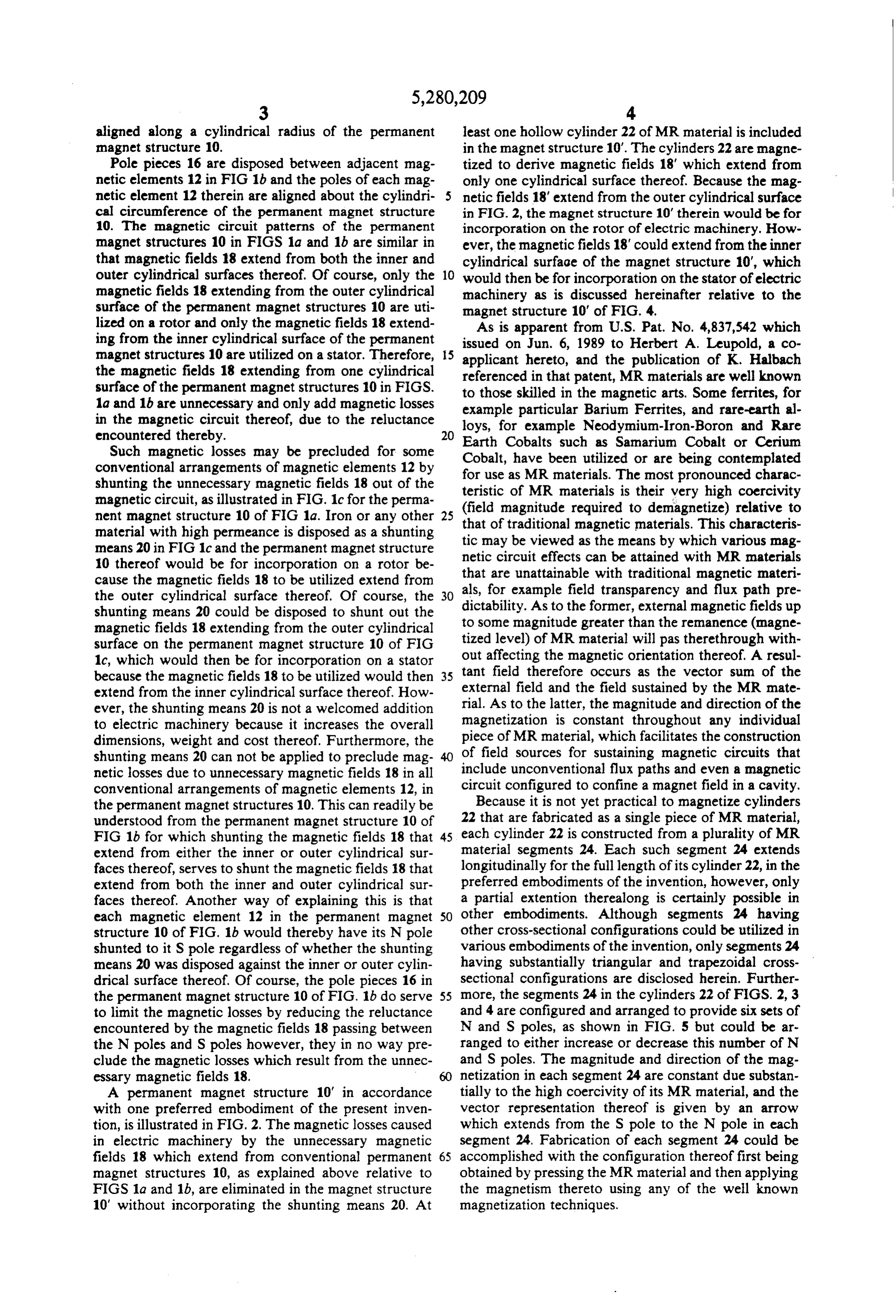
aligned along a cylindrical radius of the permanent least one hollow cylinder 22 of MR material is included magnet structure 10. in the magnet structure 10'. The cylinders 22 are magne Pole pieces 16 are disposed between adjacent mag tized to derive magnetic fields 18' which extend from netic elements 12 in FIG 1b and the poles of each mag only one cylindrical surface thereof. Because the mag netic element 12 therein are aligned about the cylindri netic fields 18' extend from the outer cylindrical surface cal circumference of the permanent magnet structure in FIG. 2, the magnet structure 10' therein would be for 10. The magnetic circuit patterns of the permanent incorporation on the rotor of electric machinery. How magnet structures 10 in FIGS 1a and 1b are similar in ever, the magnetic fields 18' could extend from the inner that magnetic fields 18 extend from both the inner and cylindrical surface of the magnet structure 10", which outer cylindrical surfaces thereof. Of course, only the 10 would then be for incorporation on the stator of electric magnetic fields 18 extending from the outer cylindrical machinery as is discussed hereinafter relative to the surface of the permanent magnet structures 10 are uti magnet structure 10' of FIG. 4.
lized on a rotor and only the magnetic fields 18 extend As is apparent from U.S. Pat. No. 4,837,542 which ing from the inner cylindrical surface of the permanent issued on Jun. 6, 1989 to Herbert A. Leupold, a co magnet structures 10 are utilized on a stator. Therefore, 15 the magnetic fields 18 extending from one cylindrical applicant referenced hereto, and the publication of K. Halbach in that patent, MR materials are well known surface of the permanent magnet structures 10 in FIGS. to those skilled in the magnetic arts. Some ferrites, for 1a and 1b are unnecessary and only add magnetic losses example particular Barium Ferrites, and rare-earth al in the magnetic circuit thereof, due to the reluctance loys, for example Neodymium-Iron-Boron and Rare encountered thereby. Earth Cobalts such as Sanarium Cobalt or Cerium Such magnetic losses may be precluded for some Cobalt, have been utilized or are being contemplated conventional arrangements of magnetic elements 12 by for use as MR materials. The most pronounced charac shunting the unnecessary magnetic fields 18 out of the teristic of MR materials is their very high coercivity magnetic circuit, as illustrated in FIG. 1c for the perma (field nent magnet structure 10 of FIG 1a. Iron or any other that ofmagnitude 25 required to demagnetize) relative to material with high permeance is disposed as a shunting tic may be viewed magnetic traditional as the materials. This characteris means by which various mag means 20 in FIG 1c and the permanent magnet structure netic circuit effects can be attained 10 thereof would be for incorporation on a rotor be that are unattainable with traditionalwith MR materials magnetic materi cause the magnetic fields 18 to be utilized extend from als, for example field transparency and flux path the outer cylindrical surface thereof. Of course, the 30 dictability. As to the former, external magnetic fieldspre up shunting means 20 could be disposed to shunt out the to some magnitude greater than the remanence (magne magnetic fields 18 extending from the outer cylindrical surface on the permanent magnet structure 10 of FIG tized level) of MR material will pas therethrough with 1c, which would then be for incorporation on a stator tant out affecting the magnetic orientation thereof. A resul because the magnetic fields 18 to be utilized would then 35 field therefore occurs as the vector sum of the extend from the inner cylindrical surface thereof. How external field and the field sustained by the MR mate ever, the shunting means 20 is not a welcomed addition rial. As to the latter, the magnitude and direction of the to electric machinery because it increases the overall magnetization is constant throughout any individual dimensions, weight and cost thereof. Furthermore, the piece of MR material, which facilitates the construction shunting means 20 can not be applied to preclude mag 40 of field sources for sustaining magnetic circuits that netic losses due to unnecessary magnetic fields 18 in all include unconventional flux paths and even a magnetic conventional arrangements of magnetic elements 12, in circuit configured to confine a magnet field in a cavity. the permanent magnet structures 10. This can readily be Because it is not yet practical to magnetize cylinders understood from the permanent magnet structure 10 of 22 that are fabricated as a single piece of MR material, FIG 1b for which shunting the magnetic fields 18 that 45 each cylinder 22 is constructed from a plurality of MR extend from either the inner or outer cylindrical sur material segments 24. Each such segment 24 extends faces thereof, serves to shunt the magnetic fields 18 that longitudinally for the full length of its cylinder 22, in the extend from both the inner and outer cylindrical sur preferred embodiments of the invention, however, only faces thereof. Another way of explaining this is that a partial extention therealong is certainly possible in each magnetic element 12 in the permanent magnet 50 other embodiments. Although segments 24 having structure 10 of FIG. 1b would thereby have its N pole other cross-sectional configurations could be utilized in shunted to it S pole regardless of whether the shunting various embodiments of the invention, only segments 24 means 20 was disposed against the inner or outer cylin having substantially triangular and trapezoidal cross drical surface thereof. Of course, the pole pieces 16 in sectional configurations are disclosed herein. Further the permanent magnet structure 10 of FIG. 1b do serve 55 more, the segments 24 in the cylinders 22 of FIGS. 2, 3 to limit the magnetic losses by reducing the reluctance and 4 are configured and arranged to provide six sets of encountered by the magnetic fields 18 passing between N and S poles, as shown in FIG. 5 but could be ar the N poles and Spoles however, they in no way pre ranged to either increase or decrease this number of N clude the magnetic losses which result from the unnec and Spoles. The magnitude and direction of the mag essary magnetic fields 18. netization in each segment 24 are constant due substan A permanent magnet structure 10' in accordance tially to the high coercivity of its MR material, and the with one preferred embodiment of the present inven vector representation thereof is given by an arrow tion, is illustrated in FIG. 2. The magnetic losses caused which extends from the S pole to the N pole in each in electric machinery by the unnecessary magnetic segment 24, Fabrication of each segment 24 could be fields 18 which extend from conventional permanent 65 accomplished with the configuration thereof first being magnet structures 10, as explained above relative to obtained by pressing the MR material and then applying FIGS 1a and 1b, are eliminated in the magnet structure the magnetism thereto using any of the well known 10' without incorporating the shunting means 20. At magnetization techniques.
Page 8
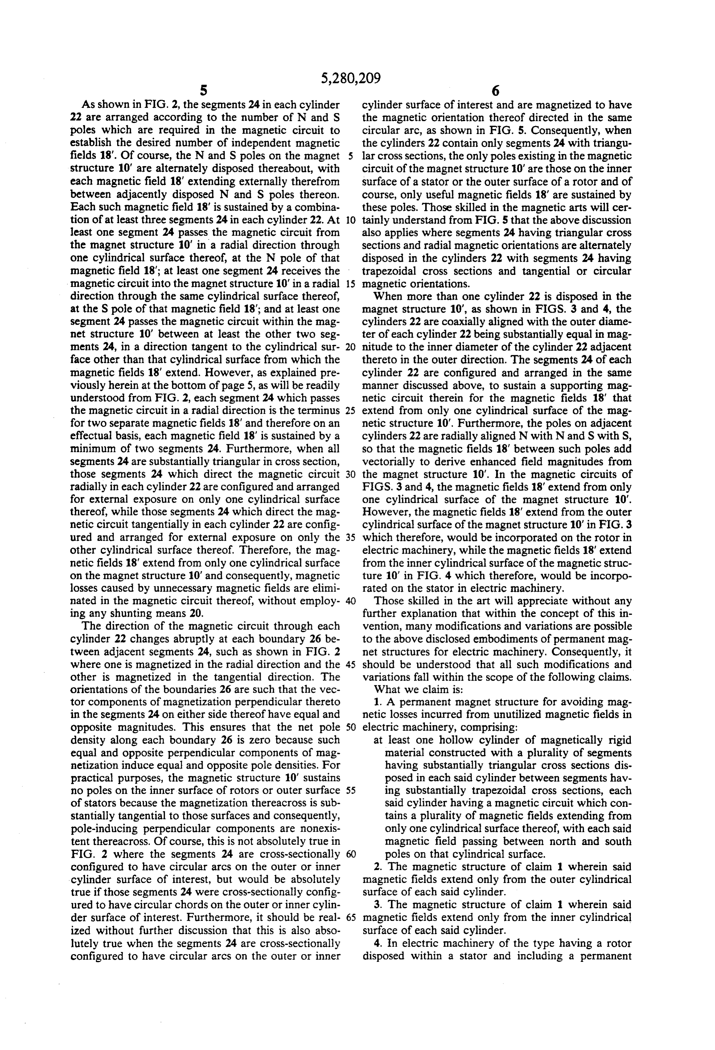
As shown in FIG. 2, the segments 24 in each cylinder cylinder surface of interest and are magnetized to have 22 are arranged according to the number of N and S the magnetic orientation thereof directed in the same poles which are required in the magnetic circuit to circular arc, as shown in FIG. 5. Consequently, when establish the desired number of independent magnetic the cylinders 22 contain only segments 24 with triangu fields 18'. Of course, the N and Spoles on the magnet lar cross sections, the only poles existing in the magnetic structure 10' are alternately disposed thereabout, with circuit of the magnet structure 10' are those on the inner each magnetic field 18' extending externally therefrom surface of a stator or the outer surface of a rotor and of between adjacently disposed N and S poles thereon. course, only useful magnetic fields 18' are sustained by Each such magnetic field 18' is sustained by a combina these poles. Those skilled in the magnetic arts will cer tion of at least three segments 24 in each cylinder 22. At 10 tainly understand from FIG. 5 that the above discussion least one segment 24 passes the magnetic circuit from also applies where segments 24 having triangular cross the magnet structure 10' in a radial direction through sections and radial magnetic orientations are alternately one cylindrical surface thereof, at the N pole of that disposed in the cylinders 22 with segments 24 having magnetic field 18"; at least one segment 24 receives the trapezoidal cross sections and tangential or circular magnetic circuit into the magnet structure 10' in a radial 15 magnetic orientations.
direction through the same cylindrical surface thereof, When more than one cylinder 22 is disposed in the at the Spole of that magnetic field 18"; and at least one magnet structure 10", as shown in FIGS. 3 and 4, the segment 24 passes the magnetic circuit within the mag cylinders 22 are coaxially aligned with the outer diame net structure 10" between at least the other two seg ter of each cylinder 22 being substantially equal in mag ments 24, in a direction tangent to the cylindrical sur 20 nitude to the inner diameter of the cylinder 22 adjacent face other than that cylindrical surface from which the thereto in the outer direction. The segments 24 of each magnetic fields 18' extend. However, as explained pre cylinder 22 are configured and arranged in the same viously herein at the bottom of page 5, as will be readily manner discussed above, to sustain a supporting mag understood from FIG. 2, each segment 24 which passes netic circuit therein for the magnetic fields 18' that the magnetic circuit in a radial direction is the terminus 25 extend from only one cylindrical surface of the mag for two separate magnetic fields 18' and therefore on an netic structure 10'. Furthermore, the poles on adjacent effectual basis, each magnetic field 18" is sustained by a cylinders 22 are radially aligned N with N and S with S, minimum of two segments 24. Furthermore, when all so that the magnetic fields 18' between such poles add segments 24 are substantially triangular in cross section, vectorially to derive enhanced field magnitudes from those segments 24 which direct the magnetic circuit 30 the magnet structure 10'. In the magnetic circuits of radially in each cylinder 22 are configured and arranged FIGS. 3 and 4, the magnetic fields 18' extend from only for external exposure on only one cylindrical surface one cylindrical surface of the magnet structure 10'. thereof, while those segments 24 which direct the mag However, the magnetic fields 18' extend from the outer netic circuit tangentially in each cylinder 22 are config cylindrical surface of the magnet structure 10' in FIG.3 ured and arranged for external exposure on only the 35 which therefore, would be incorporated on the rotor in other cylindrical surface thereof. Therefore, the mag electric machinery, while the magnetic fields 18' extend netic fields 18' extend from only one cylindrical surface from the inner cylindrical surface of the magnetic struc on the magnet structure 10' and consequently, magnetic ture 10' in FIG. 4 which therefore, would be incorpo losses caused by unnecessary magnetic fields are elimi rated on the stator in electric machinery. nated in the magnetic circuit thereof, without employ Those skilled in the art will appreciate without any ing any shunting means 20. further explanation that within the concept of this in The direction of the magnetic circuit through each vention, many modifications and variations are possible cylinder 22 changes abruptly at each boundary 26 be to the above disclosed embodiments of permanent mag tween adjacent segments 24, such as shown in FIG. 2 net structures for electric machinery. Consequently, it where one is magnetized in the radial direction and the 45 should be understood that all such modifications and other is magnetized in the tangential direction. The variations fall within the scope of the following claims. orientations of the boundaries 26 are such that the vec What we claim is:
tor components of magnetization perpendicular thereto 1. A permanent magnet structure for avoiding mag in the segments 24 on either side thereof have equal and netic losses incurred from unutilized magnetic fields in opposite magnitudes. This ensures that the net pole 50 electric machinery, comprising:
density along each boundary 26 is zero because such at least one hollow cylinder of magnetically rigid equal and opposite perpendicular components of mag material constructed with a plurality of segments netization induce equal and opposite pole densities. For having substantially triangular cross sections dis practical purposes, the magnetic structure 10' sustains posed in each said cylinder between segments hav no poles on the inner surface of rotors or outer surface 55 ing substantially trapezoidal cross sections, each of stators because the magnetization thereacross is sub said cylinder having a magnetic circuit which con stantially tangential to those surfaces and consequently, tains a plurality of magnetic fields extending from pole-inducing perpendicular components are nonexis only one cylindrical surface thereof, with each said tent thereacross. Of course, this is not absolutely true in magnetic field passing between north and south FIG. 2 where the segments 24 are cross-sectionally poles on that cylindrical surface. configured to have circular arcs on the outer or inner 2. The magnetic structure of claim 1 wherein said cylinder surface of interest, but would be absolutely magnetic fields extend only from the outer cylindrical true if those segments 24 were cross-sectionally config surface of each said cylinder.
ured to have circular chords on the outer or inner cylin 3. The magnetic structure of claim 1 wherein said der surface of interest. Furthermore, it should be real 65 magnetic fields extend only from the inner cylindrical ized without further discussion that this is also abso surface of each said cylinder. lutely true when the segments 24 are cross-sectionally 4. In electric machinery of the type having a rotor configured to have circular arcs on the outer or inner disposed within a stator and including a permanent
Page 9
magnetic structure for avoiding magnetic losses in magnetic field passing between north and south curred from unutilized magnetic fields, the improve poles on that cylindrical surface. ments comprising: 5. The electric machinery of claim 4 wherein said said permanent magnetic structure includes at least permanent magnet structure is incorporated on said one hollow cylinder of magnetically rigid material rotor, with said magnetic fields extending only from the constructed with a plurality of segments having outer cylindrical surface of each said cylinder. substantially triangular cross sections disposed in each said cylinder between segments having sub 6. The electric machinery of claim 4 wherein said stantially trapezoidal cross sections, each said cyl permanent magnet structure is incorporated on said inder having a magnetic circuit which contains a 10 stator, with said magnetic fields extending only from plurality of magnetic fields extending from only the inner cylindrical surface of eacht said cylinder. one cylindrical surface thereof, with each said
Provenance
- Collection
- Cited prior art
- Original PDF
- patentimages.storage.googleapis.com →
- Filed
- 1989-11-14
- Pages
- 9
- Method
- pdftotext (the PDF's own text layer) + pdftoppm 300dpi page scans
- Source
- Google Patents bibliographic record
- Granted
- 1994-01-18
- Inventors
- Herbert A. Leupold; II Ernest Potenziani; United States Department of the Army
- Transcribed from
- patentimages.storage.googleapis.com →