patent · US1979813
Rotor for magnetos
6 November 1934
Page 1
Drawing sheet — no readable text.
Page 2
Patented Nov. 6, 1934 1979,813
UNITED STATES PATENT OFFICE
ROTOR FOR MAGNETOS
Curt F. Reis, Beloit, Wis., assignor to Fairbanks,
Morse & Co., Chicago, Ill., a corporation of inois
Application October 27, 1933, Serial No. 695,386
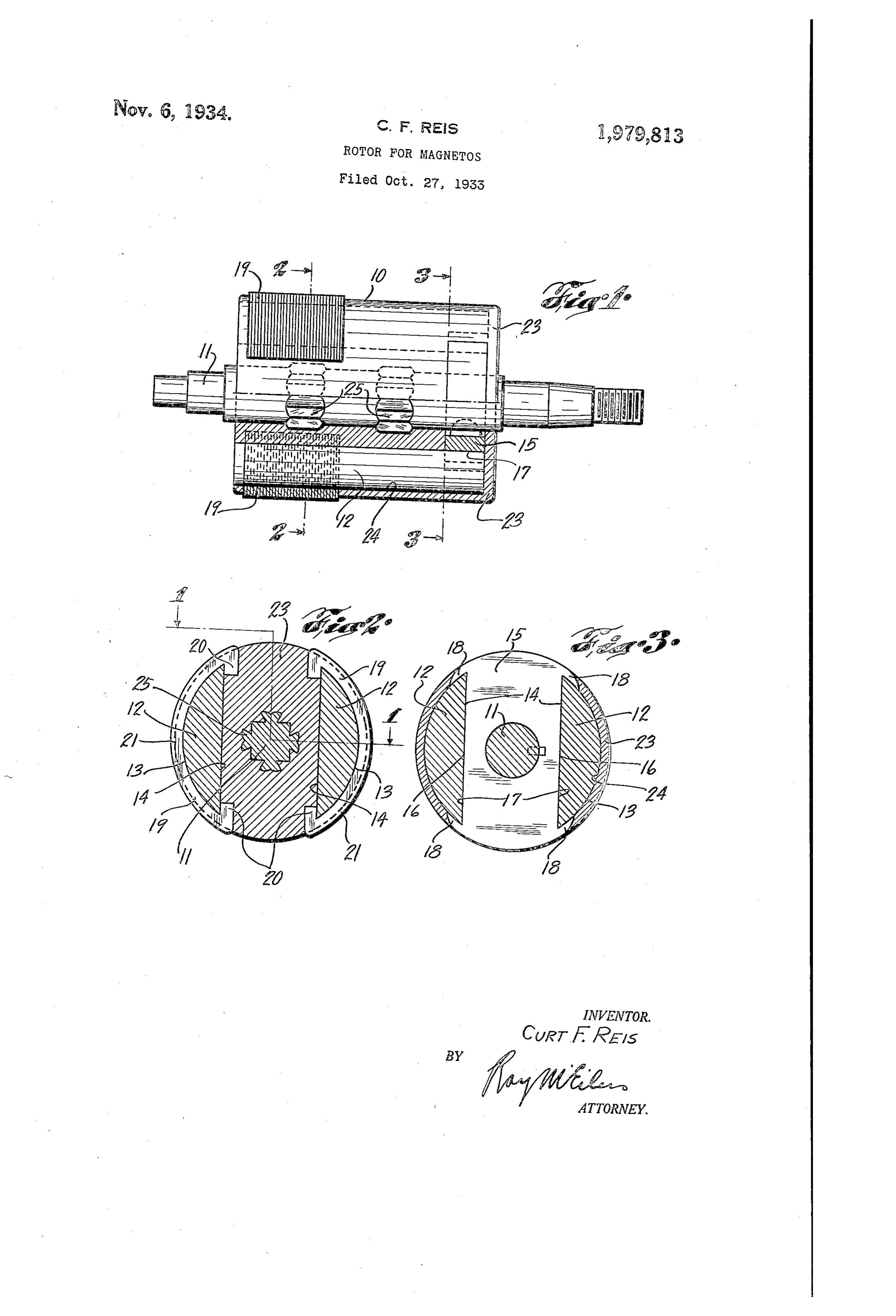
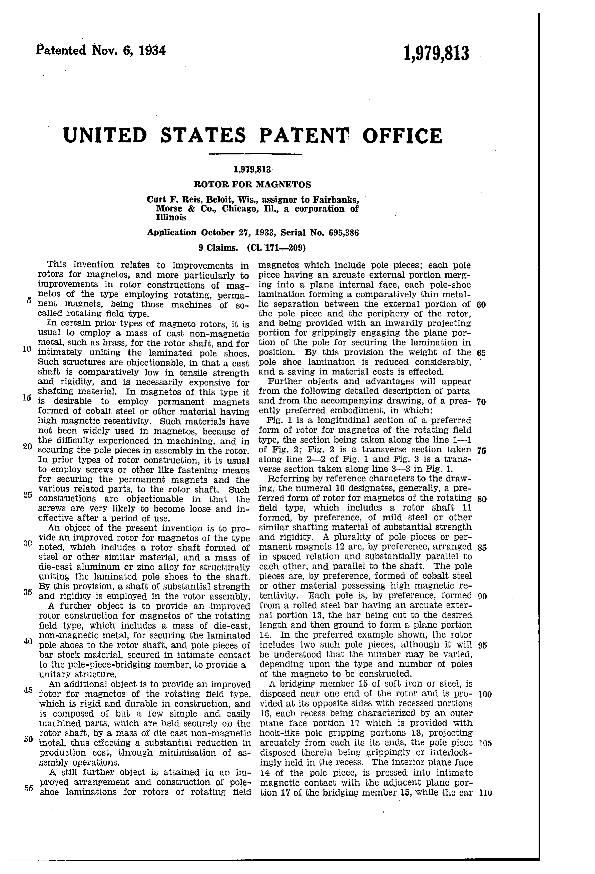
This invention relates to improvements in magnetOS which include pole pieces; each pole rotors for magnetos, and more particularly to piece having an arcuate external portion merg improvements in rotor constructions of mag ing into a plane internal face, each pole-shoe netos of the type employing rotating, perma lamination forming a comparatively thin metal 5 nent magnets, being those machines of so lic separation between the external portion of 60 called rotating field type. the pole piece and the periphery of the rotor, In certain prior types of magneto rotors, it is and being provided With an inwardly projecting usual to employ a mass of cast non-magnetic portion for grippingly engaging the plane por metal, such as brass, for the rotor shaft, and for tion of the pole for Securing the lamination in O intimately uniting the laminated pole shoes. position. By this provision the Weight of the 65 Such structures are objectionable, in that a cast pole shoe lamination is reduced considerably, shaft is comparatively low in tensile strength and a Saving in material costS is effected. and rigidity, and is necessarily expensive for Further objects and advantages will appear shafting material. In magnetos of this type it from the following detailed description of parts, is desirable to employ permanent magnets and from the accompanying dra Wing, of a pres 70 formed of cobalt steel or other material having ently preferred embodiment, in which: high magnetic retentivity. Such materials have Fig. 1 is a longitudinal section of a preferred not been Widely used in magnetos, because of form of rotor for magnetos of the rotating field the difficulty experienced in machining, and in type, the section being taken along the line 1 20 Securing the pole pieces in assembly in the rotor. of Fig. 2; Fig. 2 is a transverse Section taken 75 In prior types of rotor construction, it is usual along line 2-2. Of Fig. and Fig. 3 is a trans to employ Screws or other like fastening means verse Section taken along line 3-3 in Fig. 1. for Securing the permanent magnets and the Referring by reference characters to the dra W ing, the numeral 10 designates, generally, a pre 25 Various related parts, to the rotor shaft. Such constructions are objectionable in that the ferred form of rotor for magnetOS of the rotating 80 SCreWS are very likely to become loose and in field type, which includes a rotor Shaft 11 effective after a period of use. formed, by preference, of mild steel or other An object of the present invention is to pro similar shafting material of substantial strength
Wide an improved rotor for magnetos of the type and rigidity. A plurality of pole pieces or per noted, which includes a rotor shaft formed of manent magnets 2 are, by preference, arranged 85 Steel or other similar material, and a mass of in spaced relation and Substantially parallel to die-cast aluminum or zinc alloy for structurally each other, and parallel to the shaft. The pole uniting the laminated pole shoes to the shaft. pieces are, by preference, formed of cobalt steel By this provision, a shaft of substantial strength or other material pOSSessing high magnetic re 35 and rigidity is employed in the rotor assembly. tentivity. Each pole is, by preference, formed 90 A further object is to provide an improved from a rolled steel bar having an arcuate exter rotor construction for magnetos of the rotating nai portion 13, the bar being cut to the desired field type, which includes a mass of die-cast, length and then ground to form a plane portion
non-magnetic metal, for Securing the laminated 14. In the preferred example shown, the rotor pole shoes to the rotor shaft, and pole pieces of includes two such pole pieces, although it will 95 bar stock material, secured in intimate contact be understood that the alumber may be varied, to the pole-piece-bridging member, to provide a depending upon the type and number of poles unitary structure. of the magneto to be constructed. An additional object is to provide an improved A bridging member 15 of soft iron or steel, is 45 rotor for magnetos of the rotating field type, disposed near one end of the rotor and is pro OO which is rigid and durable in construction, and vided at its opposite sides With receSSed portions is composed of but a few simple and easily 16, each recess being characterized by an outer machined parts, which are held Securely on the piane face portion 17 which is provided with rotor Shaft, by a na SS of die cast non-nagnetic hook-like poie gripping portions 18, projecting 5 metal, thus effecting a substantial reduction in arcuately from each its its ends, the pole piece 05 production cost, through minimization of as disposed therein being grippingly or interiock Sembly operations. ingly held in the recess. The interior plane face A still further object is attained in an in 14 of the pole piece, is pressed into intimate proved arrangement and construction of pole magnetic contact with the adjacent plane por 55 shoe laminations for rotors of rotating field tion 7 of the bridging member 5, While the ear O
Page 3
or hook portions 18 grippingly engage the arcu seen that the mass of cast, non-magnetic metal ate external margins of the pole piece. The Secures the various parts of the rotor to the bridging member forms a flux path between the shaft, and thus eliminates practically all of the pair of poles of opposite polarity, to provide a former expensive and difficult machining opera 5 Structure which is, in effect, a permanent mag tions on the hard steel magnet metal, the only 80. net of U-shape or horseshoe type. operation advisable being that of grinding the It will be apparent that, as above noted, the plane face portions 14 of the pole pieces where bridging members and pole shoe laminations are they engage the member 15. This is simple and each provided With lateral recesses and hook-like inexpensive, as compared to the machining nec O terminal projections which are arranged to re essary with prior types of rotors. It will be ap 85 ceive and engage the pole pieces in mortised parent that the present, improved rotor is neat relation to prevent angular and diametral dis and compact in construction, and forms prac placement of the pole pieces with respect to the tically a rigid, balanced, rotating maSS. In the body of cast metal surrounding the pole pieces. preferred example, a decided advantage over 5 The bridging member may be Secured to the older prevailing types of magneto rotor con 90 rotor shaft 11 in any suitable manner, or may be structions, is attained in the particular forma Spaced therefrom to interrupt the magnetic path tion of the pole shoe laminations, which are through the shaft. Pole shoes 19 as provided, characterized by the narrow arcuate band of consist preferably of Stacks of Soft iron lamina metal for embracing the external arcuate mar 20 tions, each of a generally arcuate shape, the gin of the pole piece, and the inwardly extended 95 laminations constituting each shoe being Stacked pole gripping portions. By these provisions a in compression over an end portion of one of the substantial reduction in material cost and weight pole pieces 12. Each lamination is provided of the pole shoe laminations, is effected. with projecting pole piece gripping portions such It will, of course, be understood that the 25 as hook ends 20, for interlocking engagement present detailed description of parts and the ac 100 with the plane face portion 14 of the pole piece, companying drawings relates to only a single the portions 20 being connected by an unusually preferred executional embodiment of the inven narrow band 21. It Will be seen that the pole tion, and that substantial changes may be made shoe only partially encircles, but nevertheless in the described arrangement and construction 30 Snugly embraces, the corresponding pole piece, of parts without departing from the spirit and 05 by virtue of the shape and formation of the in full intended scope of the invention. Wardly extending portions 20 of the individual I claim as my invention:
laminations. 1. In a field structure for a magneto, spaced In assembling the rotor, the laminated pole pole pieces, a bridging member for the pole 35 shoes 19, rotor shaft 11, and bridging member pieces, pole shoes carried by the pole pieces, and 10 15, are suitably positioned in the relation of their provided with an internal pole receiving seat, final assembly, in a die-casting mold, with the adapted to engage the associated pole pieces in laminations Suitably kept in compressed rela mortised relation, and a body of metal disposed tion, and while the parts are so positioned, a centrally of the field structure, and constituting 40 mass of non-magnetic metal 23, Such as a Suit a Support for Said pole pieces, shoes and bridg 15 able aluminum or zinc alloy, is then poured into ing member.
the mold, intimately uniting in assembly with 2. In a rotor for a magneto of the rotating the shaft, the pole shoe laminations and bridg field type, a pair of spaced opposed permanent ing member. Before pouring, however, Suitable magnets, a body of cast non-magnetic metal 45 cores are provided in the mold so that upon between said magnets, a pole shoe for each of 120 casting there results a pair of longitudinal open said magnets, the shoes being of laminated con ings 24, each corresponding in Sectional shape struction and of general arcuate form, terminal to that of one of the pole pieces. Obviously, the projections on the laminations of said shoe pole pieces may be cast in place along with the adapted marginally to grip the pole shoes, and shoes, member 15 and shaft; I prefer, however, extended in Wardly of the rotor and into said 125 to core the openings or passages 24 and, after body of cast metal.
casting, to press the magnetS endwise into these 3. In a rotor for a rotating field type of mag passages, thus eliminating any thermal demag neto, a pair of pole pieces disposed in opposed netizing effects incident to casting the pole relation peripherally of the rotor, a body of 55 pieces in place. cast metal disposed between the pole pieces, and 130 My preference, according to the described pole shoes carried by the pole pieces, each of method and practice of casting the rotor body Said shoes being constituted by laminations each to the shaft, is to provide the shaft, Over Spaced of substantial 'C' shape and having a portion portions of its length, With externally angulate turned inwardly of the rotor and embedded in 60 keying portions 25, which, after casting, serve to said body of cast metal. interlock the shaft and the body of cast metal field 4. In a rotor for magnetos of the rotating 35 23, to preclude possibility of either endwise or type, Spaced pole pieces, a pole-piece-bridg angular, relative movement between the parts. ing member located diametrally of the rotor and - The portions 25 are preferably characterized having terminal projections adapted marginally 65 by acute angular recesses, so that it is impossi to engage the pole pieces so as to receive the
ble, due to any shrinkage effects, for the casting pole pieces therebetween, and coacting there metal to pull away from the shaft. with to prevent angular and diametral displace The rotor is now completed, ready for use in ment of the pole pieces with respect to the a magneto, and it will be apparent that, by the bridging member and other parts of the rotor. o above arrangement, that all screws or threaded 5. In a field structure for a magneto, spaced 145 fastening means for assembling the parts of the pole pieces, a bridging member having lateral rotor, are eliminated, a much simpler and more recesses adapted to receive and engage the pole secure assembly expedient being provided by the pieces in mortised relation, pole shoes carried die-casting metal. by the pole pieces, and a body of metal disposed 5 In the construction above described, it will be centrally of the field structure, and constituting 50
Page 4
a support for said pole pieces, shoes and bridg 8. In a rotor for r1agnetos of the rotating field ing member. type, a pair of pole pieces each of substantially 6. In a magneto rotor for a machine of the ro segmental cross section, a pole-piece-bridging tating field type, spaced pole pieces, a bridging member near one end of the pole pieces, a pole member having lateral recesses adapted to re shoe carried by each of the pole pieces near its 80 ceive the pole pieces, pole shoes carried by the end opposite the bridging member, the pole pole pieces, and a body of cast non-magnetic shoes and bridging member being characterized metal disposed centrally of the rotor structure by spaced paired hooklike terminal projections, and constituting a Support for said pole pieces, the paired projections adapted marginally to O shoes and bridging member, the bridging men grip the pole pieces, a shaft, and a body of die 3. ber and shoes each being provided With projec cast non-magnetic metal extending diametrally tions adapted marginally to engage the pole of the rotor and arranged to maintain the pole pieces, and coacting to position the bridging pieces, bridging member and pole shoes in as member, pole pieces and pole shoes against dis sembled relation to the shaft, and means formed 5 placement diametrally of the rotor. by the shaft for keyingly or interlockingly en 9. 7. In a rotor for a magneto of the rotating gaging the mass of die cast metal over a por field type, a pair of Spaced pole pieces, a pole tion of the length of the shaft internally of piece bridging member disposed near one end the rotor.
of the pole pieces, pole shoes disposed near the 9. In a rotor for an electric machine, of a 20 opposite ends of the pole pieces, Said bridging type embodying a mass of cast metal poured 95 member and pole shoe each being characterized about the rotor shaft, a plurality of metal-re by paired opposed acute angulate projections, ceiving seats, formed by the shaft, said seats the paired projections adapted to receive one being of a form to engage the poured metai of the pole pieces therebetween, a shaft, and in mortising relation.
25 means for Securing the pole pieces, bridging CURT F. R.E.S. O member and pole Shoes in assembled relation to the shaft.
Provenance
- Collection
- Cited prior art
- Original PDF
- patentimages.storage.googleapis.com →
- Filed
- 1933-10-27
- Pages
- 4
- Method
- pdftotext (the PDF's own text layer) + pdftoppm 300dpi page scans
- Source
- Google Patents bibliographic record
- Granted
- 1934-11-06
- Inventors
- Curt F Reis; Fairbanks Morse and Co
- Transcribed from
- patentimages.storage.googleapis.com →