patent · US2739253
Permanent magnet rotor
20 March 1956
Page 1
Drawing sheet — no readable text.
Page 2
United States Patent Office '- 2,739,253 Patented Mar. 20, 1956
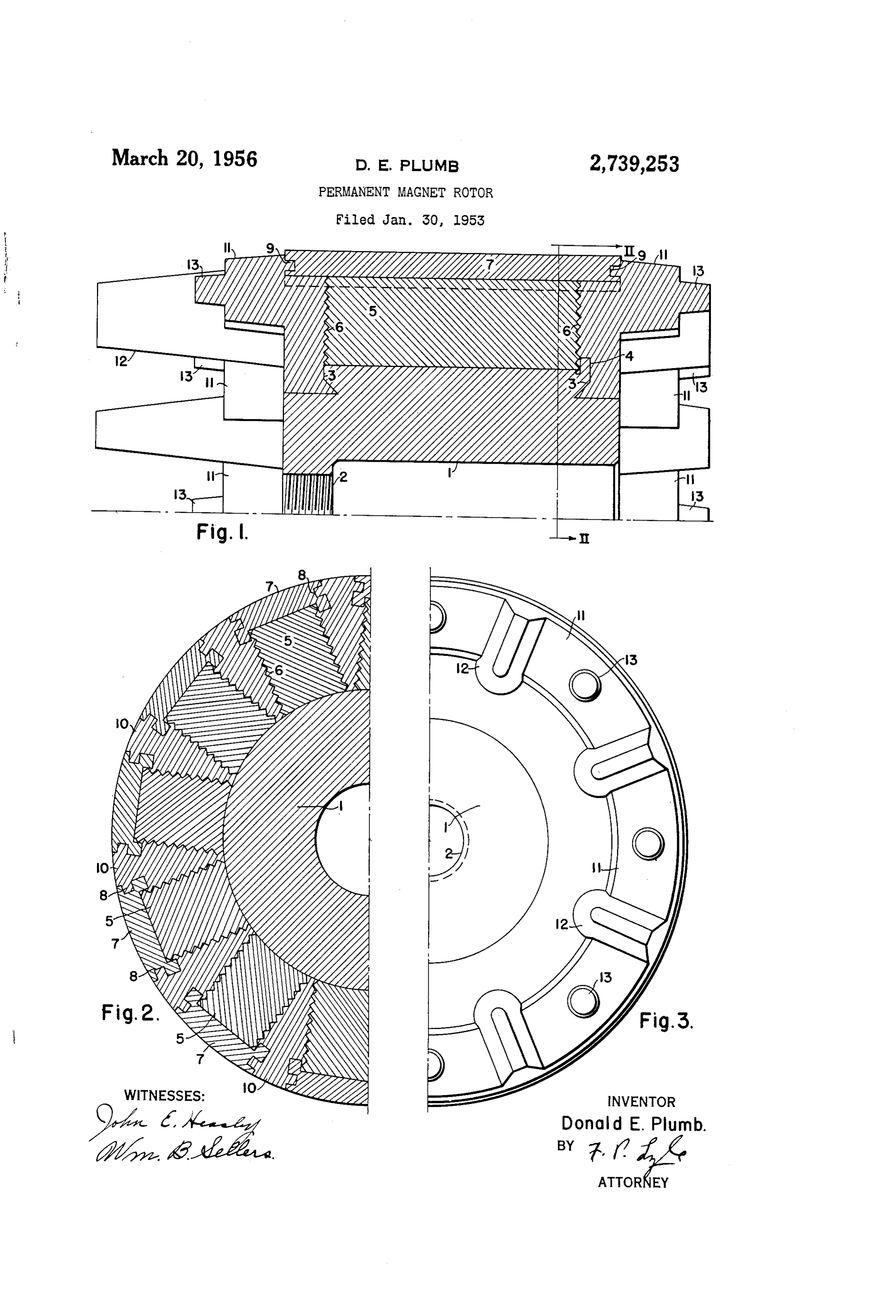
as including a quill shaft. 1, which may be made of steel or other suitable material, and which may be internally 2,739,253 threaded at one end, as indicated at 2, for mounting on a shaft. The quill 1 serves as a support member for
PERMANENT MAGNET ROTOR the poles of the rotor, and it will be evident that the Donald E. Plumb, Williamsville, N.Y., assignor to West poles might be supported directly on a solid shaft, if inghouse Electric Corporation, East Pittsburgh, Pa., a desired, or on a spider or support member of any other corporation of Pennsylvania suitable type. The quill shaft 1 has an undercut shoul Application January 30, 1953, Serial No. 334,290 der 3 at each end and a radial flange 4 may be provided 0. at one end to facilitate proper alignment of the mag 2 Claims. (Cl. 310-156) nets and quill during the die-casting operation. The poles of the rotor are formed by a plurality of permanent magnets, 5 disposed radially about the quill
The present invention relates to rotor members for 5 permanent shaft 1. The magnets 5 may be made of any suitable dynamo-electric machines, and more particularly, to a magnet alloy and are magnetized after assem bly permanent magnet rotor of simple and inexpensive con magnets 5 extend to provide magnetic poles of alternate polarity. The struction. longitudinally of the quill 1 and are Alternating current generators with permanent magnet both sides and on both ends.grooves provided with longitudinal
A pole or serrations 6 on shoe 7 is provided rotors are being used to an increasing extent as exciters 20 to supply excitation to the field winding of a main alter for each of the permanent magnets 5. The pole shoes 7 may be made of any suitable material having the re nating current generator, the output current of the al quired magnetic properties, and they extend longitudi ternating current exciter being rectified and supplied to nally and preferably extend beyond the permanent magnets the field of the main generator through a saturable reactor 5 at each end as shown in Fig. 1. The outer surfaces of or magnetic amplifier, which is used to control the field 25 the pole shoes 7 are arcuate and the inner surfaces con current. In such excitation systems, the frequency of form to the outer surfaces of the permanent magnets 5, the alternating current exciter is preferably relatively high, with the sides of the pole shoes preferably overlapping since the magnetic amplifier can be made smaller and the magnets, so that the pole shoes 7 fit on the magnets lighter in a high-frequency system, and this means that as shown in Fig. 2. Each of the pole shoes 7 has a longi the eXciter must have a rotor with a large number of 30 tudinal groove 8 in each side and a similar groove 9 poles, although its physical size is relatively small. In in each end.
the conventional construction of permanent magnet ro In assembling the rotor, the magnets 5 and pole shoes tors, the permanent magnets and pole shoes are individ 7 are placed in position on the quill 1 with the ends of ually secured to the shaft, or to a support member, by the magnets seating against the flange 4 to position them. means of bolts or screws, or other individual securing 35 means, and a suitable system of damper windings must The magnets and pole shoes are firmly clamped in place also be provided, one usual system consisting of a num in thedieproduction in a mold, which may be similar to the molds used of conventional die-cast squirrel-cage ber of bars equal to the number of poles and an end rotors, and which applies considerable radial clamping ring at each end of the rotor. Thus, in the conventional construction of high-frequency permanent magnet rotors, 40 aluminum or an aluminumisalloy, pressure. A cage structure then die-cast in place, using or any other conduc a large number of parts are required which are relatively tive material capable of being die-cast and having the Small and which are individually assembled and secured desired electrical resistivity. The cage structure consists to the Support and to each other, thus involving a com of longitudinal members 10 extending longitudinally be plicated structure and a difficult and expensive assembly tween the magnets 6, and substantially completely filling operation. 45
The principal object of the present invention is to pro the rings
Spaces between the magnets and pole shoes, and end 11 at each end which extend circumferentially of vide a permanent magnet rotor for dynamo-electric ma the rotor and are integrally joined to the longitudinal chines which is of simple and inexpensive construction. members 10. It will be seen that by die-casting the cage Another object of the invention is to provide a perma structure, the metal is caused to flow into the grooves 6, nent magnet rotor which can be easily and inexpensively 50 8 and 9 of the magnets and pole shoes, and into the un manufactured by means of standard tools and manufactur ing methods such as are used in the production of con and pole shoes are engaged by the3,cage dercut portions of the shoulders so that the magnets structure and rig ventional Squirrel-cage rotors. idly held in place. if desired, fan blades 12 and balanc A further object of the invention is to provide a per ing lugs 13 may be formed integral with the end rings in manent magnet rotor in which the magnets and pole the usual manner at one or both ends of the rotor. shoes are held in place by a cage structure which can be It will be evident that a construction has been provided die-cast in place and which rigidly holds the magnets for permanent magnet rotors which makes it possible to and pole shoes and also serves as a damper winding. assemble the rotor in a simple and relatively inexpensive Other objects and advantages of the invention will be manner by the use of apparent from the following detailed description, taken 60 ing methods which aretheused standard tools and manufactur for the production of con in connection with the accompanying drawing, in which: ventional Squirrel-cage rotors. The die-cast cage struc Figure 1 is a longitudinal sectional view of a rotor em ture rigidly holds the magnets and pole shoes in place bodying the invention; and a solid, rugged construction results with no parts Fig. 2 is a transverse sectional view approximately on which can loosen in service. Since no special tools or the line II-II of Fig. 1; and 65 manufacturing methods are required, the rotor can be Fig. 3 is an end view of the motor.
The invention is shown in the drawing embodied in a easily and inexpensively produced and the necessity of in permanent magnet rotor having twelve poles, for use in isdividually assembling a large number of separate parts a high-frequency alternating current exciter, although it since it not onlyThe eliminated. cage structure serves a dual purpose holds the parts of the assembly in place,
Will be apparent that the invention is applicable to rotors 70 but also serves as a damper winding, so that a very effec having any number of poles and intended for use in any tive, but simple and inexpensive structure is provided. type of dynamo-electric machine. The rotor is shown It will be understood that although a specific embodi
Page 3
ment of the invention has been shown and described for shoes on the magnets, said pole shoes having side portions the purpose of illustration, various modifications may be overlapping the magnets, the pole shoes and magnets each made within the scope of the invention, and the inven having grooves extending longitudinally thereof and hav tion is not restricted to the specific details shown, but in ing grooves extending transversely across their ends, and a cludes all equivalent embodiments and modifications. continuous metal cage structure having longitudinal por I claim as my invention: -- - - - tions substantially filling the spaces between the magnets 1. A rotor member for a dynamo-electric machine and engaging in the longitudinal grooves of the magnets comprising a rotatable support member, a plurality of and pole shoes and having circumferential end portions permanent magnets disposed radially about said Support at each end of the rotor integral with the longitudinal member, the support member having undercut shoulders O portions and engaging in the transverse grooves of the adjacent each end of the magnets, solid imperforate pole magnets and pole shoes and in said shoulders, the cage shoes on the magnets, said pole shoes having side por structure rigidly retaining the magnets and pole shoes tions overlapping the magnets, the pole shoes and mag in place and forming a short-circuited winding. nets each having grooves extending longitudinally thereof and having grooves extending transversely across their References Cited in the file of this patent ends, and a continuous mass of metal filling the longitudi UNITED STATES PATENTS nal spaces between the magnets and extending circumfer 2,475,776 Brainard -------------- July 12, 1949 entially at both ends of the magnets to form a short-cir 2,488,437 Schaefer -------------- Nov. 15, 1949 cuited winding, said metal engaging in said grooves and 2,488,729 Kooyman -------------- Nov. 22, 1949 said shoulders to hold the magnets and pole shoes rigidly 2,626,367 . Beymer ---------------- Jan. 20, 1953 in place.
2. A rotor member for a dynamo-electric machine com FOREIGN PATENTS prising a rotatable support member, a plurality of per 419,119 Italy ----------------- Mar. 13, 1947 manent magnets disposed radially about said support 604,762 Great Britain ------------ July 9, 1948 member, the support member having undercut shoulders 25 adjacent each end of the magnets, solid imperforate pole
Provenance
- Collection
- Cited prior art
- Original PDF
- patentimages.storage.googleapis.com →
- Filed
- 1953-01-30
- Pages
- 3
- Method
- pdftotext (the PDF's own text layer) + pdftoppm 300dpi page scans
- Source
- Google Patents bibliographic record
- Granted
- 1956-03-20
- Inventors
- Donald E Plumb; Westinghouse Electric Corp
- Transcribed from
- patentimages.storage.googleapis.com →