patent · US3841643
Seal for bearings and similar rotating members
15 October 1974
Page 1 — bibliographic record
United States Patent (19) 11 3,841,643 McLean (45) Oct. 15, 1974 54 SEAL FOR BEARINGS AND SEMILAR 394,606 6, 1933 Great Britain........................ 277/57 ROTATENG MEMBERS 15,768 Of 1944 Sweden.................'............... 277.157 76 Inventor: Neil J. McLean, Rt. 3, Box 467B,
Plymouth, Ind. 46563 Primary Examiner-Louis R. Prince 22 Filed: Jan. 21, 1972 Assistant Examiner-Robert I. Smith Attorney, Agent, or Firm-Oltsch & Knoblock
52 U.S.C. .................................................. 277/57 57 ABSTRACT
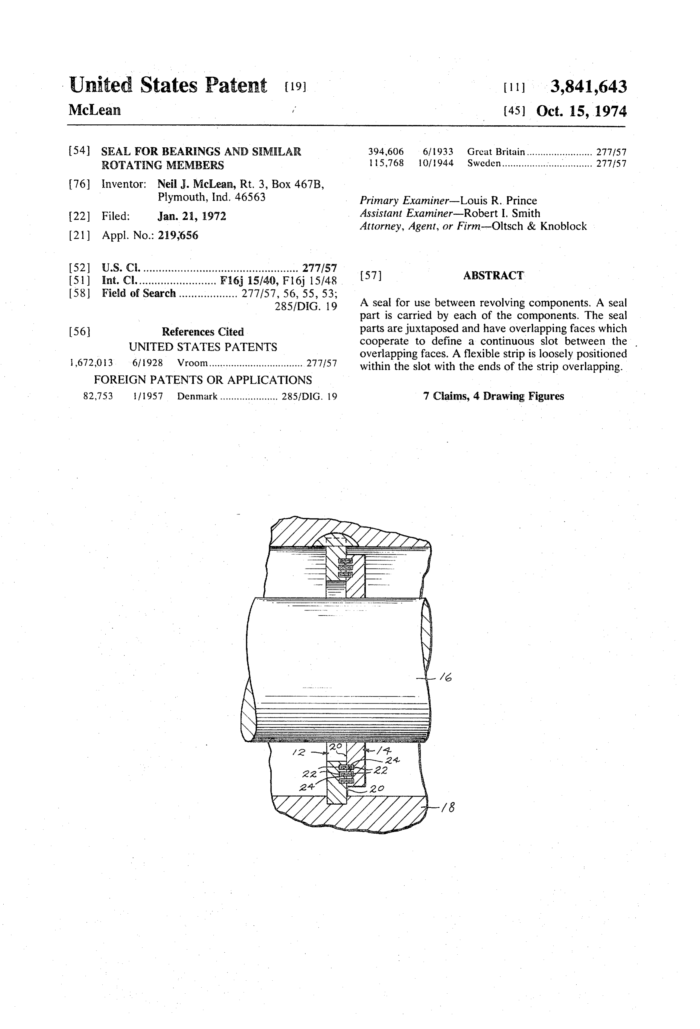
285/DIG. 19 A seal for use between revolving components. A seal part is carried by each of the components. The seal 56 References Cited parts are juxtaposed and have overlapping faces which UNITED STATES PATENTS cooperate to define a continuous slot between the overlapping faces. A flexible strip is loosely positioned 1672,013 6, 1928 Vroom.................................. 277.157 within the slot with the ends of the strip overlapping.
FOREIGN PATENTS OR APPLICATIONS
82,753 fl957 Denmark ..................... 285/DIG. 19 7 Cains, 4 Drawing Figures
Page 2
Drawing sheet — no readable text.
Page 3
SEAL FOR BEARINGS AND SIMELAR ROTATING best explain the invention and its application and prac MEMBERS tical use to thereby enable others skilled in the art to SUMMARY OF THE INVENTION best utilize the invention.
This invention relates to a seal for use between re
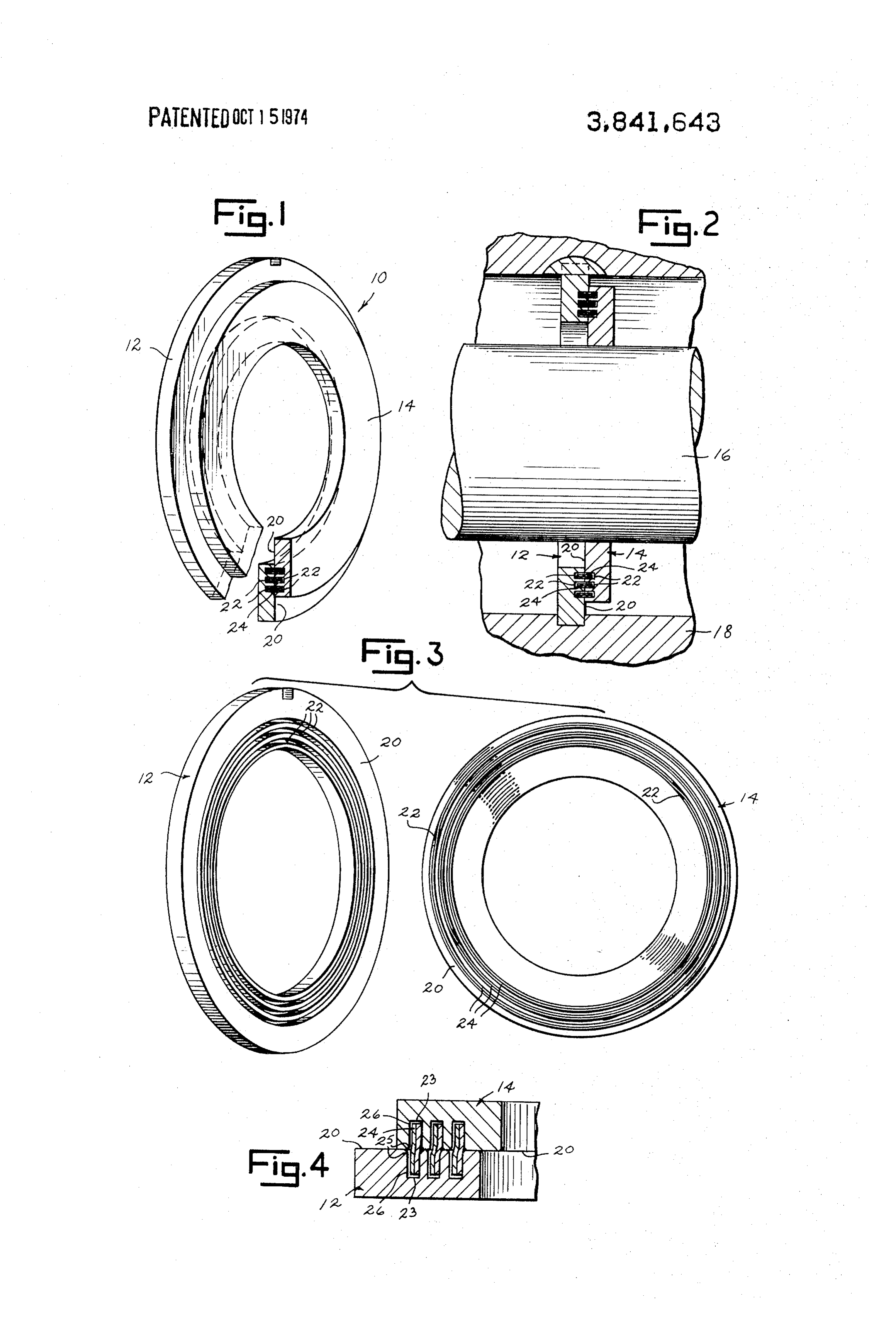
The illustrated seal of this invention is designated by the reference numeral 10 and includes ring parts 12 volving parts and will have particular application to and 14 which encircle shaft 16. Ring part 14 of seal 10 bearing seals. is secured to shaft 16, preferably by a press fit, for rota The seal of this invention includes first and second tion with the shaft. Ring part 12 encircles shaft 16 with seal parts. The first seal part is secured to one compo clearance and is secured to housing 18 in a suitable nent and the second seal part is secured to the other manner, such as by the groove and key arrangement il component of a pair of components which experience lustrated in FIG. 2. Ring parts 12 and 14 overlap at relative revolving movement. The seal parts have con confronting faces 20. Each face 20 of ring parts 12 and fronting continuous faces with at least one of the faces 14 have at least one and preferably a plurality of con being shiftable over the other face during revolving tinuous grooves 22 formed therein. Grooves 20 are cir movement of the components. The face of the first seal 15 cular in configuration and coaxial with the axis of revo part has a continuous groove formed therein. The face lution of shaft 16. Each groove 22 in ring part 12 is op of the second seal part includes means which cooperate positely positioned from a similar groove 22 in ring part with the groove in the first seal part to form a continu 14 and defines with that groove a continuous annular ous slot between the faces of the seal parts. An elon slot.
gated flexible strip is fitted loosely within and extends 20 An elongated strip 24 is fitted within each slot entirely around the slot between the seal part faces. formed by opposed grooves 22. Strip 24 extends en The strip has overlapping ends and a width which is suf tirely around the slot and has its end portions overlap ficient to overlap portions of both seal parts in all oper ping. The amount of overlap of the end portions of ative positions of the components. each strip 24 can vary depending upon the material The seal of this invention can be economically manu 25 from which the strip and ring parts are constructed and factured and will provide a suitable barrier in both posi the particular application for which the seal is used. tive pressure and vacuum environments. While this seal Each strip 24 overlaps a portion of both ring parts 12 will have principal application in the bearing seal art and 14 and has a width which does not exceed the for rotatable shafts, it is to be understood that the seal depth of the slot as measured between the bases 23 of can be utilized between various rotating objects, such 30 the opposed grooves 22. Each strip 24 fits loosely as an endless conveyor belt and its housing.
Accordingly, it is an object of this invention to pro within its slot so as to allow for its diametrical expan sion or contraction within the slot depending upon vide a seal for use between components experiencing whether the seal is subjected to a positive or negative relative rotating movement. pressure gradient. To facilitate rotative movement be Another object of this invention is to provide a bear 35 tween seal parts 12 and 14 and the expansion and con ing seal having one part connected to a shaft and an traction of the strip within the seal parts, it is preferable other part connected to the housing for the shaft with that each strip be constructed of a low friction material, at least one flexible strip fitted within a continuous slot such as Teflon.
encircling the shaft and formed between confronting 40 In FIG. 4, opposed grooves 22 of seal ring parts 12 faces of the seal parts. and 4 are shown in slight misalignment. The intersec Another object of this invention is to provide a seal tion 25 of each groove side wall 26 with the face 20 of for rotating members which is of economical construc the groove-defining ring part is rounded so as to facili tion and which would have application in either vac tate flexure of strip 24, as illustrated, when positioned uum or positive pressure environments, within the groove with the ring parts in misalignment. Other objects of this invention will become apparent 45 In this manner seal 10 can be constructed to accommo upon a reading of the invention's description. date misalignment between the revolving parts, such as BRIEF DESCRIPTION OF THE DRAWING shaft i6 and its housing 18 to which it is secured, Rotation of shaft 16 within housing 18 causes ring
A preferred embodiment of this invention has been 50 part 4 to revolve relative to ring part 12. Strips 24, in chosen for purposes of illustration and description conjunction with the ring parts, form a labyrinth which wherein: prevents the passage of material, such as air, liquid, or FIG. 1 is a perspective view of the embodiment hav fine particulate matter, through the seal. ing portions thereof broken away for purposes of illus It is to be understood that the invention is not to be tration. limited to the details herein given, but may be modified FIG. 2 is a sectional view of the seal of FIG. shown 55 within the scope of the appended claims. connected between a rotating shaft and its housing. What I claim is:
FIG. 3 is a perspective view showing the components 1. A seal for use between components experiencing of the seal of FIG. 1 in exploded form. relative revolving movement comprising a first seal part FIG. 4 is an enlarged fragmentary detailed cross sec adapted to be secured to one of the components and a tional view of the seal of FIG. 1 showing the component 60 second seal part adapted to be secured to the other of parts thereof in slight misalignment. the components, said seal parts having confronting DESCRIPTION OF THE PREFERRED continuous faces with at least one face being shiftable EMBODIMENT over the other face during revolving movement of said components, the face of the first seal part having a con
The preferred embodiment illustrated is not intended 65 tinuous groove formed therein, the face of said second to be exhaustive or to limit the invention to the precise seal part including means cooperating with said groove form disclosed. It is chosen and described in order to to form a continuous slot between said faces, an elon
Page 4
gated flexible strip positioned loosely between each of 3. The seal of claim 2 wherein said cooperating said seal parts and fitting within and extending entirely means of the other said face is a continuous groove po around said slot, said strip having overlapping ends and sitioned oppositely of the groove in the one said face a width sufficient to overlap portions of said first and and defining said slot.
second seal parts in all operative positions of the seal. 4. The seal of claim 3 wherein each groove includes 2. A seal for use between a housing and a shaft ex side walls and a base, the width of said strip exceeding the depth of each groove as measured from the face of tending through said housing, wherein one of said shaft each ring to the base of the groove therein but being and housing experiences rotative movement relative to less than the distance between the bases of said the other of the shaft and housing, comprising a pair of 10 grooves.
rings each adapted to encircle said shaft, one ring adapted for securement to the shaft and the other ring of5.each The seal of claim 4 wherein the junction of the face ring and each side wall of the groove therein is adapted for securement to the housing, said rings over of a rounded configuration to facilitate flexure of the lapping and having confronting continuous faces, one strip upon misalignment of said grooves. said face having a continuous groove formed therein, 15 the other said face including means cooperating with rality of oppositely positioned said 6. The seal of claim 3 wherein faces have a plu continuous grooves said groove to form a continuous slot between said faces and encircling said shaft, an elongated flexible formed therein defining at least one other continuous strip fitting loosely between each of said rings within slot, a said flexible strip fitting loosely within each slot. and extending entirely around said slot, said strip hav ing overlapping ends and a width sufficient to overlap 7. The seal of claim 6 wherein said slots are circular a portion of each ring in all operative positions of said and coaxial with the axis of rotation of said one shaft seal upon rotative movement of said one shaft or hous or housing.
Ing. k k k k k
Provenance
- Collection
- Cited prior art
- Original PDF
- patentimages.storage.googleapis.com →
- Filed
- 1972-01-21
- Pages
- 4
- Method
- pdftotext (the PDF's own text layer) + pdftoppm 300dpi page scans
- Source
- Google Patents bibliographic record
- Granted
- 1974-10-15
- Inventors
- N Mclean
- Transcribed from
- patentimages.storage.googleapis.com →