patent · US4292532
Two-stage electric generator system
29 September 1981
Page 1 — bibliographic record
United States Patent (19) 11 4,292,532 Leroux 45 Sep. 29, 1981 (54) TWO-STAGE ELECTRIC GENERATOR Attorney, Agent, or Firm-Cushman, Darby & Cushman
SYSTEM
(75) Inventor: Adrien Leroux, Sherbrooke, Canada The system described herein is particularly adapted to 73 Assignee: h.o.p. Consulab Inc., Quebec, convert mechanical energy from a wind or hydraulic Canada driven turbine into electric energy and comprises: an (21) Appl. No.: 136,707 exciter generator and a main generator in a housing traversed by a rotatable shaft; the exciter generator 22 Filed: Apr. 2, 1980 consists of permanent magnet mounted to the housing (30) Foreign Application Priority Data envelope and of a rotor mounted to the shaft and having a one-phase winding, the rotor being made of non-mag
Mar. 14, 1980 CA) Canada ................................... 347792 netic material to eliminate cogging and static torque 51 Int. Cl. ........................ H02P 9/04; HO2K 19/12 associated with permanent magnet excitation; the main 52 U.S. Cl. ........................................ 290/6; 310/165; generator consists of a three-phase stator winding on a 310/190 magnetic core mounted to the housing envelope and of 58 Field of Search ................. 290/6; 310/165, 68 D, a pole-type rotor mounted to the shaft, the rotor having 310/152, 154, 190, 191, 68 R, 262, 266 a winding wound on a magnetic core; a rectifying
bridge is rotatably mounted to the shaft and is con nected to the one-phase winding of the rotor of the
ator rotor so that the rotation of the shaft as a result of 3,356,877 12/1967 Burr .................................... 310/154 mechanical energy generates a three-phase electric en
ergy output from the stator winding.
Primary Examiner-J. V. Truhe
Assistant Examiner-Donald L. Rebsch 4 Claims, 2 Drawing Figures
trihin tirh in
Sceaezar % Aaen area A. Aaaaaaa electric enri (utput
Page 2
Drawing sheet — no readable text.
Page 3
Drawing sheet — no readable text.
Page 4
tailed description given hereinafter; it should be under
Two-STAGE ELECTRIC GENERATOR SYSTEM stood, however, that the detailed description while This invention relates to an electric generator indicating preferred embodiments of the invention is matched to turbine power. given by way of illustration only since various changes Wind energy and hydraulic energy, when converted and modifications within the spirit and scope of the to mechanical energy with a propeller-type turbine, invention will become apparent to those skilled in the yield a normalized relation between power and speed in art.
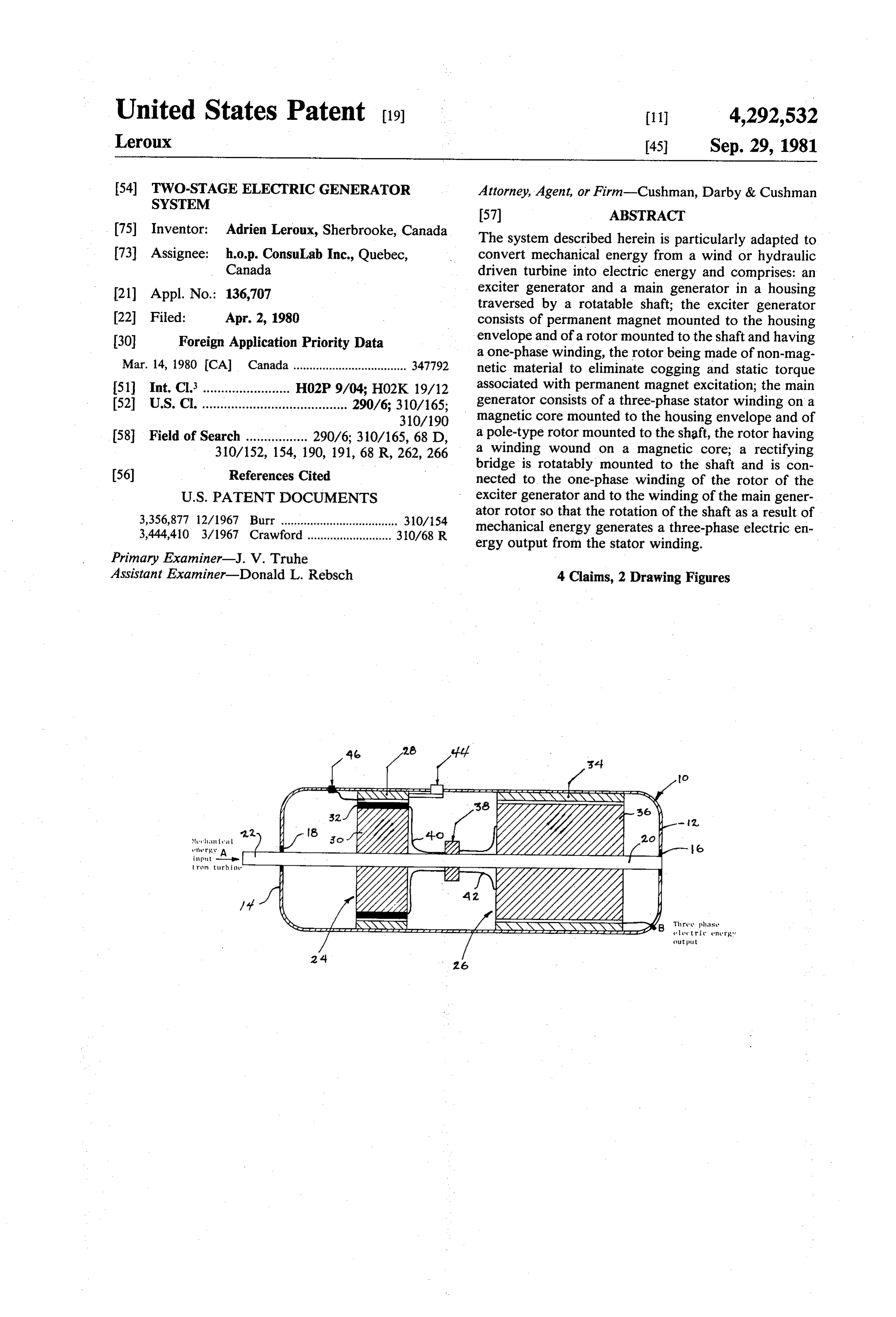
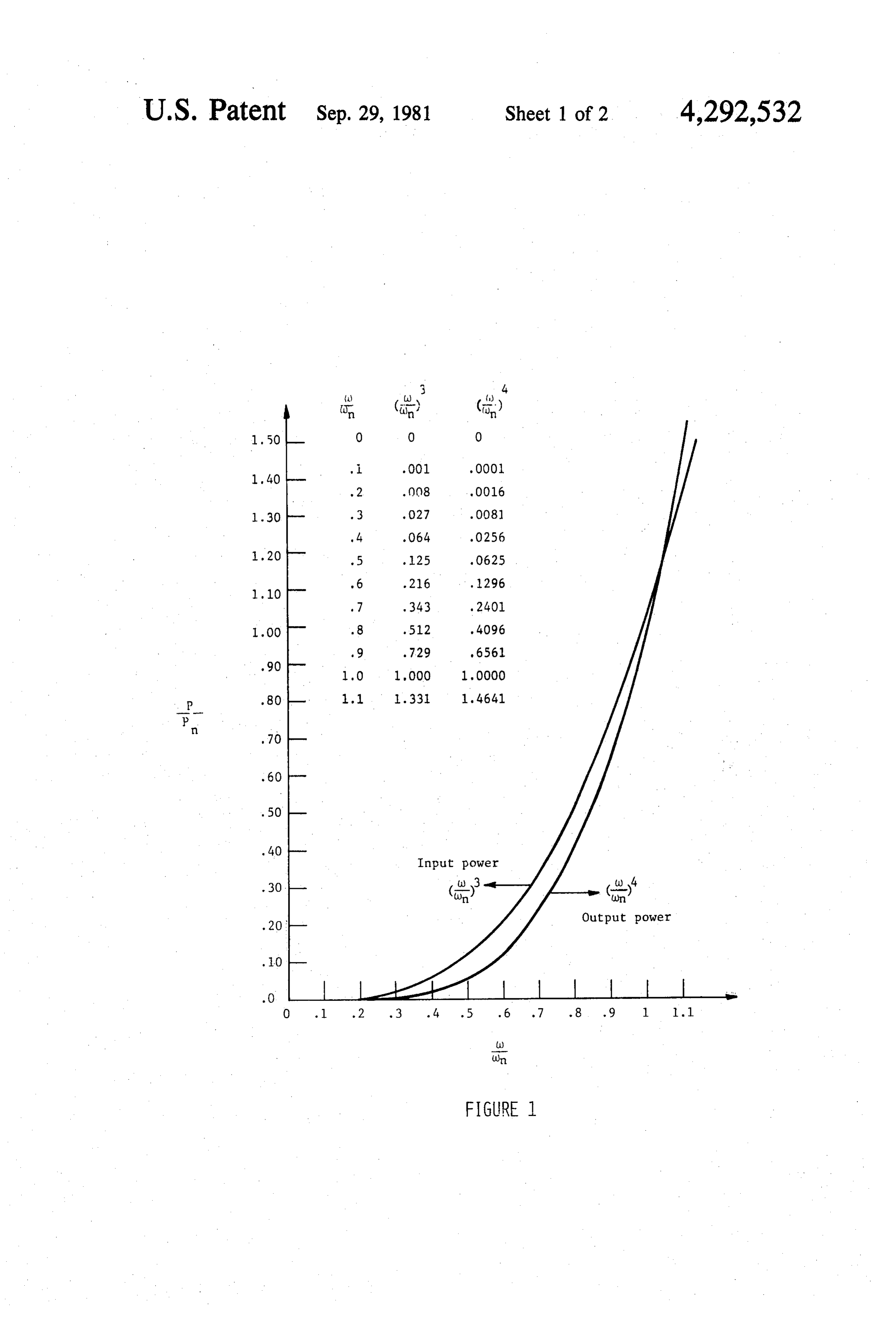
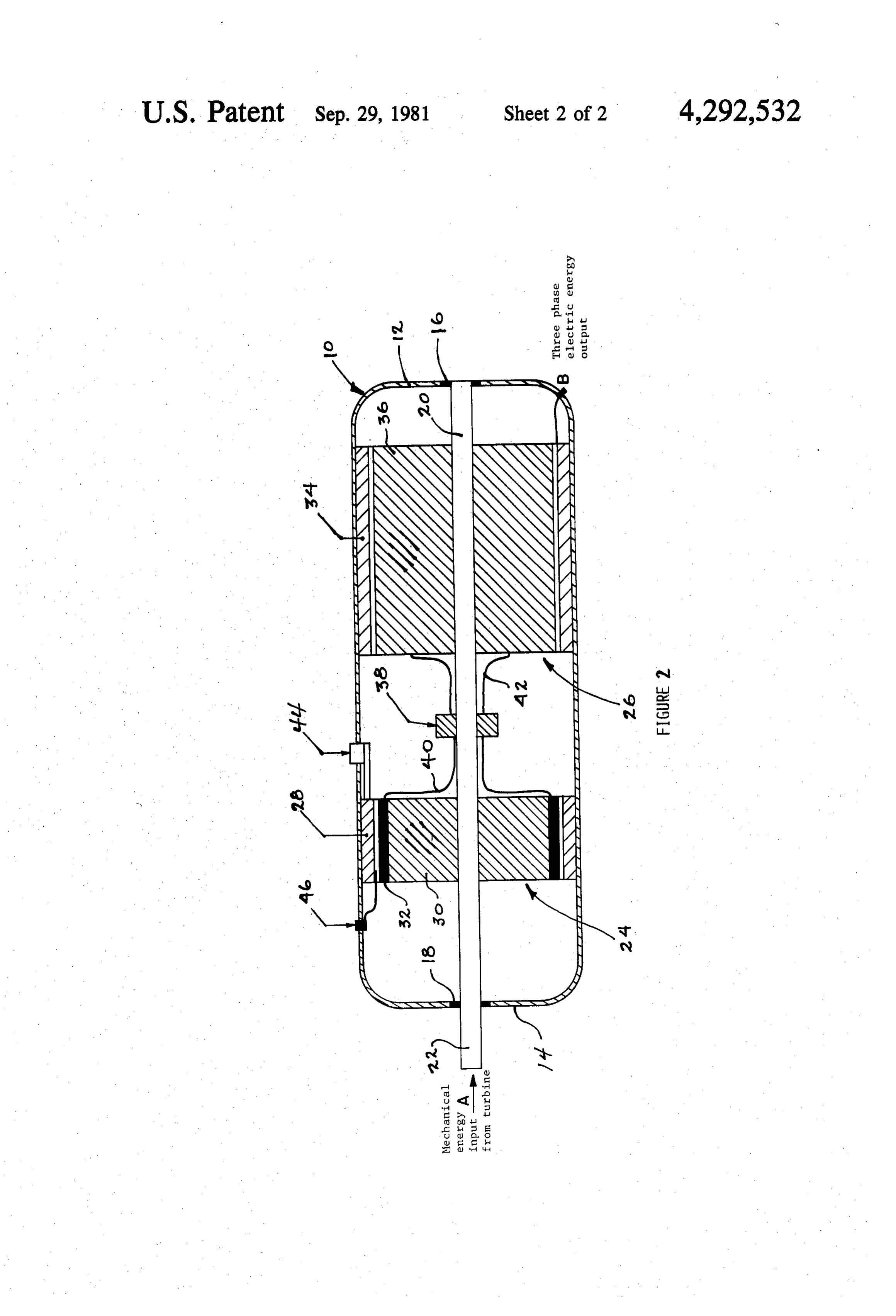
the third power of the speed. An electric generator : BRIEF DESCRIPTION OF THE DRAWINGS system coupled to such a turbine must satisfy three basic 10 FIG. 1 is a graph showing a power vs speed curve to requirements. First, the normalized power vs speed curve of the generator should intercept the power vs explain the basic principle of the present invention; and speed curve of the turbine in such a way as o assure a FIG. 2 is a sectional schematic representation of a stable operating point around the design speed. Se system made in accordance with the present invention. condly, the system should be free of static torque to be 15 FIG. 1 represents a normalized relation between able to start without help and, finally, it should be main power and speed in the third power of the speed when tenance free for the design life of the unit. a propeller type turbine is used to convert wind and It is an object of the present invention to provide a hydraulic energy to mechanical energy. That is if two-stage electric generator system to convert mechan Pm = mechanical power available at speed a) and ical energy from a wind or hydraulic driven turbine into 20 Pmn=mechanical power available at nominal design electric energy. Such system comprises: an exciter gen speed on then erator and a main generator, the exciter generator con sisting of permanent magnet means mounted to the system housing and of a rotor rotatably supported on a shaft rotatable in the housing; the rotor is made of non 25 magnetic material to eliminate cogging and static torque associated with permanent magnet excitation Referring to FIG. 2, a two-stage electric generator and includes a one-phase winding distributed around system the circumference thereof; the main generator consists shown made in accordance with the present invention is where mechanical energy input, such as ob of a three-phase stator winding on a magnetic core 30 mounted to the housing and of a pole-type rotor rotat tained from a turbine of the type described above, is fed ably supported on the shaft and having a winding at A and a three-phase electric energy output is taken wound on a magnetic core; a rectifying bridge is out at B. The reference numeral 10 designates generally mounted on the shaft while first means electrically con an enclosed housing for the two-stage electric generator nect the one phase winding to the rectifying bridge and 35 system. The opposite end sections 12 and 14 of the second means electrically connect the rectifying bridge housing 10 support ball-bearing assemblies 16 and 18, to the winding of the main generator rotor whereby respectively, which engage a rotatable shaft 20 which is rotation of the shaft as a result of mechanical energy driven at its end 22 by being appropriately connected to applied thereon generates a three-phase electric energy a turbine (not shown). Housing 10 encloses an exciter output from the stator winding. generator 24 and a main generator 26. The exciter gen There are a series of possible applications for the erator consists of permanent magnet assembly 28 which system of the present invention. For example, in the may consist of one or more rings and which is mounted case of heating in the far north where wind power is to the inside wall of the housing envelope and of a rotor available, the present system may be mounted to a 30 which is rotatably mounted to the shaft 20. The rotor tower equipped with a wind turbine and be perma 45 30 is made of a non-magnetic material to eliminate the nently connected to some heating element so that wind cogging and static torque which are usually associated energy may be converted into hot water at the rate with permanent magnet excitation. Rotor 30 includes a available in the wind. Such heating can be three-phase one phase winding 32 distributed around the circumfer power if the heat sink is near or by D.C. transmission if ence thereof.
the heat sink is far. 50
The present system is also applicable for pumping winding The main generator 26 consists of a three-phase stator water wherein the D.C. wind power, made possible in inside wall on a magnetic core 34 which is mounted to the the above described example, can be applied to a D.C. of the housing envelope and of a pole-type permanent magnet or series motor pump inside a shaft rotor 36, salient or not, which is rotatably supported on to make water available where wind is available. 55 the shaft 20. The rotor has a winding wound on a mag The present system may be used with a water propel netic core.
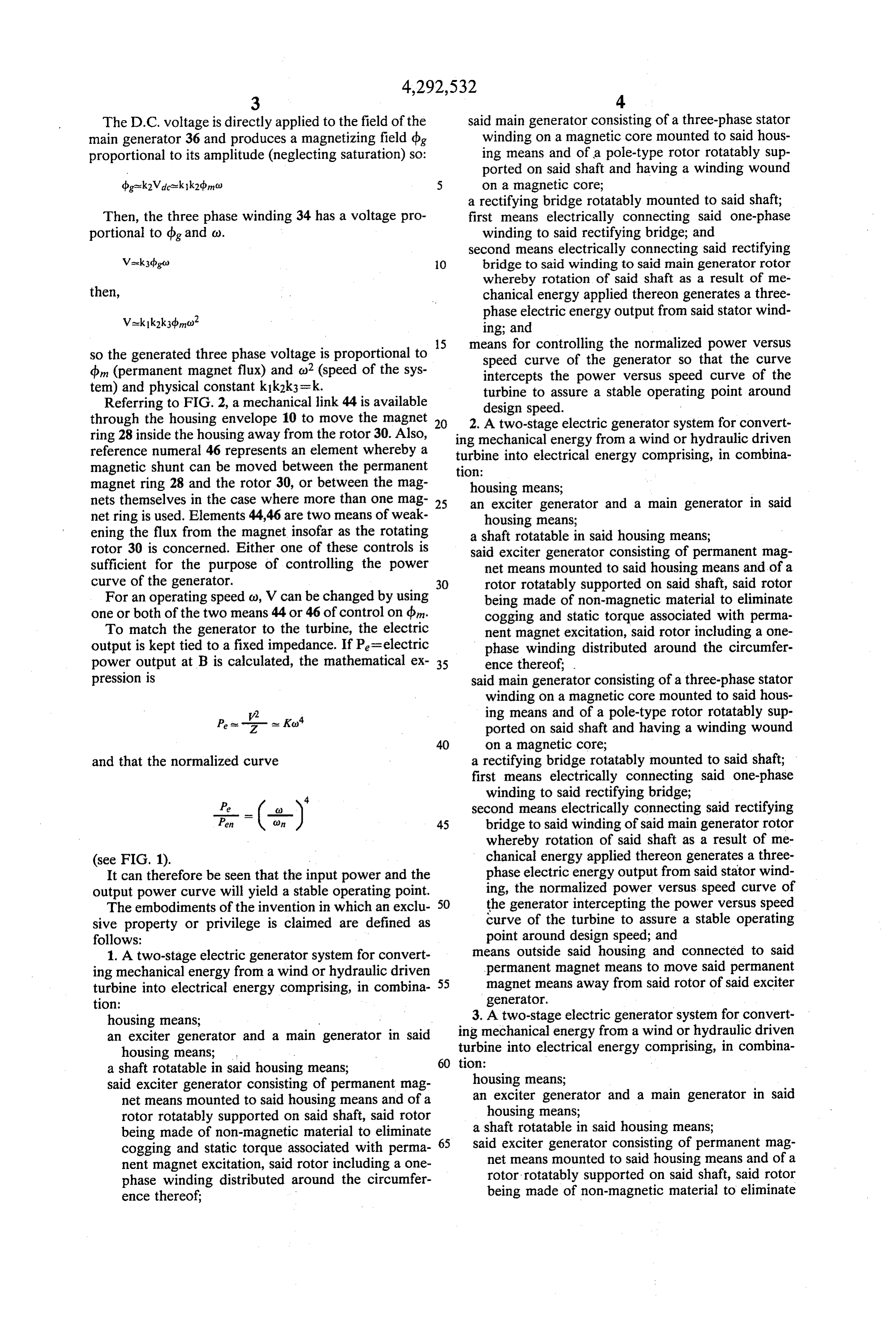
ler type turbine under a constant water head (small dam Also, rotatably mounted to shaft 20 is a rectifying power); it can be made to deliver approximately line bridge 38 which is electrically connected at 40 and 42 to frequency when using an electric controller to maintain the one-phase winding 32 and to the winding of the output power and input power equal by shunting output 60 main generator rotor 36, respectively. power to heating anything (even a river) when output is With the permanent magnet assembly 28 in place and not required elsewhere. the rotor rotating, an alternating voltage is available in Also, if wind or water are available and if the gener the single phase winding 30. This voltage is rectified by ated energy is not usable at the site, it can convert to the rotating bridge 38 and the rectified voltage is pro other energy, mostly by chemical means, such as elec 65 portional to the speed, that is Vdc =k, dbmc), where trolysis. : Vdc = rectified voltage from exciter Other objects and further scope of applicability of the dbm=flux of magnet .. present invention will become apparent from the de a) = rotating speed of the system.
Page 5
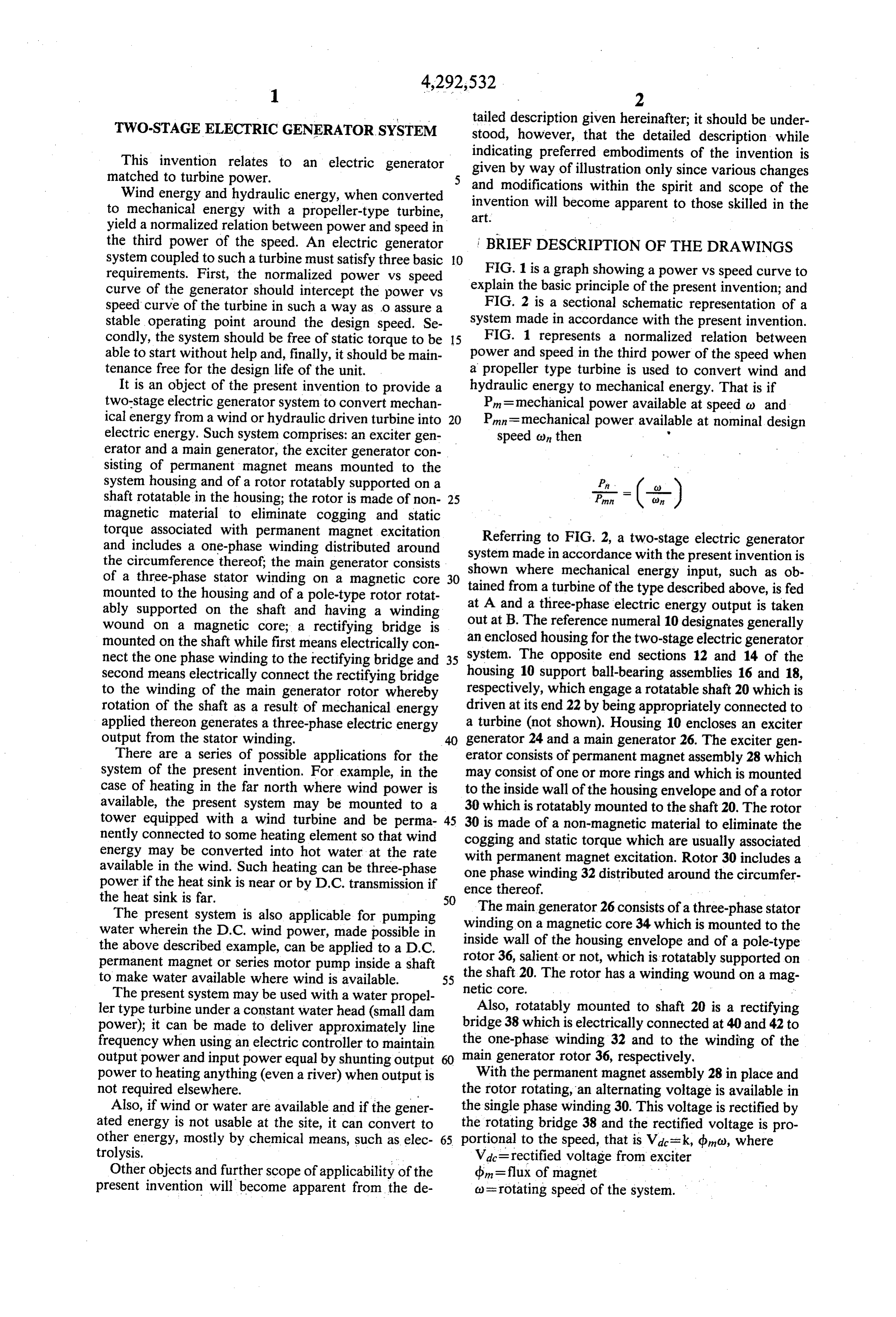
The D.C. voltage is directly applied to the field of the said main generator consisting of a three-phase stator main generator 36 and produces a magnetizing field dig winding on a magnetic core mounted to said hous proportional to its amplitude (neglecting saturation) so: ing means and of a pole-type rotor rotatably sup ported on said shaft and having a winding wound on a magnetic core;
a rectifying bridge rotatably mounted to said shaft;
Then, the three phase winding 34 has a voltage pro first means electrically connecting said one-phase portional to dog and c). winding to said rectifying bridge; and second means electrically connecting said rectifying
Vek3d go) 10 bridge to said winding to said main generator rotor whereby rotation of said shaft as a result of me then, chanical energy applied thereon generates a three phase electric energy output from said stator wind ing; and so the generated three phase voltage is proportional to 15 means for controlling the normalized power versus dm (permanent magnet flux) and o? (speed of the sys speed curve of the generator so that the curve intercepts the power versus speed curve of the tem) and physical constant k1k2k3=k. turbine to assure a stable operating point around Referring to FIG. 2, a mechanical link 44 is available design speed.
through the housing envelope 10 to move the magnet 20 2. A two-stage electric generator system for convert ring 28 inside the housing away from the rotor 30. Also, ing mechanical energy from a wind or hydraulic driven reference numeral 46 represents an element whereby a turbine into electrical energy comprising, in combina magnetic shunt can be moved between the permanent tion:
magnet ring 28 and the rotor 30, or between the mag housing means;
nets themselves in the case where more than one mag 25 an exciter generator and a main generator in said net ring is used. Elements 44,46 are two means of weak housing means;
ening the flux from the magnet insofar as the rotating a shaft rotatable in said housing means; rotor 30 is concerned. Either one of these controls is said exciter generator consisting of permanent mag sufficient for the purpose of controlling the power net means mounted to said housing means and of a curve of the generator. 30 rotor rotatably supported on said shaft, said rotor For an operating speed co, V can be changed by using being made of non-magnetic material to eliminate one or both of the two means 44 or 46 of control on dn. cogging and static torque associated with perma To match the generator to the turbine, the electric nent magnet excitation, said rotor including a one output is kept tied to a fixed impedance. If Pe=electric phase winding distributed around the circumfer power output at B is calculated, the mathematical ex 35 ence thereof;
pression is said main generator consisting of a three-phase stator winding on a magnetic core mounted to said hous /2 ing means and of a pole-type rotor rotatably sup
P- - - - - Ko" ported on said shaft and having a winding wound 40 on a magnetic core;
and that the normalized curve a rectifying bridge rotatably mounted to said shaft; first means electrically connecting said one-phase winding to said rectifying bridge;
second means electrically connecting said rectifying 45 bridge to said winding of said main generator rotor whereby rotation of said shaft as a result of me (see FIG. 1). chanical energy applied thereon generates a three It can therefore be seen that the input power and the phase electric energy output from said stator wind output power curve will yield a stable operating point. ing, the normalized power versus speed curve of The embodiments of the invention in which an exclu 50 the generator intercepting the power versus speed sive property or privilege is claimed are defined as curve of the turbine to assure a stable operating follows: point around design speed; and 1. A two-stage electric generator system for convert means outside said housing and connected to said ing mechanical energy from a wind or hydraulic driven permanent magnet means to move said permanent turbine into electrical energy comprising, in combina 55 magnet means away from said rotor of said exciter tion: generator.
housing means; 3. A two-stage electric generator system for convert an exciter generator and a main generator in said ing mechanical energy from a wind or hydraulic driven housing means; turbine into electrical energy comprising, in combina a shaft rotatable in said housing means; 60 tion: -
said exciter generator consisting of permanent mag housing means;
net means mounted to said housing means and of a an exciter generator and a main generator in said rotor rotatably supported on said shaft, said rotor housing means;
being made of non-magnetic material to eliminate 65 asaid shaft rotatable in said housing means; exciter generator consisting of permanent mag cogging and static torque associated with perma nent magnet excitation, said rotor including a one net means mounted to said housing means and of a phase winding distributed around the circumfer rotor rotatably supported on said shaft, said rotor ence thereof; being made of non-magnetic material to eliminate
Page 6
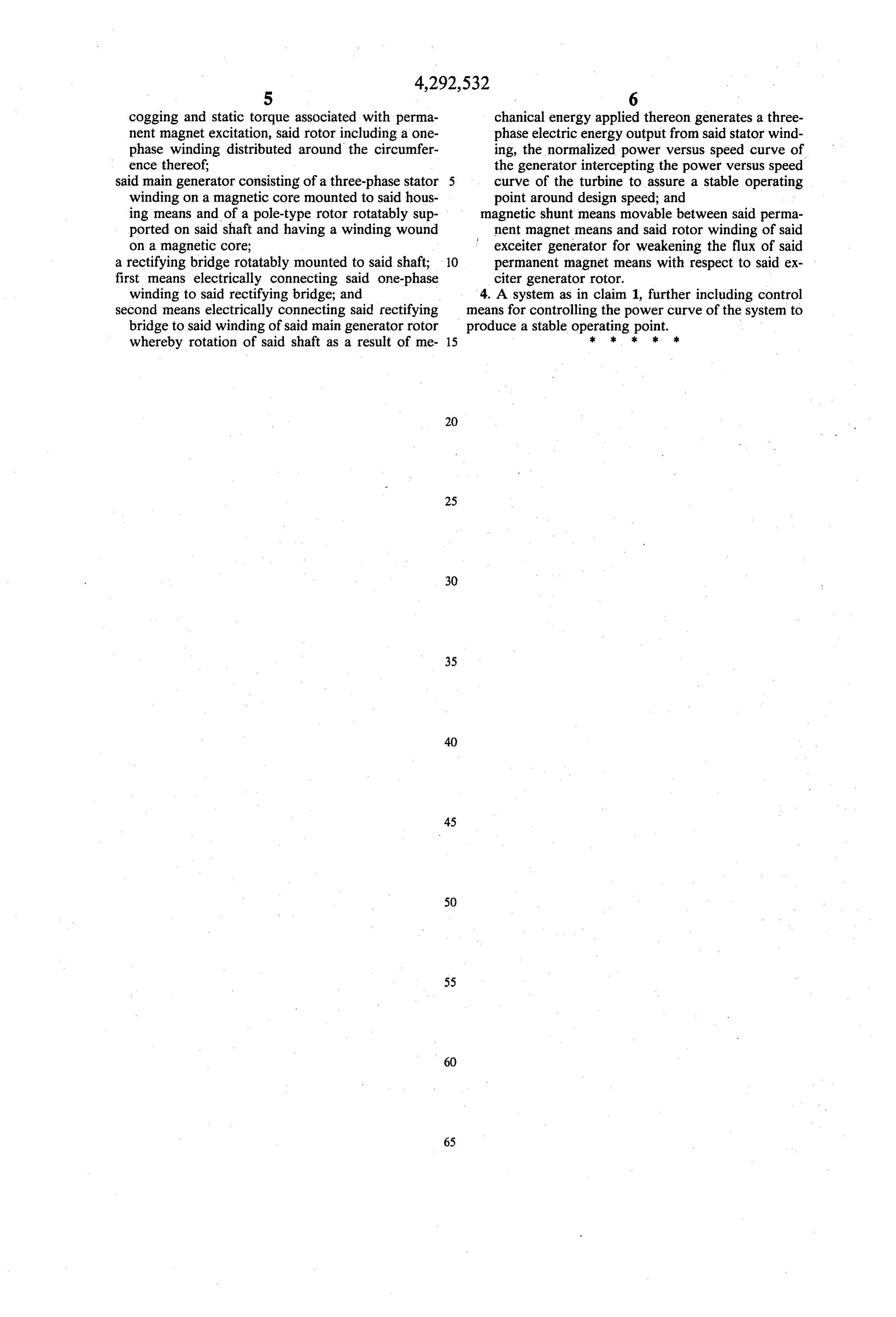
cogging and static torque associated with perma chanical energy applied thereon generates a three nent magnet excitation, said rotor including a one phase electric energy output from said stator wind phase winding distributed around the circumfer ing, the normalized power versus speed curve of ence thereof; the generator intercepting the power versus speed said main generator consisting of a three-phase stator curve of the turbine to assure a stable operating winding on a magnetic core mounted to said hous point around design speed; and ing means and of a pole-type rotor rotatably sup magnetic shunt means movable between said perma ported on said shaft and having a winding wound f nent magnet means and said rotor winding of said on a magnetic core; exceiter generator for weakening the flux of said a rectifying bridge rotatably mounted to said shaft; O permanent magnet means with respect to said ex first means electrically connecting said one-phase citer generator rotor.
winding to said rectifying bridge; and 4. A system as in claim 1, further including control second means electrically connecting said rectifying means for controlling the power curve of the system to bridge to said winding of said main generator rotor produce a stable operating point. whereby rotation of said shaft as a result of me 15
Provenance
- Collection
- Cited prior art
- Original PDF
- patentimages.storage.googleapis.com →
- Filed
- 1980-04-02
- Pages
- 6
- Method
- pdftotext (the PDF's own text layer) + pdftoppm 300dpi page scans
- Source
- Google Patents bibliographic record
- Granted
- 1981-09-29
- Inventors
- Adrien Leroux; HOP Consulab Inc
- Transcribed from
- patentimages.storage.googleapis.com →