patent · US2806160
Rotor and method of making the same
10 September 1957
Page 1
Drawing sheet — no readable text.
Page 2
Drawing sheet — no readable text.
Page 3
United States Patent Office Patented Sept.2,806,166
sembly are combined with thermal treatment to the end that the parts that are easily and rapidly assembled are 2,806,160 finally incorporated in the rotor to form a solid or rigid ROOR AND METHG) OF R/AKNG THE SAME unitary structure wherein the component parts are not subject to shifting or relative movement, even under
Maurice W. Brainard, Montebello, Calif., assignor of one severe operating conditions.
half to O'Keefe & Merritt Company, Los Angeles, The rotor which is the subject of this invention pref Calif., a corporation of California erably includes one or more magnets, preferably perma Application October 27, 1952, Seria No. 317,107 nent magnets, in a cage that includes diametrically oppo O site polar parts, frame elements extending between the 6 Claims. (C. 310-156) polar parts and tie members connecting the polar parts and the frame elements. The assembly of the cage and magnets considered broadly is completed by an abut ment
This invention has to do with a rotor or structure 5 and solidly engaged with the magnet or magnets to positively adapted to rotate as it is operated, and with a method hold them in working position relative to the of making such a structure, it being a general object cage, and particularly with reference to the polar parts of the invention to provide a simple, practical, rigid, rotor of the cage. In the preferred construction the polar parts construction and a simple, dependable and practical of the cage present inclined seats or wedge parts and the method of making such a rotor. ends of the magnets engage the polar seats and are wedged tightly into engagement with them. In a pre
The rotor which is the subject of the present invention ferred arrangement a plurality of magnets, as for in is of the type wherein a plurality of separate or indi stance two magnets, is provided. The magnets extend vidually formed parts is assembled into a unit, which unit parallel with each other between diametrically opposite is intended or adapted to be rotated at such speed that polar pressures or strains develop tending to shift, or result in 25 so thatparts,
and are spaced apart, or from one another, single abutment between the magnets and ex relative movement between, parts of the unit. In a typi tending diametrically of the rotor holds the magnets in cal, practical application of the invention, the rotor pro wedging engagement with the seats of the polar parts. vided may be the rotating element of an electric machine In a preferred form of the invention the magnets are sec such, for example, as the rotor of a generator, or the like. In view of this situation the structure hereinafter 30 betweenin spaced tional form and sections of the magnets are arranged frame elements of the cage and the polar referred to specifically will be the rotor of an electric machine, and the parts incorporated in the rotor will in entially of the rotor, soconstruction parts are of laminated and extend circumfer clude, essentially, a cage carrying permanent magnets. It with a plurality of magnets. Morepolarthat each part cooperates specifically, the in is to be understood that as the broader principles of the vention provides a body in connection with the assembly invention are applied to other situations the parts may 35 of magnets, cage, and abutment, and in a typical case the vary from those characteristic of an electric machine, and body is made up of end plates that occur at opposite therefore the specific example hereinafter set forth is ends of the assembly, and wedges related to and coupling to be construed broadly, and not in a limited manner.
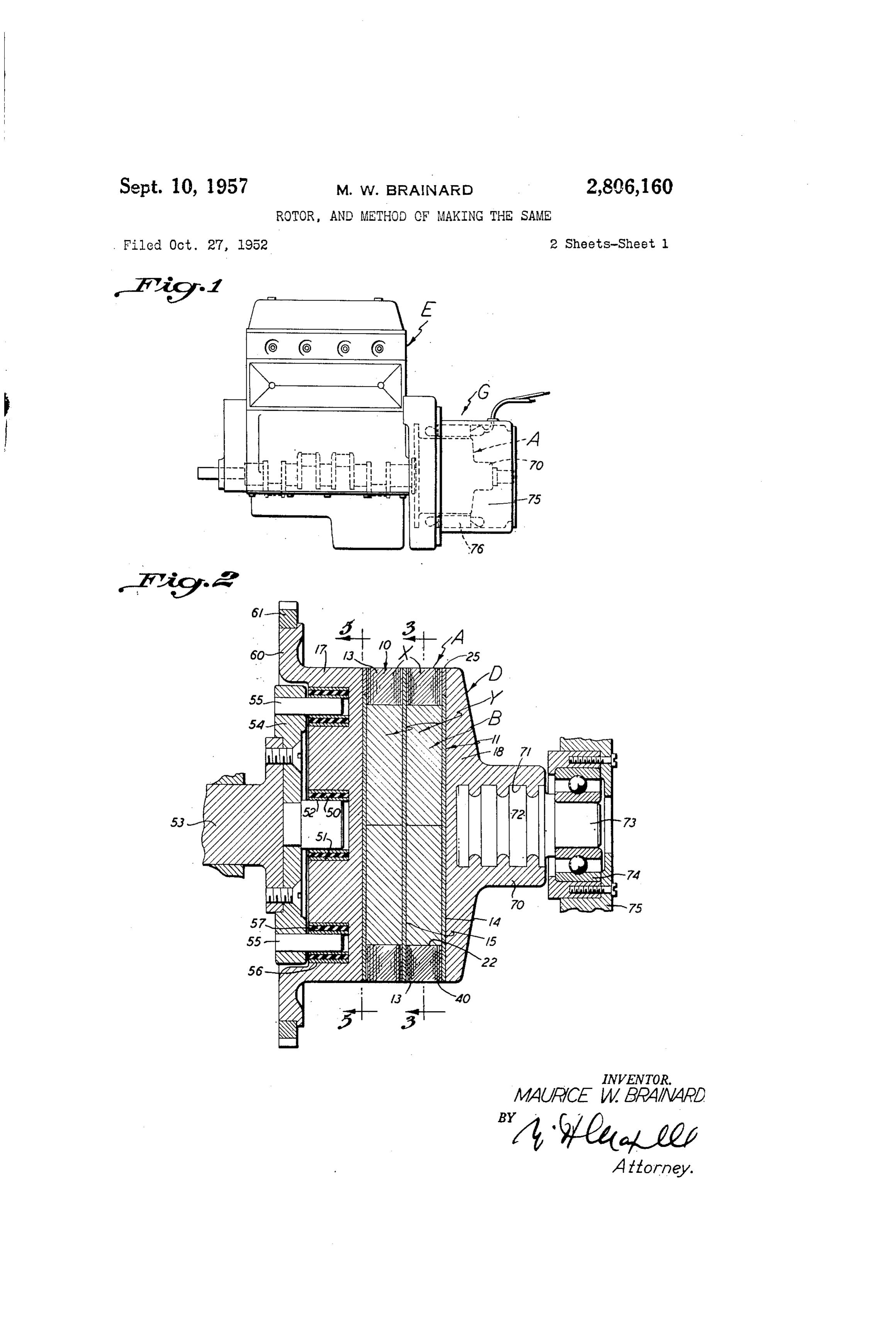
It is a general object of the present invention to pro the other end plates so that they are in fixed relation to each and relative to the assembly. The end plates of vide a rotor characterized by a cage, a magnet in the 40 the rotor present elements of the structure that facili cage, and an abutment engaged with the magnet and tate application of the rotor to or its incorporation in holding it tight in the cage. a machine such as a generator, or the like. It is another object of the invention to provide a rotor The various objects and features of my invention will of the general character referred to wherein the magnet has wedging engagement with the rotor and is backed up 45 be tion fully understood from the following detailed descrip of a typical preferred form of the invention and a by the abutment, so that the abutment positively main typical manner of carrying out the method, throughout tains the magnet tightly wedged in the cage, and in con which description reference is made to the accompany tact therewith. ing drawings, in which:
It is another object of the invention to provide a rotor of the general character referred to wherein the magnet 50 of Fig. an 1 is a side elevation of a prime mover, in the form internal combustion engine, coupled to and driving is wedged between diametrically opposite pole parts of a generator, the the rotor while a single abutment holds the magnet invention. Fig. 2rotor of which embodies the present is a longitudinal, central, sectional wedged with the pole parts. view of the rotor and certain of the parts of the structure It is a further object of this invention to provide a shown in Fig. 1. Fig. 3 is a detailed transverse sectional rotor of the general character referred to wherein the rotor includes a plurality of spaced magnets with a single 3-3 onthe view of
Fig.
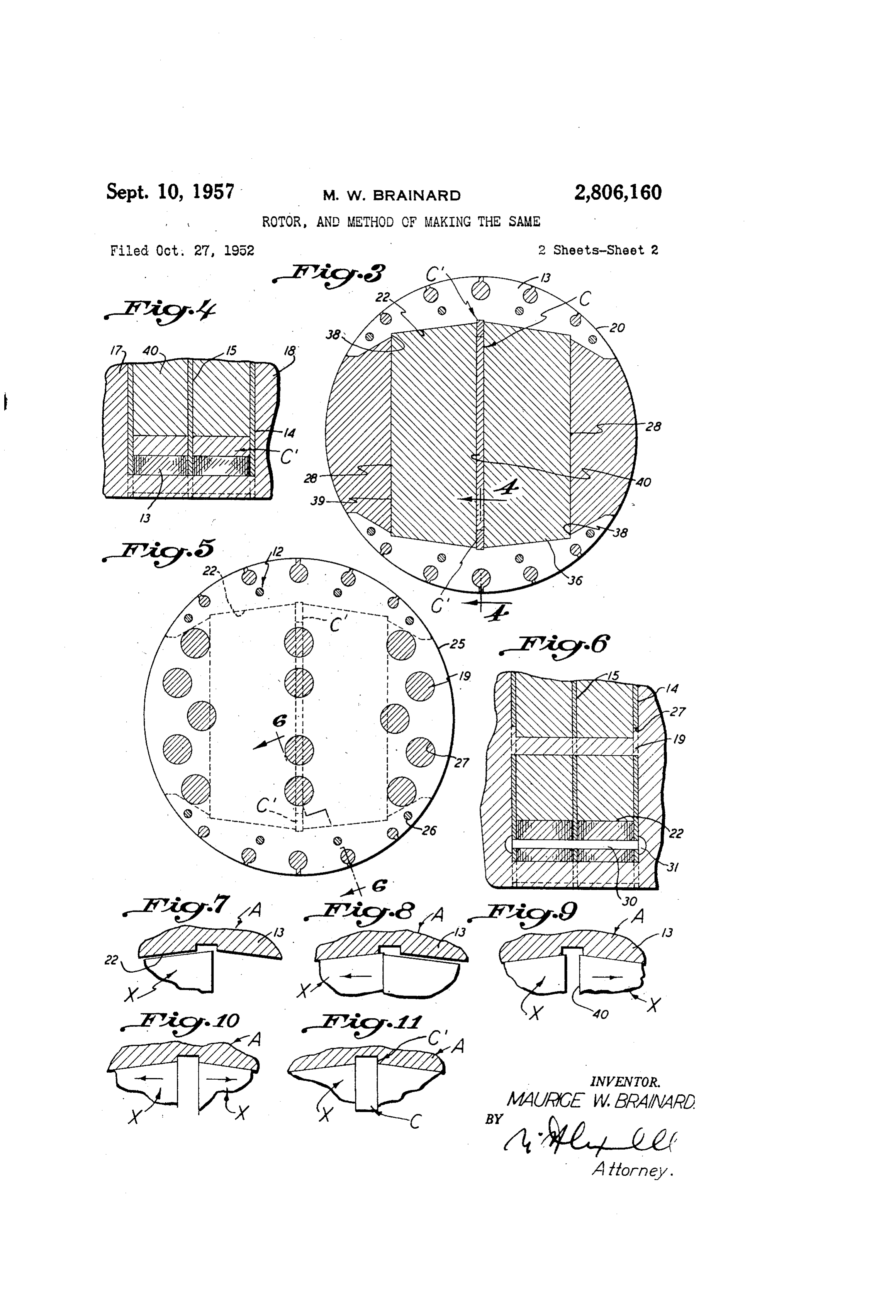
rotor being a view taken as indicated by line 2. Fig. 4 is an enlarged detailed, sectional abutment engaging the magnets and holding them in wedg view of a portion of the rotor, being a view taken sub ing engagement with the pole parts of the rotor. stantially as indicated by line 4-4 on Fig. 3. Fig. 5 It is another object of the present invention to pro vide a rotor of the general character referred to wherein 60 isa view a detailed, transverse, sectional view of the rotor, being taken as indicated by line 5-5 on Fig. 2. Fig. 6 the assembly formed by the cage, magnet, and abut is an enlarged ment, is combined with a body characterized by end plates rotor, being a detailed sectional view of a portion of the at opposite ends of the assembly and web parts that line 6-6 on Fig. 5, and substantially view taken as indicated by
Figs. 7 to 11, inclusive, are connect the end plates holding them tight on the as somewhat diagrammatic views illustrating steps per sembly. 65 formed in carrying out the method of the present inven It is another object of the present invention to provide tion and illustrating in particular the manner in which a rotor of the general character referred to wherein the the magnets are assembled with the cage, one after an body and the abutment are integrally joined, being pref other, or are wedged into the cage and then made tight erably part of a single casting. by an abutment engaged between the magnets. It is another object of the present invention to pro 70 The present invention is concerned, generally, with vide a method of making a rotor of the general character a rotor construction, and it is concerned with a method referred to wherein simple, easily executed steps of as of making such a rotor construction. It is believed that
Page 4
the method as provided by the invention will be under In practice the number of frame elements employed in stood and immediately apparent from a consideration the rotor may vary widely, depending upon the size or of the structure and the following description of the complexity of the rotor. To illustrate the general con handling of the structure. struction contemplated by the invention, a rotor is illus The rotor which is the subject of the present invention trated having end frame members 14 occurring at the may, in accordance with the broader principles of the ends of the frame and an intermediate frame member invention, be varied widely inform and construction and 15 located between the end elements. In this case each for purpose of example it is disclosed. and referred to as polar part is divided into two sections X and each mag the rotor. of an electric machine, such as a generator G, net B is divided into two sections Y. It is to be under and that electric machine is shown coupled to and O stood that if additional intermediate frame elements. 15 adapted to be driven by a prime mover, in the form of are employed, the polar parts and magnets may be ac an engine. E. The rotor considered, broadly includes a cordingly divided into more sections than illustrated. cage A, one or more magnets. B: located in and engaged In the preferred construction each frame element has With the cage A, and one or more abutments: C related an outer edge or peripheral portion 25 curved to be con to or engaged with the magnets holding them tight, pref. 5 centric with the axis of the rotor, and it has a plurality erably in wedging engagement with - parts of the cage. of openings 26 that pass the tie members 2 and a plural More specifically, and as disclosed in the drawings, the ity of parts 27 that pass the web parts of the body D. rotor includes a body D combined with or supporting In the case of the parts 27 that pass the web parts of the assembly formed of the cage A, magnets. B and abut the body, there may be a wide variation- as to factors ments C. 20 such as size, shape and location. In the drawings open The cage in the preferred form of the present-invention ings 27 of different sizes are illustrated and some are -lo is characterized by pole pieces. or polar parts 10, frame cated in the peripheral portions of the frame elements elements 11 extending between the polar parts, and tie and open at the periphery of the rotor, while others are members 12 connecting the frame elements and polar located inward of the periphery 25. In the particular parts. In the particular adaptation of the invention. 25 case illustrated certain of the openings 27 are located herein. Set. forth there are two-polar parts, and these are outward of or from the outer sides 28 of the magnet Sec located diametrically opposite, each other, and there are. tions Y while others are located in a line or series ex Several frame elements between which sections 13. of the tending diametrically of the rotor and parallel with the polar parts. occur or are confined. In the particular case magnet sections to cccur opposite or in register with the illustrated there are end, frame elements. 14 and an inter 30 abutments C located between the magnet sections. mediate frame element 15. The several-frame elements: The tie members 2 may in practice vary widely in are preferably alike and they are disc-shaped parts con number, size and arrangement. In the case illustrated the centric with the major central axis of the rotor. The . tie members 52 are confined to the portion of the cage tie members 2 extend axially, of the rotor through the A where the polar parts 13 occur and each tie member frame elements and the polar parts and tie these ele includes a rod 30 extending axially through the assembly ments together. Further, in the particular rotor illus of polar part sections X and frame elements while trated there are like magnets B each made up of sections heads 32 on the ends of the rod 30 outward of the end occurring between frame elements of the cage. The frame members secure the parts assembled as clearly Sections of the two-magnets are engaged by abutments C illustrated in Fig. 6 of the drawings. So, that each abutment engages and holds at least two 40 The magnet sections Y are elongate in form and the magnet sections. The body D considered generally is two sections of the two magnets occurring between ad characterized by end plates 17 and 18 and has web por jacent frame elements are arranged parallel with each tions 19 extending axially of the rotor and between the other and extend between the polar parts 3 of the cage end plates to hold the end plates tight on the assembly. and are spaced in opposite directions from the central formed by the cage, magnets and abutments. axis of the rotor. Through this construction the sec The polar parts 13 of cage. A are preferably alike and 45 tions of the magnets are parallel and spaced apart and in the case illustrated they are diametrically opposite their ends 36 oppose and are engaged with the seats 22 each other, that is, they are at diametrically opposite. provided in the polar parts 3 of the cage. sides of the rotor. Each polar part 13 has an outer pe In accordance with the present invention the magnets riphery. 20 curved concentric with the axis of the rotor. 50 or magnet sections and the polar parts of the cage are and each polar part is sectional, that is, it has portions or related so that there is wedging engagement between Sections occurring between the frame elements as clearly . these parts. In the preferred form of the invention the illustrated in Fig. 2 of the drawings. In the preferred magnet Sections-wedge between opposed parts or seats 22 construction the polar parts 13 are of laminated construc of the polar parts. In the construction illustrated the tion, that is, they are made up of a plurality of super 55 magnet sections Y wedge radially outward between op imposed plates, which plates are of magnetic material, posed portions of the polar parts and when two magnets Say, for example, iron or soft steel. Each section of each are employed, as illustrated in the drawings, the mag polar part is of such extent circumferentially of the nets wedge outwardly in opposite directions relative to rotor as to present inwardly facing seats 22 that are en the center of the rotor. In the case illustrated the gaged by corresponding ends of magnet sections that are 60 seats 22 at the inner sides of the two polar parts 13 ac between the frame elements of the cage and located in commodating opposite ends 36 of a magnet section Y opposite directions from the central axis of the rotor in wardlyare pitched or inclined relative to each other to be out convergent, that is, convergent in a direction in a direction normal to that in which the polar parts are which the magnet section is removed from the central disposed or spaced apart relative to the central axis of the rotor. 65 axis of the rotor.
The frame elements 1 of the cage are preferably flat In the preferred construction the seats 22 of the disc-shaped plate-like parts and in a preferred form of polar parts are flat and smooth and extend outward to and terminate at inwardly facing shoulders 38 at the inner the invention they are formed of sheet material that is sides of the polar parts 13. The ends 36 of the magnet non-magnetic, for instance they may be formed of stain less steel, or other comparable non-magnetic material. 70 Sections inclined are likewise preferably flat and smooth- and are or pitched to correspond to the inclination or
The frame elements it are disposed in planes normal pitch of the seats 22. The parts just referred to are re to the longitudinal axis of the rotor and extend between lated and proportioned so that when the magnet sections the polar parts 13. At the polar parts 3 the frame are in their outermost positions, or are fully and tightly elements enter between the sections of the polar parts, as 75 engaged in the cage, having wedging engagement with clearly illustrated in Fig. 2 of the drawings. the polar parts of the cage, the outer-sides 28 of the
Page 5
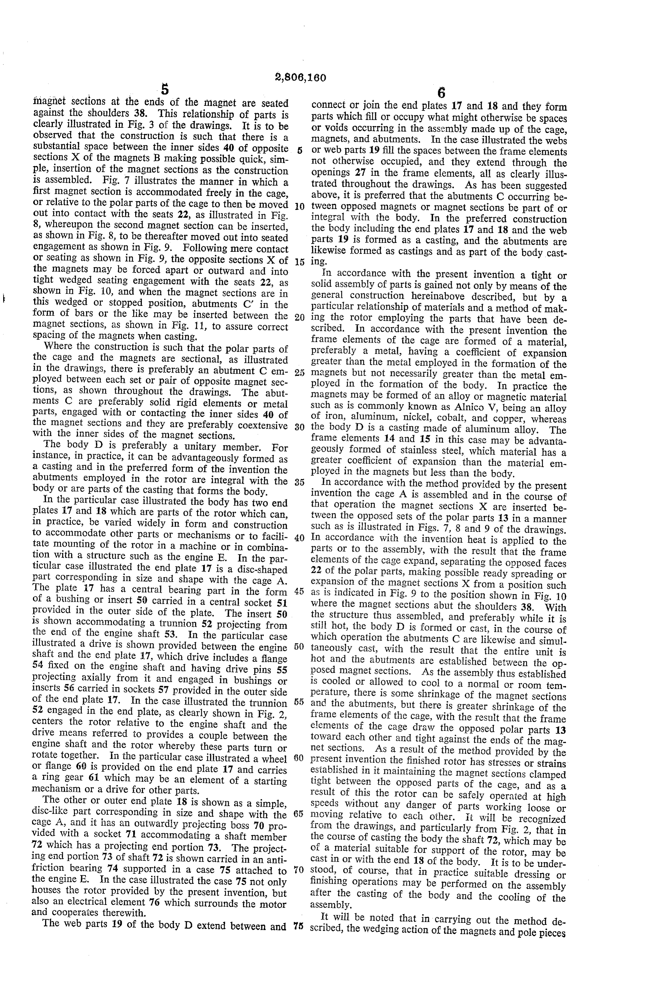
imagnet sections at the ends of the magnet are seated connect or join the end plates 17 and 18 and they form against the shoulders 38. This relationship of parts is clearly illustrated in Fig. 3 of the drawings. It is to be parts which fill or occupy what might otherwise be spaces or voids occurring in the assembly made up of the cage, observed that the construction is such that there is a magnets, and abutments. In the case illustrated the webs substantial space between the inner sides 40 of opposite or web parts sections X of the magnets B making possible quick, sim not otherwise19 occupied, fill the spaces between the frame elements and they extend through the ple, insertion of the magnet sections as the construction openings 27 in the frame elements, all as clearly illus is assembled. Fig. 7 illustrates the manner in which a trated throughout the drawings. As has been Suggested first magnet section is accommodated freely in the cage, above, it is preferred that the abutments C occurring be or relative to the polar parts of the cage to then be moved O tween opposed magnets or magnet sections be part of or out into contact with the seats 22, as illustrated in Fig.
8, whereupon the second magnet section can be inserted, integral with the body. In the preferred construction as shown in Fig. 8, to be thereafter moved out into seated parts 19 isincluding the body formed the end plates 17 and 18 and the web as a casting, and the abutments are engagement as shown in Fig. 9. Following mere contact likewise formed as castings and as part of the body cast or seating as shown in Fig. 9, the opposite sections X of 1ng.
the magnets may be forced apart or outward and into In accordance with the present invention a tight or tight wedged seating engagement with the seats 22, as solid assembly of parts is gained not only by means of the shown in Fig. 10, and when the magnet sections are in general construction hereinabove described, but by a this wedged or stopped position, abutments C in the particular relationship of materials and a method of mak form of bars or the like may be inserted between the 20 ing the rotor employing the parts that have been de magnet Sections, as shown in Fig. 11, to assure correct scribed. In accordance with the present invention the spacing of the magnets when casting. frame elements of the cage are formed of a material, Where the construction is such that the polar parts of preferably the cage and the magnets are sectional, as illustrated greater thana the metal, having a coefficient of expansion metal employed in the formation of the in the drawings, there is preferably an abutment C em ployed between each set or pair of opposite magnet sec magnets but not necessarily greater than the metal em tions, as shown throughout the drawings. The abut ployed magnets in the formation of the body. In practice the may be formed of an alloy or magnetic material ments C are preferably solid rigid elements or metal parts, engaged with or contacting the inner sides 40 of such as is commonly known as Alnico V, being an alloy of iron, aluminum, nickel, cobalt, and copper, whereas the magnet sections and they are preferably coextensive 30 the body D is a casting made of aluminum alloy. The with the inner sides of the magnet sections.
The body D is preferably a unitary member. For geouslyelements frame 14 and 15 in this case may be advanta formed of stainless steel, which material has a instance, in practice, it can be advantageously formed as greater a casting and in the preferred form of the invention the ployed incoefficient the of expansion than the material em magnets but less than the body.
abutments employed in the rotor are integral with the 35 In accordance with the method provided by the present body or are parts of the casting that forms the body.
In the particular case illustrated the body has two end that operation the magnet sectionsand invention the cage A is assembled in the course of plates 17 and 18 which are parts of the rotor which can, tween the opposed sets of the polar partsare X inserted be 13 in a manner in practice, be varied widely in form and construction to accommodate other parts or mechanisms or to facili 40 such
as is illustrated in Figs. 7, 8 and 9 of the drawings.
accordance with the invention heat is applied to the tate mounting of the rotor in a machine or in combina parts or to the assembly, with the result that the frame tion with a structure such as the engine E. In the par elements ticular case illustrated the end plate 17 is a disc-shaped 22 of the ofpolar the cage expand, separating the opposed faces parts, making possible ready spreading or part corresponding in size and shape with the cage A.
The plate 17 has a central bearing part in the form 45 as is indicated in magnet expansion of the sections X from a position such
Fig. 9 to the position shown in Fig. 10 of a bushing or insert 50 carried in a central socket 51 provided in the outer side of the plate. The insert 50 wherethe the magnet sections abut the shoulders 38. With structure thus assembled, and preferably while it is is shown accommodating a trunnion 52 projecting from Still hot, the body the end of the engine shaft 53. In the particular case which operation theDabutments is formed or cast, in the course of C are likewise and simul illustrated a drive is shown provided between the engine 50 taneously cast, with the result that the entire unit is shaft and the end plate 7, which drive includes a flange hot and the abutments are established between the op 54 fixed on the engine shaft and having drive pins 55 posed magnet Sections. As the assembly thus established projecting axially from it and engaged in bushings or is cooled or allowed to cool to a normal or room tem inserts 56 carried in sockets 57 provided in the outer side perature, there is some shrinkage of the magnet sections of the end plate 17. In the case illustrated the trunnion 55 and the abutments, 52 engaged in the end plate, as clearly shown in Fig. 2, frame elements of thebutcage, there is greater shrinkage of the centers the rotor relative to the engine shaft and the elements of the cage draw with the result that the frame the opposed polar parts 13 drive means referred to provides a couple between the engine shaft and the rotor whereby these parts turn or toward net each other and tight against the ends of the mag sections. As a result of the method provided by the rotate together. In the particular case illustrated a wheel 50 present invention the finished rotor has stresses or strains or flange 60 is provided on the end plate 17 and carries established in it maintaining the magnet sections clamped a ring gear 61 which may be an element of a starting tight between the opposed parts of the cage, and as a mechanism or a drive for other parts. result of this the rotor can be safely operated at high The other or outer end plate 18 is shown as a simple, disc-like part corresponding in size and shape with the 65 Speeds Without any danger of parts working loose or moving relative to each other. it will be recognized cage A, and it has an outwardly projecting boss 70 pro from the drawings, and particularly from Fig. 2, that in vided with a socket 71 accommodating a shaft member the course of casting the body the shaft 72, which may be 72 which has a projecting end portion 73. The project of a material suitable for support of the rotor, may be ing end portion 73 of shaft 72 is shown carried in an anti cast in or with the end 18 of the body. It is to be under friction bearing 74 supported in a case 75 attached to 70 stood, of course, that in practice suitable dressing or the engine E. In the case illustrated the case 75 not only finishing operations may be performed on the assembly houses the rotor provided by the present invention, but after the casting of the body and the cooling of the also an electrical element 76 which surrounds the motor assembly.
and cooperates therewith. It will be noted that in carrying out the method de The web parts 19 of the body D extend between and 75 Scribed, the wedging action of the magnets and pole pieces
Page 6
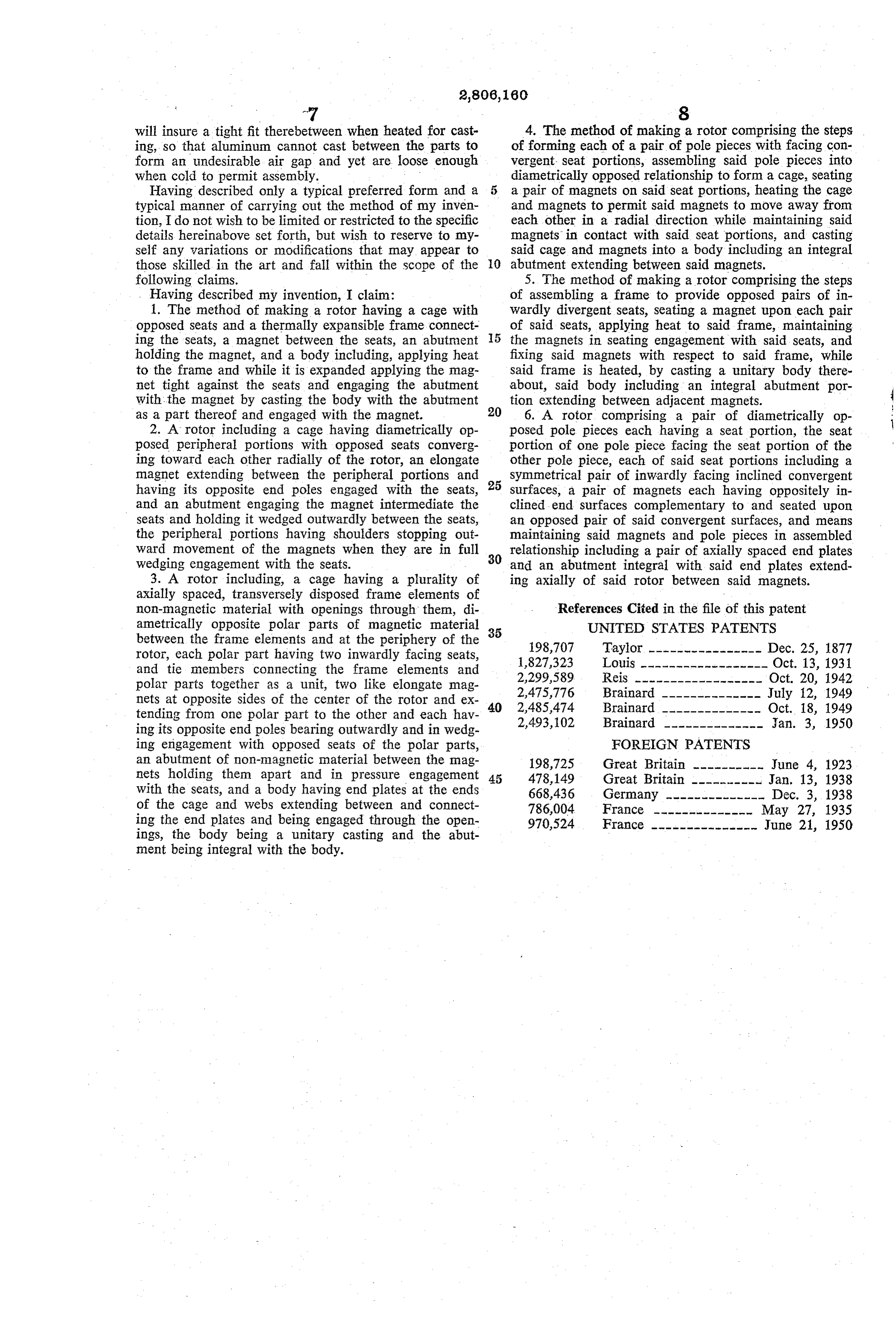
-7 8 will insure a tight fit therebetween when heated for cast 4. The method of making a rotor comprising the steps ing, so that aluminum cannot cast between the parts to of forming each of a pair of pole pieces with facing con form an undesirable air gap and yet are loose enough vergent seat portions, assembling said pole pieces into when cold to permit assembly. diametrically opposed relationship to form a cage, seating Having described only a typical preferred form and a a pair of magnets on said seat portions, heating the cage typical manner of carrying out the method of my inven and magnets to permit said magnets to move away from tion, I do not wish to be limited or restricted to the specific each other in a radial direction while maintaining said details hereinabove set forth, but wish to reserve to my magnets in contact with said seat portions, and casting self any variations or modifications that may appear to said cage and magnets into a body including an integral those skilled in the art and fall within the scope of the O abutment extending between said magnets. following claims. 5. The method of making a rotor comprising the steps . Having described my invention, I claim: of assembling a frame to provide opposed pairs of in 1. The method of making a rotor having a cage with Wardly divergent seats, seating a magnet upon each pair opposed seats and a thermally expansible frame connect of said seats, applying heat to said frame, maintaining ing the seats, a magnet between the seats, an abutment 5 the magnets in seating engagement with said seats, and holding the magnet, and a body including, applying heat fixing said magnets with respect to said frame, while to the frame and while it is expanded applying the mag Said frame is heated, by casting a unitary body there net tight against the seats and engaging the abutment about, said body including an integral abutment por with the magnet by casting the body with the abutment tion extending between adjacent magnets. as a part thereof and engaged with the magnet. 6. A rotor comprising a pair of diametrically op 2. A rotor including a cage having diametrically op posed pole pieces each having a seat portion, the seat posed peripheral portions with opposed seats converg portion of one pole piece facing the seat portion of the ing toward each other radially of the rotor, an elongate other pole piece, each of said seat portions including a magnet extending between the peripheral portions and Symmetrical pair of inwardly facing inclined convergent having its opposite end poles engaged with the seats, 25 Surfaces, a pair of magnets each having oppositely in and an abutment engaging the magnet intermediate the clined end surfaces complementary to and seated upon seats and holding it wedged outwardly between the seats, an opposed pair of said convergent surfaces, and means the peripheral portions having shoulders stopping out maintaining said magnets and pole pieces in assembled Ward movement of the magnets when they are in full 30 relationship including a pair of axially spaced end plates wedging engagement with the seats. and an abutment integral with said end plates extend 3. A rotor including, a cage having a plurality of ing axially of said rotor between said magnets. axially spaced, transversely disposed frame elements of non-magnetic material with openings through them, di References Cited in the file of this patent ametrically opposite polar parts of magnetic material 35 UNITED STATES PATENTS between the frame elements and at the periphery of the 198,707 Taylor ---------------- Dec. 25, 1877 rotor, each polar part having two inwardly facing seats, 1,827,323 Louis ------------------ Oct. 13, 1931 and tie members connecting the frame elements and 2,299,589 Reis ------------------ Oct. 20, 1942 polar parts together as a unit, two like elongate mag nets at opposite sides of the center of the rotor and ex 40 2,475,776
tending from one polar part to the other and each hav 2,493,102 Brainard -------------- Jan. 3, 1950 ing its opposite end poles bearing outwardly and in wedg ing engagement with opposed seats of the polar parts, FOREIGN PATENTS an abutment of non-magnetic material between the mag 198,725 Great Britain ---------- June 4, 1923 nets holding them apart and in pressure engagement 45 478,149 Great Britain ---------- Jan. 13, 1938 With the seats, and a body having end plates at the ends 668,436 Germany -------------- Dec. 3, 1938 of the cage and webs extending between and connect 786,004 France -------------- May 27, 1935 ing the end plates and being engaged through the open 970,524 France --------------- June 21, 1950 ings, the body being a unitary casting and the abut ment being integral with the body.
Provenance
- Collection
- Cited prior art
- Original PDF
- patentimages.storage.googleapis.com →
- Filed
- 1952-10-27
- Pages
- 6
- Method
- pdftotext (the PDF's own text layer) + pdftoppm 300dpi page scans
- Source
- Google Patents bibliographic record
- Granted
- 1957-09-10
- Inventors
- Maurice W Brainard; Keefe & Merritt Co O
- Transcribed from
- patentimages.storage.googleapis.com →