patent · US5663600
Variable speed wind turbine with radially oriented gear drive
2 September 1997
Page 1 — bibliographic record
United States Patent (19) 11 Patent Number: 5,663,600 Baek et al. 45) Date of Patent: Sep. 2, 1997 54 WARIABLE SPEED WINDTURBINE WITH McNearney et al., "The Effect of a Power Electronic Con RADALLY ORENTED GEAR DRIVE verter on Power Fluctuation and Harmonic Distortion in a WECS", pp. 237-241, ASME Wind Energy Symposium, 75) Inventors: Kwang Henry Baek; Joseph Philip Jan. 14-18, 1980.
Franz; John Peter Nadzam, all of Thomas, "An Integration Methodology for Large Wind-En Erie, Pa. ergy Conversion Systems". Final Report, Cornell Univer 73) Assignee: General Electric Company, Erie, Pa. sity. School of Electrical Engineering, Ithaca. NY. Jun. 1986. Brady, "Description and Test Results of a Variable Speed, (21) Appl. No.: 397,820 Constant Frequency Generating System". U.S. Department of Energy, Washington, DC. Dec. 1985.
22 Filed: Mar. 3, 1995 Herrera et al., "Experimental Investigation of a Variable (51) Int. Cl. .................. F03D 11/00; FO3D 1/00 Speed Constant Frequency Electric Generating System from 52 U.S. Cl. ............................................... 290/55; 290/44 a Ultility Perspective". Electrotek Concepts, Inc., Knoxville, 58 Field of Search .................... 290,44. 55; 416/132 B TN. May 1985.
"Options for Variable Speed Operation of Horizontal Axis 56) References Cited Wind Turbine Generators." U.S. Department of Energy,
2,441.446 5/1948 Schmitter ... ... 74,411 Primary Examiner-Steven L. Stephan 2,951,631 9/1960 Gregory . . 41.5/91 Assistant Examiner-Christopher Cuneo 4,140,433 2/1979 Eckel .......... 415/209.1 4,695,736 971987 Doman et al. ............................ 290/44 Attorney, Agent, or Firm-Marvin Snyder 4,757,211 7/1988 Kristensen ...... 290/55 57 ABSTRACT
5,083,039 1/1992 Richardson et al. A wind turbine assembly includes a gear drive assembly 5,155,375 10/1992 Holley ................ ... 29044 having an outer tubular member and an inner tubular 5,222,924 6/1993 Shin et al. .. 475/329 5,225,712 7/1993 Erdman ... ... 290/44 member, the inner member being positioned coaxially 5,289,041 2/1994 Lis .......... ... 29044 within the outer member. A pair of spaced bearings circum 5,289,042 2/1994 Holley ...................................... 290/55 scribe the inner tubular member and support the outer
OTHER PUBLICATIONS
member for rotation about the inner member. Propeller blades are coupled to the outer member for effecting rotation
Schmidt et al., "Evaluating Variable Speed Generating Sys in response to wind. An electric power generator mounted to tems on the DOE/NASA/MOD-O Wind Turbine', circ the inner member has a rotor shaft extending from one end. 1985, pp. 171-176. A gear unit is drivingly coupled between the rotor shaft and Boldin et al., "Induction Generators Adapted to Variable the outer member whereby rotation of the outer member is Speed Operated Wind Turbines". European Wind Energy effective to cause rotation of the rotor shaft at a velocity Conference, Oct. 22–26, 1984, Hamburg Frg, pp. 542-547. substantially greater than a rotational velocity of the outer Herrera et al., "Harmonics Generated by Two Variable member for generating electric power from the generator. Speed Wing Generating Systems", IEEE Transactions on
Energy Conversion, vol. 3. No. 2, Jun. 1988, pp. 267-273. 5 Claims, 3 Drawing Sheets
SS stSS,
asseX A arc Aldga
as DKNYS XP
Page 2
Drawing sheet — no readable text.
Page 3
Drawing sheet — no readable text.
Page 4
Drawing sheet — no readable text.
Page 5
WARABLE SPEED WIND TURBINE WITH alternating current electric power generator is coupled to the RADALLY ORENTED GEAR DRIVE flange end of the inner member and has a rotor shaft extending into a position proximal the end of the inner
BACKGROUND OF THE INVENTION member. Asunpinion gear is coupled to the rotor shaft at the end proximal the inner member and positioned to engage a
The present invention relates to wind turbines for opera plurality tion at variable speed under varying wind conditions, and, about theofsun planet gears, each of which is axially positioned pinion gear. Each of the planet gears is more particularly, to a combination wind turbine and AC mounted for rotation about its own axis on a corresponding power generator coupled to a radially oriented gear train. gear shaft, with each gear shaft being supported for rotation Wind turbines provide a method for extracting energy 10 on corresponding bearings. A pinion gear is attached to each from wind and converting the energy into electricity to be of the gear shafts for rotation with the gear shafts. A ring supplied either for individual use or into utility power grids. gear is formed on an inner surface of the outer member and The conversion of wind energy to electrical energy is is adapted to engage each of the pinion gears on the gear accomplished by coupling a turbine through appropriate shafts such that rotation of the outer member is effective to drive means to an electric power generator so that wind 15 rotatably drive each of the pinion gears and concurrently blowing onto the turbine will cause the rotor of the power drive each associated planet gear such that the sun pinion generator to rotate. Typically, the power generator is an gear is rotated in response to rotation of the outer member alternating current (AC) induction generator. The generator about the inner member. A plurality of propeller blades has stationary field windings which are coaxially wound coupled to the outer member extend radially outward for about a rotor that can be driven by the turbine on the wind 20 effecting rotation of the outer member in response to wind turbine. If the electrical power generated by the wind turbine impinging on the blades.
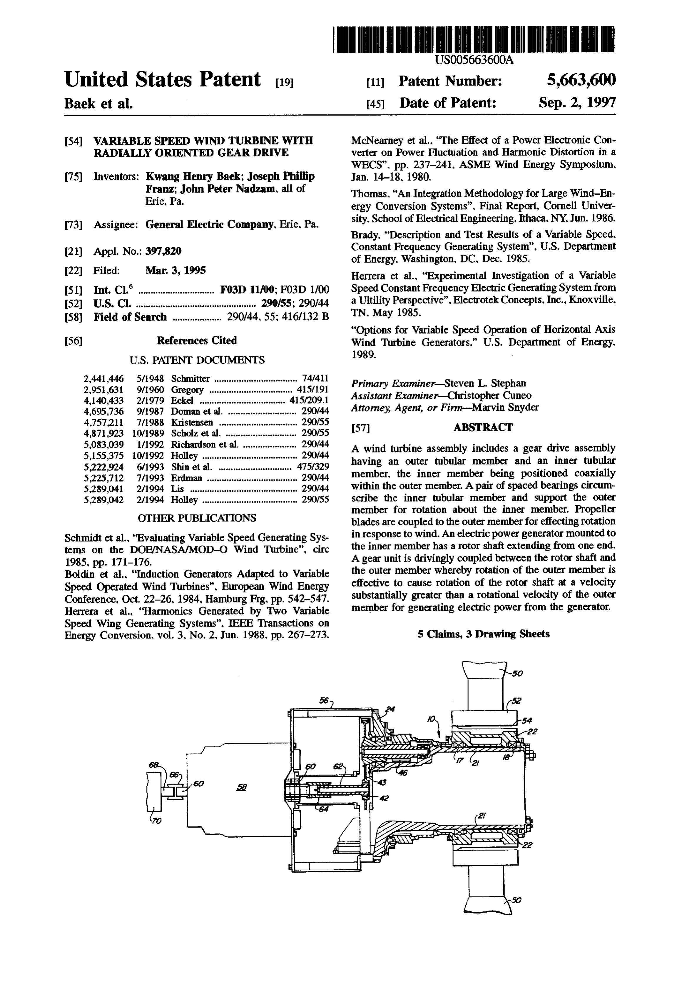
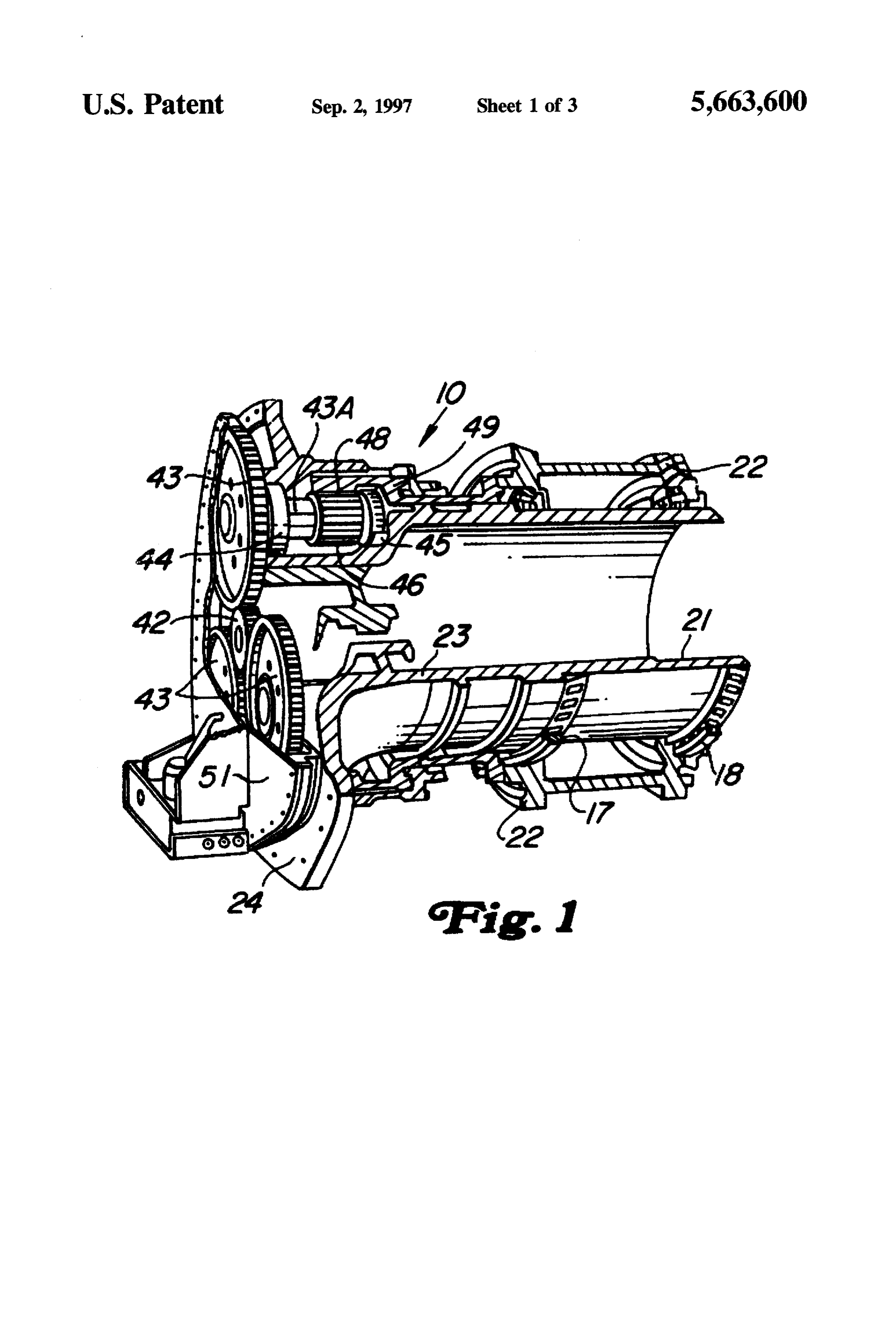
is to be supplied to a utility power grid, then it must have a constant frequency, such as 60 Hz, that is synchronized to BRIEF DESCRIPTION OF THE DRAWINGS the utility line frequency. Some wind turbines accomplish The features of the invention believed to be novel are set this function by operating at a constant speed. However, 25 forth in the appended claims. The invention, however, more efficient wind turbines operate at variable speed, together with further objects and advantages thereof, may causing the rotor of the AC generator to rotate at variable best be understood by reference to the following description speed, resulting in an AC power frequency that is variable. taken in conjunction with the accompanying drawing(s) in In such variable speed wind turbines, the AC power output which:
of the AC generator is rectified and then applied to an 30 FIG. 1 is a partial cross-sectional view of a radially inverter which converts the resultant DC power to AC power oriented gear drive assembly for use with the inventive wind at a controlled frequency. turbine;
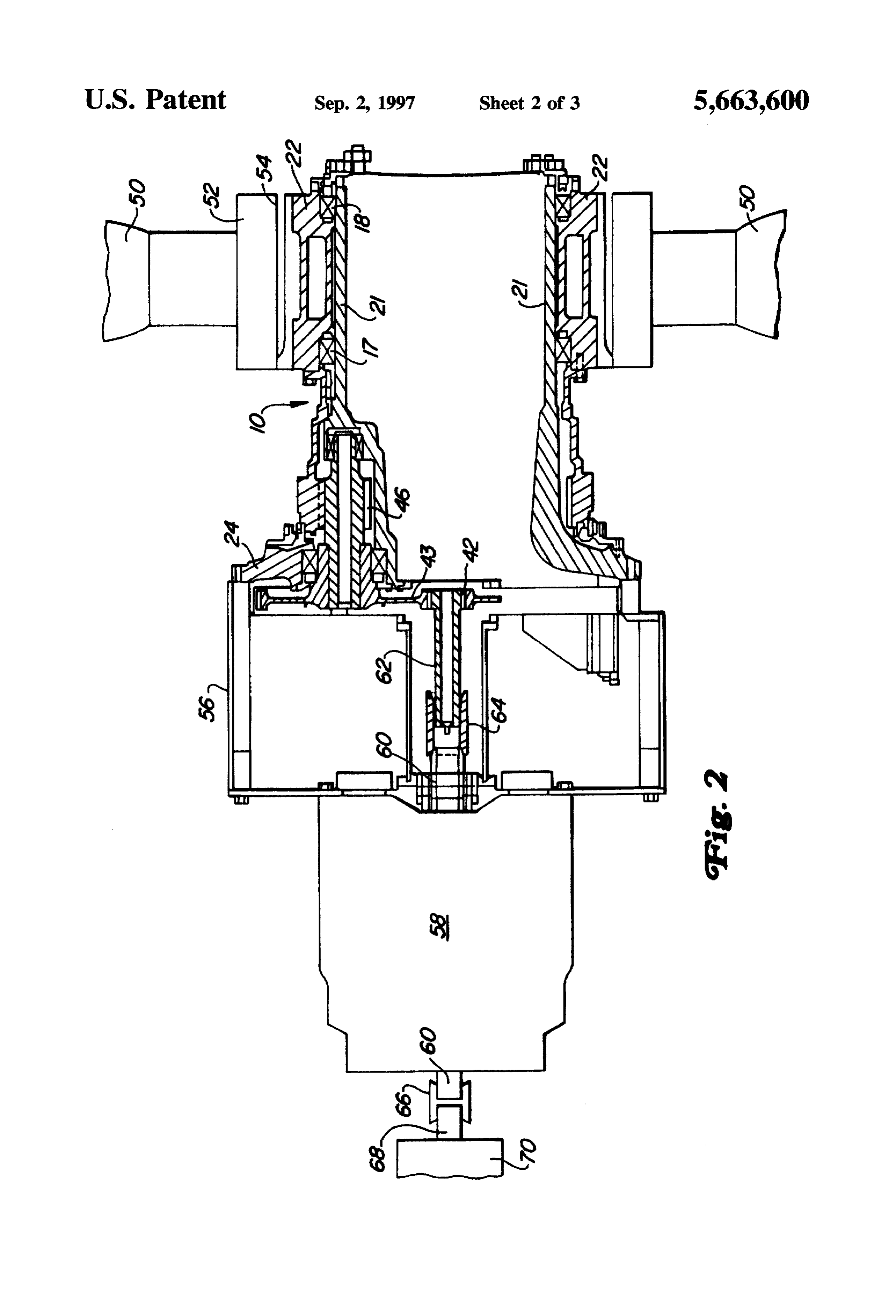
In conventional wind turbines, the components of the FIG. 2 is a simplified cross-sectional view of a wind power train connecting the turbine or turbine rotor blades to turbine in accordance with the present invention; and the AC generator rotor are laid out in a straight line. The 35 FIG. 3 is a cross-sectional view of an alternative form of result is an elongated turbine system which tends to require the wind turbine of FIG. 2.
excessive space, be relatively costly, inefficient in power DETALED DESCRIPTION OF THE conversion and sometimes unstable under various forms of dynamic loads from varying wind conditions. Such turbines INVENTION also may pose difficulty in maintenance due to the require Before turning to a description of the wind turbine ment for alignment of the axially laid-out elements of the assembly, reference is first made to FIG. 1 which illustrates turbine system. More particularly, when the major power one form of a radially-oriented gear train assembly for use train components such as the blade hub rotor, clutch, gear in the present invention. The gear train assembly 10 includes box, brake system and cooling system are laid out in a an inner hollow cylindrical member 21 and a concentric straight line, as is typical in the prior art, the design is 45 outer hollow cylindrical member 22. One end of inner elongated and can be susceptible to rotor dynamic unbal member 21 is an integral part of a frame structure 23 having anced loading. a flange 24 which may be bolted or otherwise attached to a
SUMMARY OF THE INVENTION
stationary structure for supporting the inner member 21 in a cantilever fashion. Outer member 22 is rotatably supported
Among the several objects of the present invention may 50 on a pair of spaced apart, large annular bearing assemblies be noted the provision of a wind turbine system which 17 and 18, preferably comprising tapered roller bearings. At overcomes the above and other disadvantages of the prior the flanged end of inner member 21 is a sun pinion gear 42 art; the provision of a wind turbine system which eliminates which meshes with three surrounding planet gears 43. Each the elongated power train layout; and the provision of a planet gear in turn is affixed to a corresponding shaft 43A power train for a wind turbine system which utilizes a 55 that is rotatably supported by a pair of spaced apart bearings three-dimensional arrangement by radial stacking of gear 44 and 45. Bearings 44 and 45 are mounted in the non train components. rotating frame structure 23 and each planet shaft has a pinion In an illustrative form, the invention comprises a variable gear 46 between these bearings. Each planet pinion gear 46 speed wind turbine having a radially oriented gear drive engages the teeth of an internal ring gear 48 on the inboard which includes an inner hollow cylindrical member and an end of a large diameter torque tube 49, whose other end is outer hollow cylindrical member, with the inner member bolted to outer member 22 for rotation therewith. The planet being nested generally concentrically within the outer mem and ring gears form a double reduction gear train, sometimes ber. An annular flange is attached to one end of the inner referred to as a "compound star" epicylic gear drive system, member and is adapted to support the inner member in a between sun pinion gear 42 and torque tube 49. A cover 51 stationary position. A pair of spaced-apart annular bearing 65 encloses the gear train, which is immersed in oil. assemblies circumscribe the inner member and support the The sun pinion gear 42 has a hollow center for receiving outer member for rotation about the inner member. An a rotor shaft. As will be described with regard to FIGS. 2 and
Page 6
3, the rotor shaft may extend from an AC generator, so that shown in FIG.2 except that shaft 62 now is inserted into the rotation of sun pinion gear 42 will effect rotation of the sun pinion gear from the opposite side. generator rotor. In the gear train of FIG. 1, as outer member While only certain preferred features of the invention 22 is rotated by external means such as, for example, turbine have been illustrated and described, many modifications and blades attached to outer member 22, member 22, being changes will occur to those skilled in the art. It is, therefore, connected to torque tube 49, will cause torque tube 49 to to be understood that the appended claims are intended to rotate about inner member 21. As torque tube 49 rotates, cover all such modifications and changes as fall within the internal ring gear 48 engages planet pinion gears 46, effect true spirit of the invention.
ing rotation of the shafts associated therewith and driving What is claimed is:
planet gears 43. The planet gears in turn drive sun pinion O 1. A variable speed wind turbine having a radially gear 42. The gear train or transmission illustrated in FIG. 1 oriented gear drive comprising:
thus utilizes a planetary gear system to provide high gear an inner hollow cylindrical member and an outer hollow train efficiency in a minimum space. The large bearing and cylindrical member, said inner member nested gener wheel diameters provide large load capacity and dynamic ally concentrically within said outer member and hav stability for external and internal loads. For example, inner 15 ing two ends;
member 21 typically has a relatively large inside diameter of about three feet. The gear train arrangement of FIG. 1 also an annular flange attached to one end of the inner member reduces the axial length of the design envelope and mini and adapted to support said inner member in a station mizes the number of flange joints, couplings and clutches ary position;
needed to construct a conventional gear train. a pair of spaced-apart. annular bearing assemblies cir FIG. 2, illustrates one example of a wind turbine incor cumscribing said inner member and supporting said porating the transmission or gear train of FIG. I. In this outer member for rotation about said inner member; embodiment, a plurality of propeller blades 50, each an alternating current electric power generator coupled to attached to a corresponding blade pitch change mechanism said one end of said inner member and having a rotor 52, are assembled on a blade hub assembly 54 which can be 25 shaft portion extending from one side of said generator attached to outer cylindrical member 22. A support frame 56 into a position proximal said one end of said inner is attached to flange 24 and supports an electric alternating member;
current generator 58 mechanically attached to gear train a sun pinion gear coupled to said rotor shaft portion at an assembly 10. Generator 58 includes a rotor (not shown) end thereof proximal said one end of said inner mem having a shaft 60 extending through a support 56. More 30 ber;
particularly, shaft 60 is coupled to a secondary shaft 62 a plurality of planet gears positioned in engagement with axially aligned with shaft 60. Sun pinion gear 42 is formed said sun pinion gear, each of said planet gears being integrally on one end of shaft 62 in a position to engage mounted on a corresponding gear shaft with each gear planet gears 43. Shaft 60 is connected to intermediate shaft 35 shaft being supported for rotation on corresponding 62 through a mechanical coupling 64. Coupling 64 may have bearing means;
internal splines and be press fitted onto generator shaft 60, a pinion gear attached to each said gear shaft for rotation but is preferably pinned or otherwise locked to shaft 62 by therewith;
means allowing a small amount of off-axis motion of shaft a ring gear formed on an inner surface of said outer 62 so as to prevent bending at the interface between gear 42 member and adapted to engage said pinion gear and gears 43. Coupling 64 also allows AC generator 58 to be whereby rotation of said outer member is effective to removed from the wind turbine assembly in the case of a rotatably drive said pinion gear to concurrently drive failure of the generator. In a preferred form, AC generator 58 each associated planet gear to drive said sun pinion may comprise a conventional AC motor in which driving of gear in a manner that effects rotation of said rotor shaft shaft 60 allows the motor to be operated in a generating portion; and mode. As will be apparent, a relatively slow rotation of 45 a plurality of propeller blades coupled to and extending propeller blades 50 on outer member 22 effects relatively radially outward of said outer member for effecting high speed rotation of rotor shaft 60 by virtue of the gear rotation of said outer member in response to wind ratio between pinion gears 46, planet gears 43 and sun impinging on said blades. pinion gear 42. 2. The wind turbine of claim 1 wherein said generator is Shaft 60 of motor 58 extends through the motor and an 50 mounted within said inner member.
opposite end is attached, via another coupling 66, to a 3. The wind turbine of claim 1 wherein said generator is second shaft extension 68. Shaft extension 68 may be used mechanically coupled to said one end of said inner member to support a braking system (not shown) contained within a and extends coaxially therefrom.
housing 70. 55 4. The wind turbine of claim 1 wherein said generator FIG. 3 shows an alternative embodiment of the wind comprises an alternating current electric motor. turbine system of FIG. 2 in which AC generator 58 is 5. The wind turbine of claim 1 and including mounting mounted inside inner cylindrical hollow member 21 and means attached to said inner member for supporting each affixed thereto. This arrangement goes even further in reduc said pinion gear in an axially stationary position with ing overall length of the wind turbine assembly by utilizing 60 respect to said inner member.
the space within inner member 21. The connection between motor 58 and sun pinion gear 42 is essentially the same as : it :: k sk
Provenance
- Collection
- Cited prior art
- Original PDF
- patentimages.storage.googleapis.com →
- Filed
- 1995-03-03
- Pages
- 6
- Method
- pdftotext (the PDF's own text layer) + pdftoppm 300dpi page scans
- Source
- Google Patents bibliographic record
- Granted
- 1997-09-02
- Inventors
- Kwang Henry Baek; Joseph Phillip Franz; John Peter Nadzam; General Electric Co
- Transcribed from
- patentimages.storage.googleapis.com →