patent · US4490093
Windpower system
25 December 1984
Page 1 — bibliographic record
United States Patent (19) 11) Patent Number: 4,490,093 Chertok et al. 45) Date of Patent: Dec. 25, 1984
54) WINDPOWER SYSTEM
FOREIGN PATENT DOCUMENTS
75 Inventors: Allan Chertok; John Gjertsen, Sr., 743890 1/1944 Fed. Rep. of Germany ... 416/44 A both of Bedford; Louis Manfredi, 1065339 9/1959 Fed. Rep. of Germany ... 416/52 Watertown, all of Mass. 908631 4/1946 France................................... 416/11 937903 8/1948 France .... ... 46/43. A 73) Assignee: U.S. Windpower, Inc., Burlington, 780.42 11/1980 U.S.S.R. ................................ 416/32 Mass. Primary Examiner-Everette A. Powell, Jr.
Attorney, Agent, or Firm-Cesari and McKenna 21) Appl. No.: 282,965 57 ABSTRACT 22) Filed: Jul. 13, 1981 A windpower system includes a support and a turbine having a shaft rotatively mounted to the support. The 51) Int. Cl. ................................................ F03D 7/04 turbine has variable pitch blades whose pitch is con 52) U.S. Cl. ........................................ 416/26; 416/32; trolled by the differential motion of a rotary control 416/41; 416/152; 416/165 shaft coaxial with the turbine shaft and the turbine shaft 58) Field of Search .............. 416/11, 41 A, 43, 43 A, itself so that the blade pitch can be varied by a station 416/44 A, 51A, 52A, 152, 31, 32, 151, 165, 26 ary motor without requiring any slip rings or other such wear-prone couplings. In the event of a power failure, 56) References Cited rotary motion of the control shaft is prevented so that
developed by the rotating turbine. Also, if the turbine is 1,929,436 10/1933 McCollough . ... 416/15 used to generate electrical power, an induction genera 2,480,468 - 8/1949 Hoinville ............................. 416/151 tor coupled to the turbine shaft is employed whose shaft 2,738,045 3/1956 Mergen et al. ... 416/51 X speed is indicative of generator output power. Accord 2,860,714 i/1958 DeMuth. ................................ 416/43 ingly, generator speed is monitored and used to control 4,006,925 2/1977 Scherer ...... 416/44 AX 4,047,842 9/1977 Avena et al. ........................ 416/152 the pitch of the turbine blades so as to maintain genera 4,066,911 1/1978. Sarchet. .......... ... 416/1.32 B X tor output power at the maximum value when wind 4, 193,005 3/1980 Kos et al.... ... 416/43 A X speed is below the machine's rated wind speed, and no 4,310,284 1/1982 Randolph........................ 416/32 B more than rated output power when wind speed ex 4,348,154 9/1982 Ducker .................................. 416/43 ceeds rated wind speed.
4,364,708 12/1982 David .............................. 46/132 B 4,366,387 12/1982 Carter et al................. 416/1.32 B X 5 Claims, 6 Drawing Figures
CONTROL
SATION
Page 2
Drawing sheet — no readable text.
Page 3
Drawing sheet — no readable text.
Page 4
Drawing sheet — no readable text.
Page 5
rosion, wear and contamination by dirt and moisture. In wINDPoweR SYSTEM short, then, the prior systems are not as simple and trouble-free as they might be. Also some of them do not
This invention relates to a windpower system or wind maintain adequate control over the turbine during un turbine and more particularly to apparatus for control usual circumstances such as the occurrence of sudden ling the pitch of variable pitch turbine blades in such a strong winds which subject the components of the sys system in response to wind speed changes. The present ten to unusually high mechanical stress. windpower system is especially useful for generating Also, in wind turbines such as this, it is essential that electrical energy. An overview of windpower systems the pitch control mechanism be designed such that used for such a purpose is contained in an article by E. O anticipated modes of failure drive the blades to their Henson, entitled "Electrical Energy from the Wind.” feather position at which they produce little or no found in the Energy Technology Handbook at 6-142 et torque so the turbine stops. For that purpose, prior seq (1977). apparatus rely on spring forces, complex battery-pow
BACKGROUND OF THE INVENTION
ered motor systems, or the self-feathering aerodynamic 15 properties of the turbine itself. In some circumstances,
There are, in present day use, numerous different such as where the blades or the pitch control mecha types of windpower systems or wind turbines used to nism is seized or ice-locked, these forces may be insuffi generate electrical power. These systems usually in cient to feather the blades so that considerable damage clude a shaft-mounted turbine whose torque output is to the turbine may result.
used to drive an electrical generator. When wind condi 20 SUMMARY OF THE INVENTION tions are favorable, the electrical output from the gener ator is coupled into the electrical utilities' transmission Accordingly the present invention aims to provide an lines. On the other hand when the wind speed is too improved windpower system or wind turbine. low, the generator is isolated from those lines. In order Another object of the invention is to provide such a to operate the generator at its optimum speed for maxi 25 system which achieves unusually close control over the mum power output, the wind turbine must produce a pitch of the system's turbine blades in response to wind selected relatively constant torque despite changes in speed changes.
wind speed. This is accomplished in most systems by Another object is to provide such a system which in sensing the rotational speed of the turbine. To maintain conjunction with an electrical generator produces maxi constant output power then, the pitch of the turbine 30 mum electrical power output under a wide variety of blades is varied so that the blades intercept more or less different wind conditions.
of the moving air stream momentum thereby to regulate A further object of the invention is to provide a wind the torque output of the turbine and, as a result, its power system which shuts down rapidly in response to speed. excessive wind speed and other emergency situations. Prior windpower systems have employed pitch angle 35 A further object is to provide a wind turbine which control mechanisms which are either more complex or develops unusually large forces to feather the blades in less effective than that of this invention. Therefore, they an emergency in the event they have become seized or are unduly costly to manufacture and repair, or are less ice-bound.
effective in controlling the speed of the turbine. For Still another object of the invention is to provide a example, some conventional turbines employ hydraulic windpower system which can operate for a prolonged pistons to change the blade pitch, with the fluid flow in period without maintainance.
the pistons being controlled by a speed-controlling gov Yet another object of the invention is to provide a ernor. Examples of such arrangements are disclosed in system such as this which utilizes, to a large extent, U.S. Pat. No. 2,832,895 and on page 351 of Van Nos conventional off-the-shelf components so that the cost trand's Scientific Encyclopedia, Third Edition 1958. In 45 of the system is kept to a minimum. another system, described in U.S. Pat. No. 2,583,369, Another object of the invention is to provide a wind the turbine hub is slidably mounted on its shaft. The power system whose individual parts can be repaired or turbine blades are terminated inside the hub by cams replaced relatively easily in a minimum amount of time. which slide in slots on that shaft. Also, springs bias the Other objects will, in part, be obvious and will, in hub to a reference position on the shaft. As the wind 50 part, appear hereinafter.
exerts pressure on the blades, the hub slides in one direc The invention accordingly comprises the features of tion or the other on its shaft so that the blades are construction, combination of elements and arrangement cammed to the proper pitch. of parts which will be exemplified in the following Still another rather complex pitch control mechanism detailed description, and the scope of the invention will is disclosed in U.S. Pat. No. 2,360,792. That mechanism 55 be indicated in the claims.
includes a hydraulic actuator and hydraulic compen Briefly, the present windpower system is designed to Sated governor. The actuator's piston is connected to be pivotally mounted atop a high tower so that it can the turbine blades and the movement of the piston swivel or yaw with the result that the turbine blades changes the blade pitch. In response to wind speed always intercept the wind stream. Usually the wind changes, the hydraulic governor delivers fluid under power system or turbine is one of many situated on a pressure to the actuator to cause the blades to assume "farm' with the electrical outputs of all of the systems their proper pitch. being coupled into the power grid of a nearby electrical Other prior windpower systems utilize various elec utility. Each system provides an electrical output to the trical components to control blade pitch, examples of utility as long as the prevailing wind speed exceeds a same being described in U.S. Pat. Nos. 3,974,395; 65 minimum value. When the wind speed drops below that 4,095,120 and 4,160,170. However those arrangements value, no useful power output can be developed by the require slip rings and other sliding electrical contact turbine and, therefore, the system is decoupled from the elements which are prone to failure due to surface cor power grid.
Page 6
Each system comprises a tubular turbine shaft which initiating turbine rotation, and when the blades are at a is rotatably mounted on a frame support. A turbine is so-called scram angle. This angle depends upon the connected to the end of that shaft. When the turbine is mechanical limits of the turbine. More particularly, rotated by air currents, the torque on that shaft is cou each turbine has a maximum safe wind speed at which it pled, via a speed increasing transmission, to the shaft of 5 can operate at full power. Operation of the turbine an electrical generator mounted to the support, causing above that point jeopardizes the fatigue life of the the generator to develop electric power for delivery to blades, tower and other mechanical components of the the utility. turbine. Thus if the turbine is operating at its maximum The system employs variable pitch turbine blades rated speed and the blades have had to be feathered whose pitch angle can be varied to facilitate turbine 10 back as far as the scram angle (e.g. 20), this indicates a start-up and shut-down, and to limit turbine torque wind speed unsafe for continued operation of the tur output when wind speed exceeds that necessary to pro bine. In this situation, the controller responds to a signal duce rated power from the generator. For this, the from the pitch sensor and activates the servomotor so rotary motion of the turbine shaft is also coupled by a that the control shaft is rotated much slower than, or clutch to a coaxially-mounted, tubular, control shaft. 15 even in the opposite direction from, the turbine shaft. The control shaft is internally threaded to accept a Resultantly, the blades are moved to their feathered threaded pitch actuating rod, which extends from the position quite rapidly and the turbine halts. control shaft into the turbine hub. There, it is connected The present system also includes provision for stop to the blades by bell cranks so that linear movements of ping the turbine in the event of a power failure to the the actuating rod result in changes in the pitch angle of 20 system or under other emergency conditions such as a the turbine blades. The same linkages in the hub also failure of pitch servo motor. For this purpose, the sys rotatively connect the actuating rod to the turbine shaft term employs an electrical brake acting between the so that those two elements rotate in unison. control shaft and the support. During normal operation The system further includes a reversible servomotor of the turbine, electrical power to the brake, derived for rotating the control shaft thereby to adjust the rela 25 from the network which also tools the generator, disen tive speed of the control and turbine shafts. When the gages the brake, so that the control shaft is free to rotate turbine blades are oriented at the correct pitch for the relative to the support. However, if when the turbine is prevailing wind speed, the system controller engages operating, the connection to the power network should the clutch, thereby rotatively coupling the control shaft be interrupted so that blade pitch is no longer under. to the turbine shaft so that those shafts, as well as the 30 control, not only is the clutch disengaged, but the de actuating rod, rotate in unison. Consequently, there is energized brake engages and couples the control shaft no linear movement of the actuating rod as would directly to the support. Since the turbine continues to change the pitch of the turbine blades. turn, the actuating rod is advanced so that the blades are: However, if the wind speed changes, the system's brought to their fully feathered position thereby halting controller disengages the clutch and drives the servo 35 the turbine. Failsafe feathering, when power is inter motor so as to rotate the control shaft either faster or rupted, is vital because under such a condition, the slower than the turbine shaft, thereby to cause the actu generator will be unloaded and the sudden loss of tor ating rod to advance or retract by the necessary amount sional load on the turbine will cause it to rapidly accel to adjust the pitch angle of the blades for that different erate to a destructive overspeed condition if no feather wind speed. Thus, in a particular embodiment, if the ing action is taken. --- - :- - - wind speed decreases, the motor rotates the control The same emergency braking action occurs if the shaft faster than the turbine shaft so as to retract the blades do not assume a certain pitch angle after they are actuating rod and move the blade pitch angle toward directed to do so by the controller. For example, if the full-power position (i.e. a pitch angle of approxi under unsafe wind conditions, the blades reach the mately 0), with the result that the turbine develops 45 scram angle, yet fail to feather within a short time inter more torque and speeds up. Conversely, if the wind val because of a malfunction of the servomotor, the speed increases, the motor rotates the control shaft controller de-energizes the brake thereby simulating a slower than the turbine shaft. This causes the actuating power failure. The brake thereupon couples the control rod to advance and thereby move the pitch angle of the shaft to the support so that the blades are again driven blades toward the feather position (i.e. a pitch angle of 50 to the feathered position. Thus the brake serves as a 90), with the result that the turbine produces less back-up for the servomotor in a scram situation. It is torque and slows down. Thus, the linear or axial posi important to appreciate that in this failsafe mode of tion of the actuating rod provides a direct indication of operation, the blades are feathered solely due to the the blade pitch and thus wind speed. - motion of the wind-driven turbine relative to the braked It is important to note that through the use of the 55 control shaft. Since the moving turbine possesses a con aforesaid coaxial differential shaft arrangement, the siderable amount of torque, it can apply considerable system is able to transfer control forces to the rotating force to drive the blades to the safe feathered position in turbine blades from a fixed rotary servomotor without the event they are ice-bound or the pitch control mech the need for rotary electrical or hydraulic couplings, anism has seized.
swivel joints, swash plates, or other such wear-prone 60 Furthermore, in the present system as soon as the parts as are found on conventional wind turbines. blades are feathered, the actuating rod, mechanically A blade pitch sensor responds to the linear position of disengages the brake so that the control shaft is decou the actuating rod and applies signals to the controller pled from the support, while at the same time the rod is which indicate when the blades are feathered and, when coupled to the control shaft. Now, the control shaft, they are at the full-power position. The sensor also 65 actuating rod, and turbine shaft all rotate in unison so signals the controller when the blades are at the so that there can be no linear movement of the actuating called start position (i.e. a pitch angle of approximately rod and, thus, no movement of the blades from the 45) which is the optimum position of the blades for feathered position.
Page 7
In a system such as this, it is, of course, desirable to the system can be kept to a minimum. Furthermore, operate the generator so that it produces maximum repairs, when needed, can be made relatively quickly so output power. On the other hand, it is essential that the that the downtime of the system is also a minimum. system including blades, transmission, generator, and Finally, because of its mode of achieving blade pitch tower not be stressed beyond their mechanical or ther control, the system responds quickly and reliably to mal limits. To satisfy these constraints, the system moni rapid wind speed changes and is fully protected in the tors the output power from the generator and varies the event of excessive wind speeds or emergencies that pitch of the blades to limit generator output to its maxi might cause thermal or mechanical damage to the sys mum power rating. Instead of measuring the generator tel.
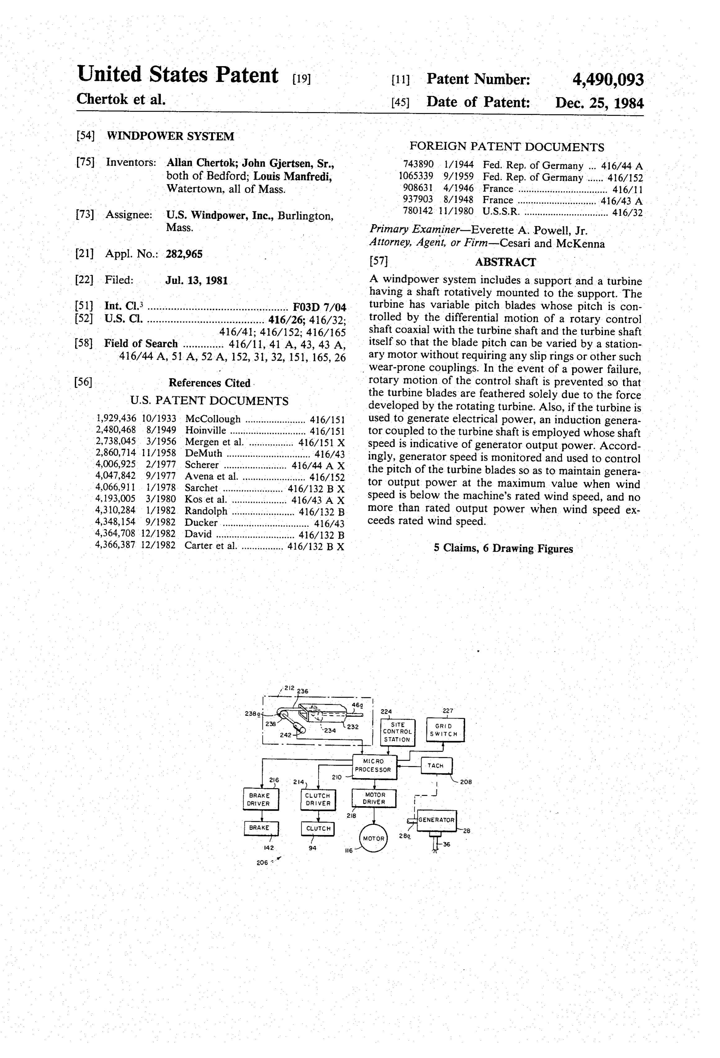
output directly, however, the system employs a genera O BRIEF DESCRIPTION OF THE DRAWINGS tor of the induction type which operates normally at a speed somewhat greater than its nominal synchronous For a fuller understanding of the nature and objects speed. The deviation from synchronous speed is re of the invention, reference should be had to the follow ferred to as "slip” given in absolute RPM or as a frac ing detailed description, taken in connection with the tion or percentage of synchronous speed. It is charac 15 accompanying drawings, in which:
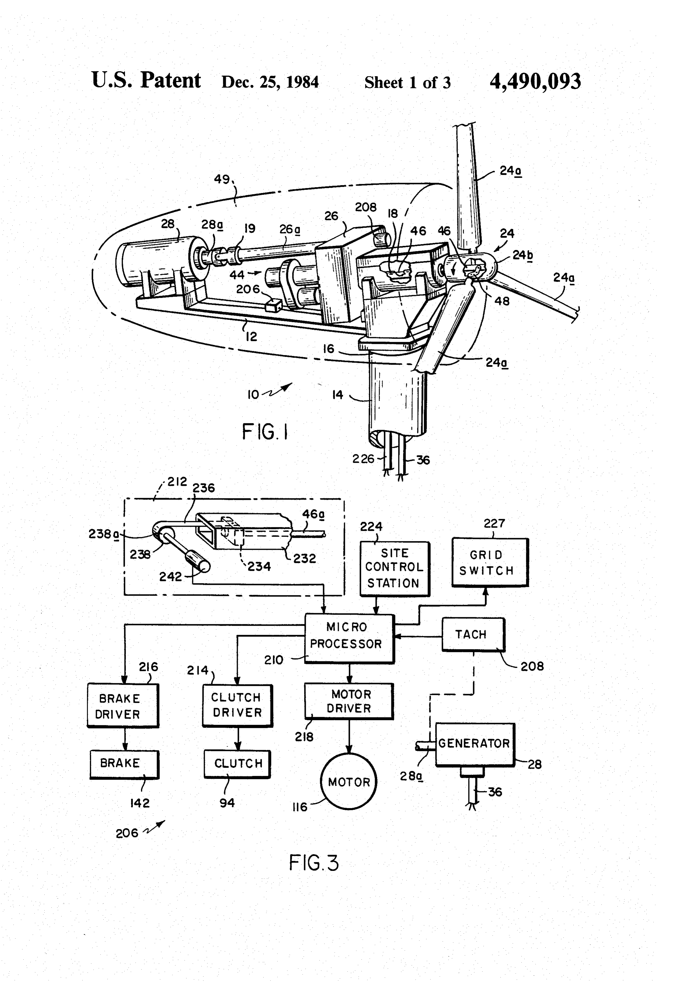
teristic of such a generator that its output power varies FIG. 1 is a fragmentary perspective view with parts directly with the amount of slip. Therefore, the shaft broken away of a tower-mounted windpower system speed of the generator which changes with slip, pro incorporating the invention;
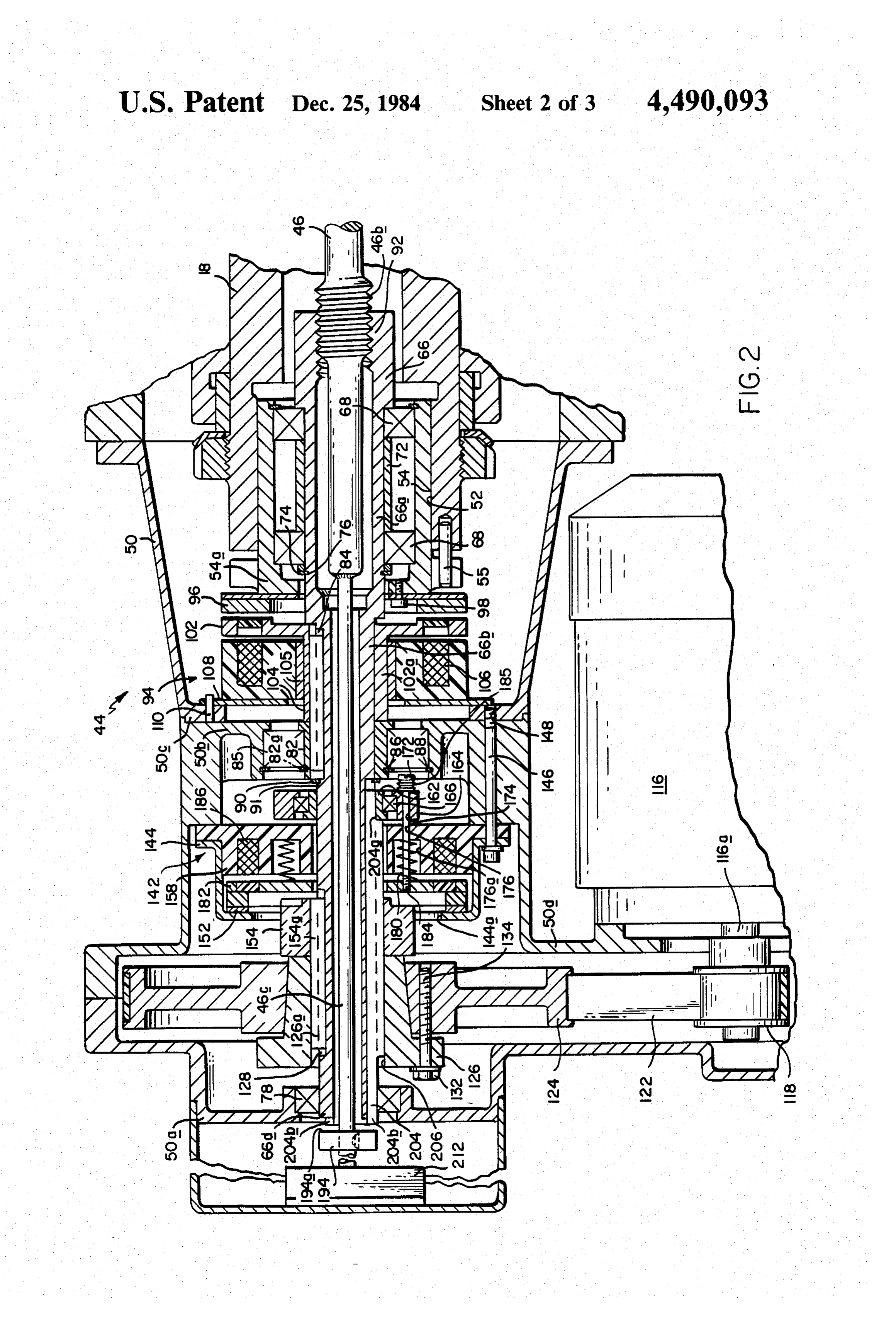
vides a direct indication of the generator output. A FIG. 2 is a sectional view on a larger scale showing tachometer monitors that speed and applies a signal to 20 the FIG. 1 system in greater detail; the controller. The controller, in turn, controls the FIG. 3 is a schematic diagram showing the control clutch and the servomotor so as to vary the pitch of the section of the FIG. 1 system;
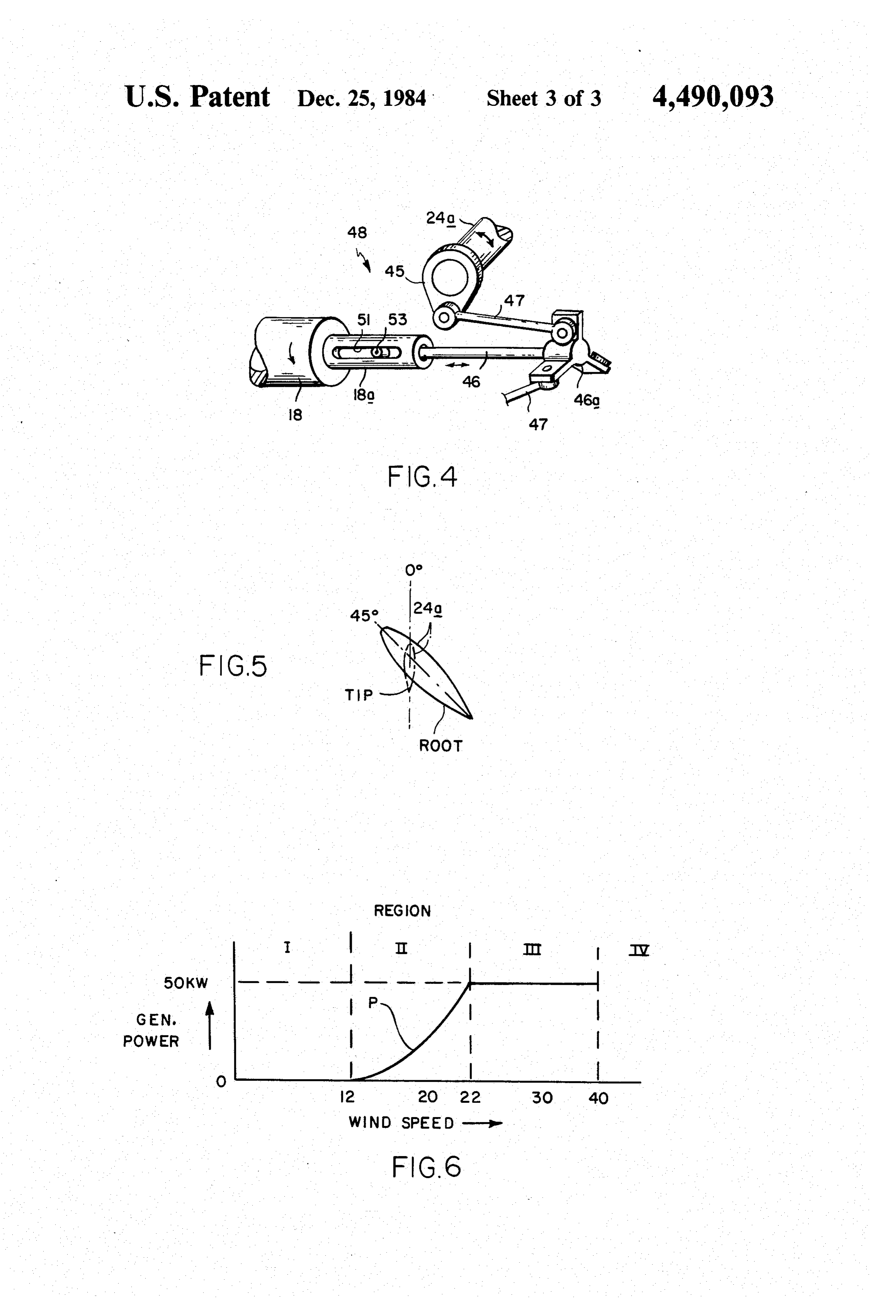
turbine blades from their aforesaid maximum power FIG. 4 is a schematic diagram showing the system's position as needed to limit output power from the gen blade pitch control linkage in greater detail; erator to its maximum rating despite changing wind 25 FIG. 5 is a schematic diagram illustrating the profile conditions. of each blade of the system; and When the present system is started, we will assume FIG. 6 is a graphical diagram illustrating the opera the blades are feathered and the turbine is stationary. A tion of the FIG. 1 system.
signal from a central control station causes the control DESCRIPTION OF THE PREFERRED ler to decouple the clutch and drive the servomotor so 30 EMBODIMENT that the motor rotates the control shaft. This retracts the actuating rod thereby moving the blade pitch angle While the windpower system specifically described toward the start position. When the pitch sensor detects herein is used to drive a generator to deliver electrical that the blades have reached start-up pitch, the control power to a utility network ("grid'), it should be under ler engages the clutch and stops the servomotor so that 35 stood that the same basic system can also be used as the the blades remain at this pitch angle. motive means for "stand alone' electric generators, If wind speed is above the minimum necessary to irrigation pumps, compressors, conveyors, etc. sustain useful power output from the turbine, the tur Referring now to FIG. 1, the windpower system or bine will be accelerated to a start-up speed. If this speed wind turbine shown generally at 10 comprises a frame is sustained for a brief period, the controller will again support 12 secured to the top of a tower 14 by way of a disengage the clutch and activate the servomotor to rotary mounting 16 which permits the support to swivel move the turbine blades to their full-power position. or yaw. The tower 14 is typically 50 to 150 feet high When the generator tachometer indicates a speed-pro depending upon the prevailing winds at the particular ducing positive slip so that the generator is producing site. The system includes a rotary turbine shaft 18 which useful power, the controller effects connection of the 45 is terminated by a turbine indicated generally at 24. The generator to the power grid. position and the turbine 24 relative to the rotary mount As the wind speed increases, the generator speed ing 16 is such that the support 12 swivels as needed to increases until the generator reaches the allowed maxi maintain the turbine downwind. If desired, a yaw con num power. At this point, the generator speed sensor trol (not shown) can be included which will positively issues a signal to the controller causing it to decouple 50 rotate the support through its mounting 16 so that as the the clutch and activate the servomotor to rotate the wind direction changes the turbine 24 is kept down control shaft relative to the turbine shaft to move the wind.
blade pitch toward feather. As a result, the turbine The illustrated turbine 24 is designed so that the inter slows down to maintain the generator at its maximum cepted air stream turns it in a selected direction, i.e. power output condition. Conversely, a subsequent de 55 counterclockwise as viewed in FIG. 1. Torque is taken crease in wind speed causes the controller to move the from the shaft 18 by way of a transmission indicated blade pitch toward the full-power position to maintain generally at 26. Since the illustrated windpower system the generator at maximum power. is used to generate electricity, the transmission output If the wind speed should increase to the point where shaft 26a is coupled via a universal coupling 19 to the the pitch of the blades has to be moved to the scram shaft 28a of a generator 28 to run the generator at high angle in order to maintain the generator at its rated speed.
output, indicating excessive strong winds, the controller Thus, when the turbine 24 turns, the generator 28 disengages the clutch and activates the servomotor so as produces an electrical output which is conducted from to move the blades to feather thereby stopping the tur the system by way of a cable 36 extending through bine. 65 tower 14 to the electrical load. In most applications, the Since the present system is composed primarily of electrical power is fed into the local utility grid. rugged mechanical parts, many of which are off-the In the illustrated system, the turbine blades 24a are shelf items, the cost of manufacturing and assembling rotatively mounted in the turbine hub 24b and provision
Page 8
is made for adjusting the pitch of these blades. More to the left of bushing 82 to fix the axial position of the particularly, a pitch control section indicated generally clutch 94 on the control shaft and to absorb thrust. at 44 is mounted to transmission 26. In response togen Referring to FIGS. 1 and 2, the pitch actuating rod 46 erator speed changes, the control section 44 moves an leading from the turbine 24 extends into control section, actuating rod 46 extending axially through shaft 18 5 44 and more specifically into the end of the tubular from that section to the turbine 24. control shaft 66. Furthermore, that end of rod 46 is Inside the hub 24b, the rod is connected by way of externally threaded at 46b to mesh with a nut 92 formed three bell cranks 48 to the inner ends of the blades 24a. at the end of control shaft 66. Also, as described above The bell crank 48 connection between rod 46 and one in connection with FIG. 4, rod 46 is constrained to such blade 24a is shown in detail in FIG. 4. As seen 10 rotate with the turbine shaft 18, yet is movable axially there, the inner end of blade 24a a carries an eccentric relative to that shaft by virtue of the pin-in-slot connec member 45. Also, a three-armed spider 46a is mounted tion between the rod and shaft. As noted previously, the to the end of rod 46. A link 47 is pivotally connected at lengthwise or axial movement of the pitch actuating rod its opposite ends to member 45 and an arm of the spider 46 changes the pitch of the turbine blades 24a in one so that linear movement of rod 46 in one direction or 15 direction or the other depending upon whether the the other rotates the blades 24a in one direction or the control shaft is rotated at a faster or slower rate than the other to change their pitch. Similar links 47 connect the turbine shaft 18.
other two arms of spider 46a to the remaining two tur For example, assuming shaft 18 is rotating in a coun bine blades 24a. In order to rotatively couple rod 46 to terclockwise direction as shown in FIG. 1 and the rod, the turbine shaft 18 while permitting axial movement of 20 thread 46b is a right hand thread, if shaft 66 is rotated at the rod relative to the shaft, a reduced diameter shaft the same speed as shaft 18, then no relative movement end segment 18a is formed with a lengthwise slot 51. occurs between the control shaft nut 92 and the Also, a pin or roller bearing 53 attached to rod 46 threaded end 46b of the actuating rod, since that rod. - projects into that slot, functioning more or less as a cam turns with shaft 18. Accordingly, there is no change in follower. 25 the pitch angle of the blades. On the other hand, if shaft As shown in FIG. 5, the blades 24a themselves are 66 is rotated counterclockwise, as viewed in FIG.1, at shaped as air foils. Furthermore, they have an apprecia a faster rate than shaft 18, the threaded engagement of ble twist from root to tip. Typically as shown in that the nut 92 with the rod end 46b, causes the rod to retract figure, the blade tip is oriented about 45 relative to the lengthwise into the shaft 66, i.e., toward the left in FIG. root of the blade. 30 2. This lengthwise movement of the rod 46, in turn, A streamlined ventilated housing or cowl shown in rotates the blades 24a so as to move them toward their dotted lines at 49 in FIG. 1 encloses the support 12 and full-power position. Conversely, if the shaft 66 is held other components of the system except, of course, the stationary or is rotated clockwise, as viewed in FIG. 1, turbine 24. then the relative rotary motion of the control rod, Refer now to FIG. 2 which shows the components of 35 threads 46b, with respect to the nut 92 will move the the pitch control section 44 in greater detail. The shaft control rod 46 out of the shaft 66 so that the turbine 18 projects into a housing 50, where it is formed with a blades are moved toward their feathered position. counterbore 52 in order to receive a flanged tubular In order to control the relative rotation of the control extension 54. The extension is rotatively coupled to the shaft and turbine shaft, the illustrated control section 44 shaft by pins 55 extending through the extension flange 40 includes a clutch shown generally at 94 which operates into the end of the shaft. Positioned coaxially within between the shaft 18 and the control shaft 66. The shaft 18 and its extension 54 is a tubular control shaft 66. clutch 94 includes a discoid clutch plate 96 secured by Shaft 66 has a reduced diameter segment 66a within threaded fasteners 98 to the inner end wall 54a of shaft extension 54 which forms a seat for a bearing unit 68 extension. 54. The plate 96 and its connection to exten located inside extension 54 at one end thereof. A second 45 sion 54 are such that the plate can flex axially to some bearing unit 68 spaced from the first by a tubular spacer extent. Disposed directly opposite plate 96 is a second 72 is located at the opposite end of extension 54. The clutch plate 102 having a tubular extension 102a en axial position of the shaft 66 relative to the bearing units gaged on the control shaft segment 66b. The plate ex and extension 54 is maintained by a locking ring 74 tension 102a has an internal key 104 which slidably which engages in a circumferential groove 76 formed in 50 engages in keyway 84 in that segment so that the plate shaft segment 66a beyond the bearing units 68. 102 rotates with the control shaft. Encircling the clutch The opposite end of shaft 66 is journaled by way of a plate extension on a sleeve bearing 105 is an electromag bearing unit 78 located in the end wall 50a of housing 50 netic toroidal wire coil and polepiece unit 106. A dis remote from the turbine. In the illustrated system, a coid plate 108 is attached to coil polepiece unit 106 and reduced diameter segment 66b of control shaft 66 ex-55 is restrained from rotation by pins 110 fitted to internal tends through an internal neck 50b formed in housing 12 flange 50c in housing 50. Plate 102 is normally disen intermediate the ends thereof. A bushing 82 is engaged on shaft segment 66b. The bushing has an internal key gaged from plate 96 so that shaft. 18 (and rod 46) rotates 82a which slidably engages in a longitudinal keyway 84 clutch coil andof polepiece independently control shaft 66. However, when the unit 106 is energized, the in the shaft segment so that the bushing is rotatively 60 clutch plate 96 is flexed axially into frictional engage locked to the shaft. The bushing 82 rotates relative to ment with plate 102 so that shafts 66 and 18 rotate in housing neck 50b by way of a bearing unit 85 which unison. As noted previously, as long as there is no rela seats against the bases of the bushing and neck. Locking tive movement between those two shafts, there is no rings 86 and 88 engage in circular grooves inscribed axial movement of pitch actuating rod 46 and, therefore, around the outside of bushing 82 and the inside of neck 65 no change in the pitch of the blades 24a. 50b so that the bushing is locked to the housing axially, but can rotate relative thereto. A third locking ring 90 theSuch relative movement is effected by disengaging clutch 94 and rotating the shaft 66 at a faster or seats in a groove formed in control shaft section 66b just slower rate than shaft 18. In the illustrated system, this
Page 9
is accomplished by means of a reversible servomotor bolts 172. These are substantially stiffer than springs 180 116 mounted to a radial enlargement 50d of housing 50. and are not materially compressed by the force required The shaft 116a of the motor carries a pulley 118 which translate collar 164 to close the gap between brake disk is connected by a belt 122 to a larger pulley 124 coupled 182 and plug 158. However, when this gap is closed, the to control shaft 66. More particularly, the pulley 124 is Belleville spring washers 185 allow collar 164 to be engaged on a tapered locking bushing 126 which encir translated by a small additional amount without apply cles shaft 66 just inboard of its bearing 78. The bushing ing destructive tensile loads on bolts 172. A wire coil has an internal key 126a which slidably engages in a 186 is contained in the plug 158 which, when energized, keyway 128 formed in shaft 66. Pulley 124 is secured to moves the plate 182 to its retracted position. Thus as the bushing by appropriate threaded fasteners 132 ex 10 long as the brake coil 186 is energized, the control shaft tending through openings in the bushing flange and 66 is free to rotate within the housing 50. However, turned down into threaded passages 134 in the pulley so whenever the brake coil is de-energized due to a power as to engage the pulley with the tapered bushing. As failure, the springs 180 press the plate against the brake will be described in detail later, the motor 116 is con shoe 152 which is secured by way of brake housing 144 nected in a servo loop which varies the speed of the 15 to the housing 50. Therefore, the control shaft 66 to motor as the wind speed changes. Therefore, the motor which the plate 182 is connected is rapidly brought to a rotates control shaft 66 relative to turbine shaft 18 (and stop. Note that in the event of such a power failure, the rod 46) to move the actuating rod 46 so as to feather the clutch 94 will be disengaged thereby decoupling the turbine blades when the wind speed exceeds that re control shaft nut 92 and control rod screw 46a so that quired to develop generator rated power and to move 20 shaft 66 is free to move independently of the turbine them toward their full-power position when the wind shaft 18.
speed falls below that which will sustain rated generator Assuming that the turbine shaft 18 and actuating rod output. 46 are rotating counterclockwise as indicated, their In the illustrated preferred embodiment of the sys rotary motion relative to the stopped shaft 66 causes the tem, provision is also made for fully feathering the tur 25 actuating rod 46 to move out of the control shaft, i.e. bine blades so as to stop the rotation of the turbine 24 toward the right in FIG. 2. This results in the blades 24a and its shaft 18 in the event of a power failure or any being brought to their feathered position so that the other failure which disables the servomotor 116. More chord surfaces of the blades 24a no longer intercept the particularly and referring to FIG. 2, a brake shown moving air stream. Accordingly, the turbine 24 slows generally at 142 is provided in section 44 which acts 30 down and eventually will come to a stop. It should be between the control shaft 66 and the housing 50 to bring appreciated, then, that, since the brake engages when the shaft 66 to a complete stop. With the shaft 66 de-energized, the control section 44 operates in a fail stopped, the continued rotation of the shaft 18 and the safe mode in that, in the event of a power failure, the pitch actuating rod 46 to which it is linked causes the brake 142 always operates to stop the turbine 24. rod 46 to move out of the control shaft nut 92 so as to 35 When the blades 24a are brought to their fully feath rotate the blades 24a to their feathered position. As they ered position, the turbine 24 may still be rotating due to approach that position, the blades gather less wind and, its inertia. Means to disengage the brake must therefore accordingly, the turbine 24 gradually slows to a stop. be provided to prevent further advance of the blade The brake 142 comprises a flanged brake housing 144 beyond the feathered position which could destroy secured to the housing flange 50c by bolts 146 extending components of the pitch control mechanism. More par through the brake housing flange and turned down into ticularly and still referring to FIG. 2, actuating rod 46 threaded openings 148 in housing flange 50c. Inside the has an extension 46c which projects through the hous brake housing 44 is a discoid brake shoe 152 mounted to ing end wall 50a. Mounted to that extension is a collar a hub 154 which extends out through an opening 144a in 194. Also, the end 66d of the shaft 66 projects through the brake housing. Hub 154 has a key 154a which is 45 the same wall opposite the collar. The relative positions slidably engaged in the control shaft key way 128 so of the collar and the shaft are such that when the actuat that the hub and brake shoe rotate with that shaft. ing rod 46 advances to a position corresponding to the Also, positioned inside the brake housing 144 is a feathered position of the blades 24a, the brake 142 is discoid plug 158 which is spaced opposite the brake released mechanically. More particularly, a circular shoe 152. Beyond the plug is a bushing 162, slidably 50 array of three push rods or keys 204 are slidably posi mounted to shaft segment 66b. Also a ring or collar 164 tioned in longitudinal passages 206 in the wall of control is rotatively mounted to that bushing by way of a bear shaft section 66b. The inner ends 204a of the rods en ing unit 166. Bolts 172 are slidably received in openings gage the bushing 162. Their outer ends 204b project out 174 in collar 164. These bolts extend through registering beyond the shaft end 66d. The positions of the rod ends openings 176 in plug 158 which openings are counter 55 204b are such that at blade feather, the collar 194 en bored at 176a to accept compression springs 180. gages the rods which thereupon shift the bushing 162 Located between the brake shoe 152 and plug 158 is toward the right in FIG. 2 to disengage the plate 182 an annular plate or disk 182. A circular array of from the brake shoe 152.
threaded openings 184 are formed in plate 182 which As mentioned previously, Belleville spring washers openings are threaded to receive the bolts 172. Thus the 60 185, present under the heads of bolts 172, are substan plate is held by the bolts 172 in register with brake shoe tially stiffer than springs 180 and are therefore not mate 152. Furthermore, the plate is biased against the brake rially compressed by the actuating force applied to shoe by the springs 180. However, there is sufficient separate the braking surfaces of plate 182 and shoe 152. clearance between the engaging plate and the plug 158 Now while the brake can no longer retard the rota to permit the plate to be retracted against the plug, with 65 tion of the control shaft, the inertial and frictional the bolts 172 sliding in the plug openings 176 and the torque of the de-energized servomotor multiplied by collar openings 174 toward the right in FIG. 2. Belle the step-up ratio of the pulleys 118 and 124 can still ville spring washers 185 are included under the heads of retard rotation of that shaft. This would attempt to
Page 10
drive the mechanism further in the feather direction if ler 206, which monitors the speed of generator 28, turbine rotation has not ceased at this point. Such fur senses that the generator speed has exceeded a selected ther drive in the feather direction could damage pitch magnitude, e.g. 250 rpm for a certain time e.g. 30 sec control mechanism components. This possibility is pre onds, the controller causes the blades to be moved to cluded in the present arrangement, however, by further their full power position. That is, the controller disen displacement of protruding rods 204b permitted by the gages the clutch 94 and activates servomotor 116 until Belleville washers and the engagement of collar face the blades have moved to the full power angle, e.g. 194a and control shaft end 66d which clutchlike action, about 0, after which the motor is disabled and the rotatively couples the actuating rod and control shaft so clutch re-engaged to lock the blades at that angle. that no further relative motion of those parts is possible, 10 With the blades at the full-power position, as the whereupon the blades are effectively locked in the wind speed increases, the generator speed increases. feathered position. Resultantly, the generator output power increases as The objective of the present system is to operate the shown by the waveform P in the Region II in FIG. 6. wind turbine 24 as closely as possible to maximum effi When the generator reaches or exceeds synchronous ciency to obtain maximum output power from the gen 5 speed, the controller 110 closes switch 227 to connect erator 28, while protecting both the turbine and genera the generator 28 to the power grid.
tor from mechanical or thermal damage. For this pur On the other hand, if that start-up speed is reached pose, then, the control section 44 includes an electronic only momentarily due to a stray wind gust, the blades controller shown generally at 206 in FIGS. 1 and 3. The remain at their start angle and the turbine simply idles in controller monitors the generator output and responds 20 operating Region I with the generator isolated from the to changes in wind speed so as to control the pitch of utility grid. -- the turbine blades. When wind speed is less or equal to In a typical installation, the maximum power level is that which will sustain rated generator power output, reached at a "rated' wind speed of approximately 22 near-optimal power output is provided by holding the mph. When the generator speed reaches the speed for blades at their full-power pitch position and no servo 25 maximum power, this condition is sensed by tachometer action is required. However, when wind speed exceeds 208 and the processor 210 with which it communicates. that required for rated output, the blades are moved In response to this condition, the processor momen toward the feathered position so as to limit generator tarily decouples the clutch94 and energizes servomotor output power to the rated level. 116 to move the blades 24 toward their feathered posi Preferably, the generator 28 is an asynchronous in 30 tion. Resultantly, the turbine slows down by the amount duction motor operated as a generator. Accordingly, its that will limit the generator power at that maximum. In output power is directly related to the amount of "slip” other words, the blades are moved toward the feathered and therefore to shaft speed. A tachometer 208 mounted position to limit the torque output of the turbine when to the transmission 26 as shown in FIG. 1 measures the the wind speed exceeds the system's rated wind speed. speed of the generator shaft 28a and applies a corre 35 Then, as a result of subsequent increases or decreases in sponding electrical signal to controller 206 or more wind speed, the controller decouples the clutch and particularly to a microprocessor 210 in that controller. operates the servomotor to move the blades away from Also coupled to the processor 210 is a signal from a or toward their full-power position to compensate for pitch sensor 212 which reflects the pitch of the turbine the wind speed change in order to maximize generator blades 24a. In response to those signals, the processor 40 output power in Region II winds or limit power to its operates the clutch 94 and brake 142 by way of their rated output in Region III winds. The system is now drivers 214 and 216 respectively and motor 116 via its operating in Region III of FIG. 6. "... driver 218 to maintain the blade pitch at the correct If the wind should die (i.e. fall into Region I) so that: angle for maximum generator output or which limits the generator is not delivering useful power to the util output to rated output. 45 ity grid for a prescribed time, this condition is sensed by To start the system assuming the turbine blades are in the tachometer 208 and processor. 210. The processors the fully feathered position, a signal from a remote site thereupon opens the electrical switch 227 to the grid control station 224 (FIG. 3) is applied by way of a con and returns the turbine blades 24a to their start-up posi trol cable 226 extending through tower 14 to the con tion. On the other had, if wind speed increases danger troller's processor 210. This causes the processor to 50 ously, e.g. to 41 mph in Region IV of FIG. 6 to the issue signals to clutch driver 216 and motor driver 218 point where the blades have had to be moved to the thereby releasing the clutch and causing motor 116 to scram angle (e.g. 20) in order to maintain the rated rotate control shaft 66 faster than turbine shaft 18 generator output, the controller disengages the clutch (which is stationary). This, in turn, moves the pitch of 94 and drives the servomotor 116 in the opposite direc blades 24a to a so-called start position between the 55 tion from the turbine. This relative motion fully feathers feathered and full-power positions, e.g. to a pitch angle the blades to avoid damage to the system. of 45. This start position of the blades enables the tur Further, if the processor 210 does not receive a signal bine to start rotating most easily from a dead stop. The from the pitch sensor 208 within a very short time inter pitch sensor 212 detects when the blades have reached val, e.g. 10 seconds indicating that the blades are not that angle and issues a signal to processor 210 causing it 60 feathered due, for example, to a damaged motor. 116 or to inhibit the drive current to motor 116 and actuate a broken pulley belt 122, the processor de-energizes clutch 94 so that the blades remain in that start position. motor 116, the clutch 94 and the brake 142. This results The system is now operating in Region I as shown in in the blades being feathered by the force provided by FIG. 6. the rotating turbine as discussed above, albeit at a The turbine remains in this start-up mode with the 65 slower rate than if feathered by the servomotor. Lik blades 24a at their start position until the wind speed wise, if there is a power failure to the system, the clutch exceeds a selected minimum value, e.g. 12 mph. When and brake are de-energized with the same results. In the wind does exceed that speed, if the system's control deed, the processor 210 initiates this fail-safe braking.
Page 11
mode when any command to feather from the processor A. a support, fails to accomplish that result within a selected time-out B. a turbine shaft rotatively mounted to the support, period or the generator power output is not reduced C. a turbine having variable pitch blades rotatively below the selected rated value. mounted to a hub connected to one end of the The pitch sensor 212 may be any one of a variety of turbine shaft, different types. For example, simple mechanical, optical D. an induction generator coupled to the turbine or magnetic switches responding to the lengthwise posi shaft and for producing rated output power, the tion of actuating rod extension 46c may be used, one speed of said generator being indicative of the out switch closing when the blades are feathered at 90, a put power from the generator, second switch closing when they are at the 45 start-up O E. means for monitoring the speed of the generator angle, a third when they are at the 20 scram angle, and and producing a signal indicative of said speed, a fourth switch closing when they are at the full-power F. a control shaft rotatively mounted to the support, pitch angle of 0. The switches are connected to apply G. means for moving the pitch angle of the blades in appropriate voltage levels to the controller processor response to the relative rotation of the control shaft 210 to cause the processor to produce the necessary 15 and the turbine shaft, outputs for properly controlling the clutch, brake and H. means for varying said relative rotation in re servomotor in control section 44 as discussed above. sponse to changes in the torque developed by the Alternatively, a digital encoder (incremental or abso turbine shaft, lute) or a potentiometer (plus an analog to digital con I. monitoring means for controlling rotation of the verter) driven by the actuating rod extension 46c may 20 control shaft so that the generator produces maxi be used to communicate the pitch position to the pro mum output power when wind speed is below the cessor 210. These alternatives allow positions to be machine's rated wind speed, and no more than adjusted by processor software changes or by con rated output power when wind speed exceeds rated mands received from the site control station 224. These wind speed, devices also allow the site control station to monitor 25 J. a brake acting between the support and the control blade pitch more closely, for example, to obtain diag shaft so that by engaging the brake, the blades can nostic information. be moved to their fully feathered position solely by In FIG. 3 we have illustrated a particularly accurate the torque developed by the rotating turbine, sensor 212 for monitoring blade pitch continuously. K. means responsive to the total angular displace Here, the end of rod extension 46c projects into the end ment from a reference position of the control shaft of a slide 232 having a square cross-section wherein it relative to the turbine shaft for indicating when the engages a square slider 234 which is movable along the blades are in the featured position, a start-up posi slide. A rotary connection is provided between the rod tion, the full-power position and a so-called scram extension 46c and the slider to accommodate the rotary position between the latter two positions, and motion of the extension. Attached to the nut is one end 35 L. control means operative in response to the indicat of a flat flexible strap 236 whose opposite end is wound ing means for engaging the brake to move the up on a roller 238. The roller is spring biased to wind up blades to their fully feathered position when they the strap and its shaft 238a is coupled to the shaft of a have moved from their full-power position to said digital shaft encoder 242. Thus the digital output of the scram position if wind speed is so high that rated encoder reflects the linear position of the rod extension generator power is sustained even with the turbine 46c upon which depends the pitch of blades 24a. feathered back to the scram angle. It will thus be seen that the objects set forth above, 2. The system defined in claim 1 wherein the brake is among those made apparent from the preceding de an electrical brake which derives its electrical power scription, are efficiently attained. Also certain changes from a network which loads said generator so that may be made in the above construction without depart 45 when the electrical connection to the power network is ing from the scope of the invention. For example, the interrupted, the brake is deenergized and engaged clutch 94 and motor 116 may be substituted for by a whereby the blades are moved to their fully feathered single synchronous servomotor to rotate control shaft position.
66 at the correct speed relative to turbine shaft 18 in 3. A windpower system comprising response to control signals from processor 210 to con 50 A. a support, trol blade pitch. Alternatively, countershaft means may B. a turbine shaft rotatively mounted to the support, be provided to derive clockwise and counterclockwise C. a turbine having variable pitch blades rotatively torque from the wind torque, selectively coupled mounted to a hub connected to one end of said through electrical clutches to the pitch control shaft 66 turbine shaft, to effect changes in pitch. In this case, the capacity of 55 D. torque take-off means connected to said turbine motor 116 may be substantially reduced since it would shaft, only be required to slowly move the pitch angle from E. a control shaft rotatively mounted to the support, the feather position to the start-up angle to permit start F. means for increasing blade pitch when the rotation up rotation of the turbine. Therefore, it is intended that of the turbine shaft in an intended winddriven di all matter contained in the above description or shown rection is faster than that of the control shaft and in the accompanying drawings be interpreted as illustra decreasing blade pitch when the turbineshaft rota tive and not in a limiting sense. tion in the intended direction is slower than the It is also to be understood that the following claims control-shaft rotation in the intended direction, and are intended to cover all of the generic and specific G. an electrical brake acting between the support and features of the invention herein described. 65 the control shaft so that by engaging the brake, the What is claimed as new and desired to be secured by blades can be moved to their fully feathered posi Letters Patent of the United States is: tion solely by the torque developed by the rotating 1. A windpower system comprising turbine, said electrical brake engaging when deen
Page 12
ergized so that in the event of a power failure, the (1) brake release means extending to the brake, said turbine blades are feathered. release means mechanically disengaging the 4. A windpower system comprising brake when noved, and
A. a support, (2) means on the actuating means for moving the B. a turbine shaft rotatively mounted to the support, release means and frictionally engaging the con trol shaft when the actuating means has moved
C. a turbine having variable pitch blades rotatively linearly to a position corresponding to the feath mounted to a hub connected to one end of the ered position of the blades.
turbine shaft, 5. A windpower system for generating a rated output D. torque take-off means connected to said turbine 10 power comprising:
shaft, A. a support;
E. a control shaft rotatively mounted to the support, B. a turbine shaft rotatably mounted on the support; F. means for changing the pitch of the blades in re C. a turbine to be propelled by wind, the turbine sponse to the relative motion of the control shaft 15 including a hub and having a variable-pitch blades and the turbine shaft, the pitch changing means rotatably mounted on the hub for rotation among positions including a full-power position, a feath including linear actuating means rotatively fixed to ered position, and a so-called scram position be the turbine shaft and whose linear position relative tween the latter two positions; to a reference position is indicative of the pitch D. a generator coupled to the turbine shaft for driv angle of said blades, 20 ing by the turbine to generate power; G. a brake acting between the support and the control E. means for monitoring the pitch of the blades to shaft so that by engaging the brake, the blades can indicate when the blades are in the feathered posi be moved to their fully feathered position solely by tion, the scram position, and the full-power posi the torque developed by the rotating turbine, and tion; and
H. means for disengaging the brake and rotatively 25 F. means for controlling the blade pitch to tend to coupling the control shaft and turbine shaft when achieve the rated output power but for moving the blades to their feathered positions if wind speed is the blades reach their feathered position so as to so high that the rated output power is sustained maintain the blades in that position, the disengag even when the blades are xxin their scram positions. ing and coupling means including: 30 k xis
Provenance
- Collection
- Cited prior art
- Original PDF
- patentimages.storage.googleapis.com →
- Filed
- 1981-07-13
- Pages
- 12
- Method
- pdftotext (the PDF's own text layer) + pdftoppm 300dpi page scans
- Source
- Google Patents bibliographic record
- Granted
- 1984-12-25
- Inventors
- Allan Chertok; John Gjertsen, Sr.; Louis Manfredi; U S Windpower Inc
- Transcribed from
- patentimages.storage.googleapis.com →