patent · US1362753
Wind-driven generator for aircraft
21 December 1920
Page 1
Drawing sheet — no readable text.
Page 2
Drawing sheet — no readable text.
Page 3
UNITED STATES PATENT OFFICE.
ELMER. A. SRERRY, OF BROOKLYN, NEW YORK.
WIND-DRIVEN GENERATOR FOR, AIRCRAFT,
1,362,753. Specification of Letters Patent. Patented Dec. 21, 1920. Application filed December 2, 1916. Serial No. 134,562.
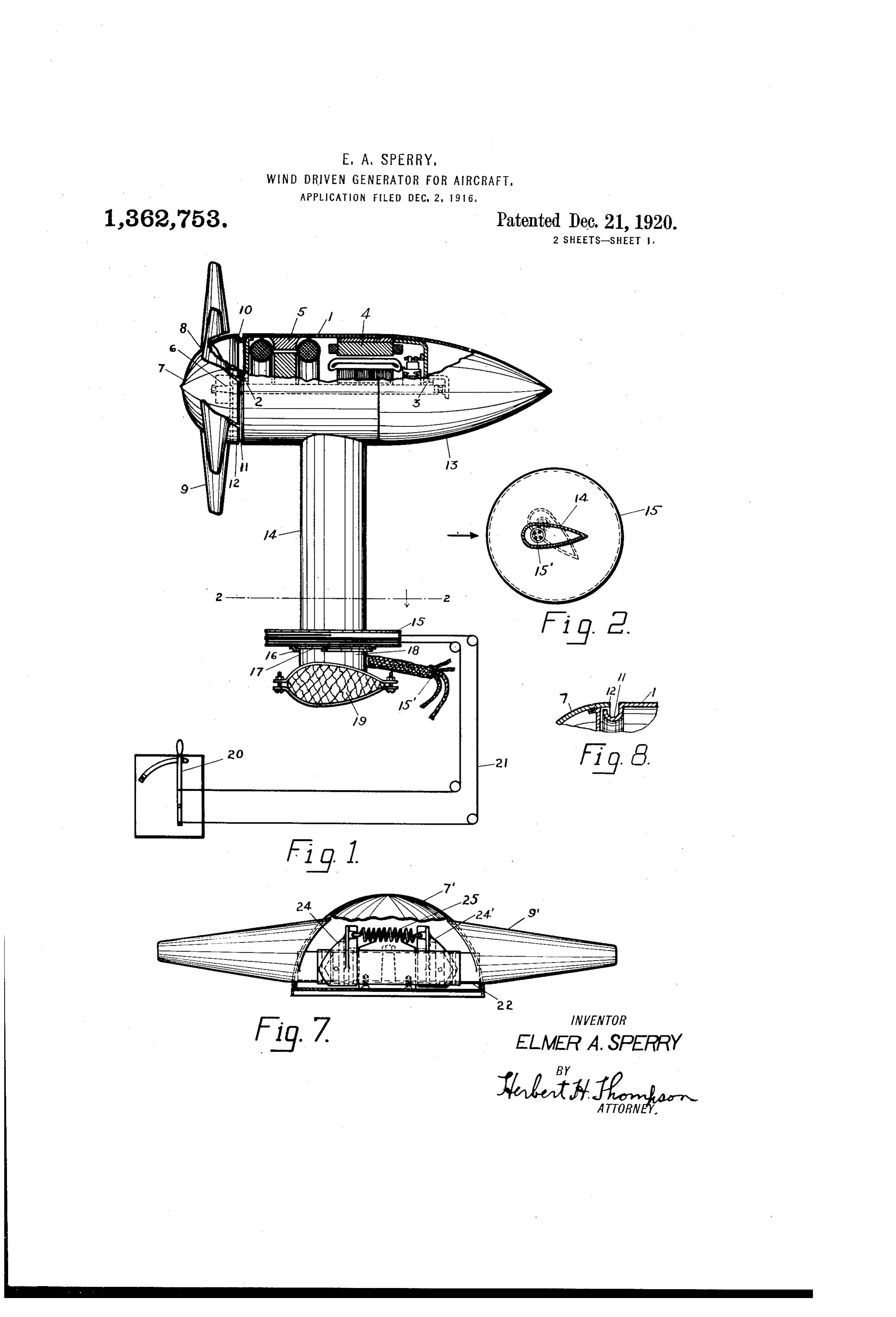
To all whom it may concern: type. On the forward end of the generator Be it known that I, ELMER A. SPERRY, a shaft 6 is mounted the hub 7 and windmill 60 citizen of the United States of America, 8. Said hub is designed especially to re residing at 1505 Albemarle road, Brooklyn, duce the head wind resistance of the gen in the county of Kings and State of New erator, and is preferably made of substan York, have invented certain new and use tially as greatItdiameter as the shell 1 of the ful Improvements in Wind-Driven Gen generator. is also preferably dome 65 erators for Aircraft, of which the follow shaped or approximately hemispherical. A plurality of blades 9 project radially there ing is a specification.
O This invention relates to a new and im from. Preferably I provide between said proved means for generating electric cur joint hub and the generator shell a waterproof rents on aeroplanes and other swiftly mov 10; that is, a joint of such character ing vehicles. As has become the case with that Water which may be splashed upon the 70 automobiles, electricity has been found to be generator will not gain entrance into the 5 an indispensible asset for aeroplanes also. interior. Said joint may consist of an It is being used for lighting signals and angular portion depression 11 in the shell, the outer of which fits within rim 12 of the other lights, operating wireless transmission revolving hub.
sets, operating the aeroplane controls The rear portion of the generator is also 75 through servo-motors, actuating various 20 kinds of instruments for signaling to other of stream line shape to reduce air resistance machines or between the pilot and observer, to minimum. It is shown as made up of operating gyroscopes, or other stabilizing detachable hollow tail piece 13, which fits apparatus, and for charging engine start over the rear portion of the generator 4 and 80 ing batteries. The object of this invention is of a tapering shape. The generating unit 25 is to provide a practicable means whereby a is supported upon a hollow stem 14 also sure supply of electricity at a constant volt The of stream line shape as shown in Fig. 2. age may be obtained. wires 15 leading into the generator are According to the present invention, it is preferably brought up through the said 85 proposed to drive a small generator by a stem. At its base said stem is preferably 30 windmill or a fan rotated by the wind caused enlarged to form, or has secured thereto, by the rapid travel of the machine. bearing plate 15, which is provided at its Referring to the drawings in which what under surface with a flanged ring 16. Said I now consider to be the preferred forms of ring is adapted to engage over a flange 17 90 my invention are shown: Figure 1 is a side On a stem 18 secured to a strut 19 or other 35 elevation partly in section of the generat part of the aeroplane. A handle 20 may be ing unit as mounted on the aeroplane. Fig. gether provided to rotate said bearing plate 15 to 2 is a section of the supporting stem on with the generator at will. For this 95 line 2-2 of Fig. 1. Fig. 3 is a plan view of purpose wires 21 or other flexible connect ing means are shown as connecting said the generator showing it turned out of its 40 normal position. Fig. 4 is a rear view of the handle with the said plate. When the gen fan showing the preferred construction of erator is placed in line with the fore and aft hub. Fig. 5 is a section of the blade on line line of the aeroplane, it is evident that it 00 will be driven at maximum speed. This
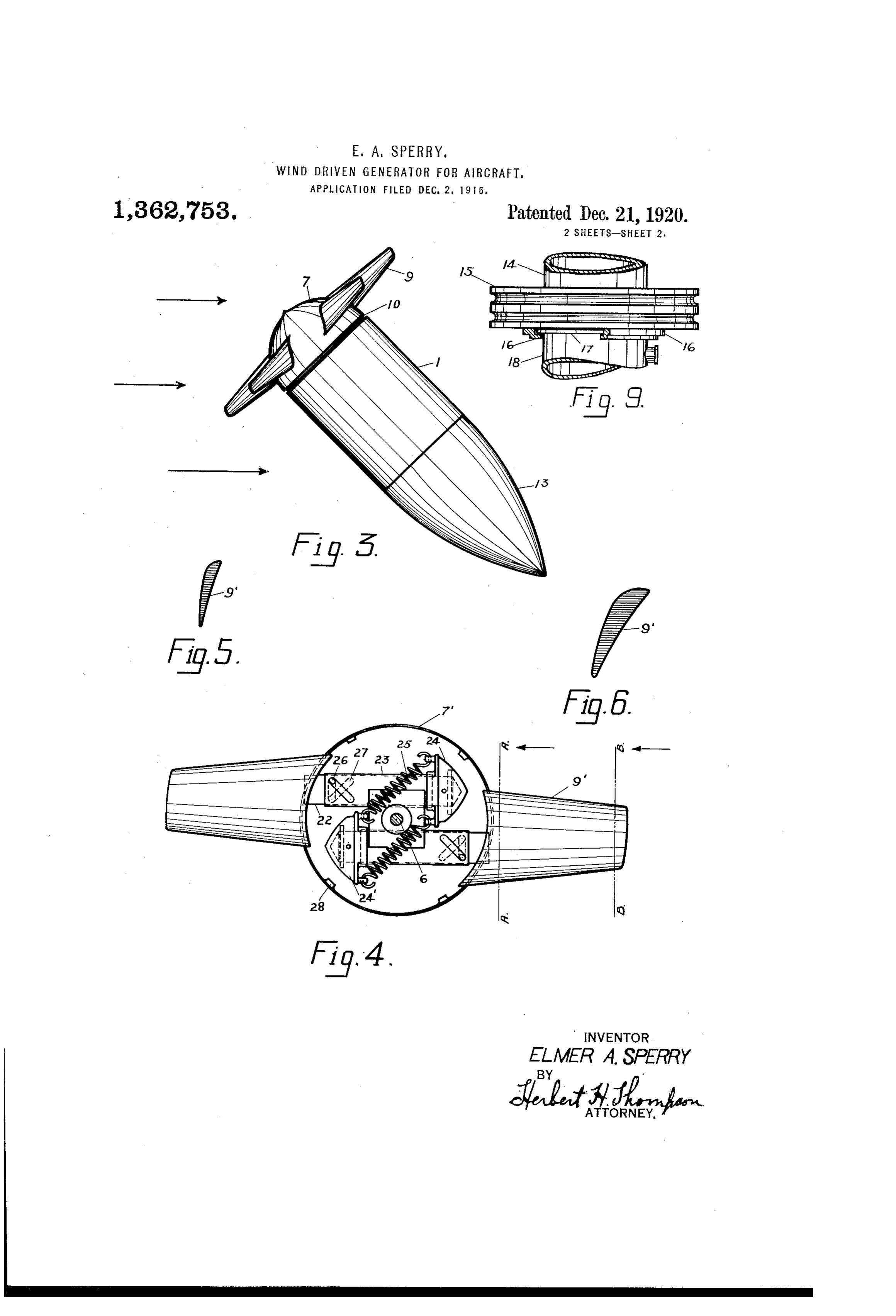
B-B Fig. 4. Fig.6 is a similar section on speed may be reduced at will by turning line A-A Fig. 4. Fig. 7 is a side elevation 45 of a fan shown in Fig. 4 partly broken away. the generator and fan out of the said fore Fig. 8 is a detail, and Fig. 9 is an enlarged and aft line as indicated in Fig. 3, the arrows representing the direction of the 105 view of a portion of Fig. 1.
The generator proper is shown inclosed wind. Ifentirely turned far enough the fan may be within tubular casing 1, which is preferably stopped or reversed. The preferred construction for the fan 50 cylindrical. Said casing supports at its for ward and rear ends the bearings 2 and 3 for and fan blades is shown in Figs. 4 to 7. The the generator shaft. In the form of the in blades are preferably secured to or form a vention shown, two machines are used to part of cylindrical stems 22 which are jour 10 make up the dynamo of the electric ma naled within sleeves 23, fixed within the 55 chine employed consisting of a direct cur hollow hub. The blades are so designed that rent generator 4, and an alternating cur their center's of gyration lie on the oppo rent generator 5 of the inductor-alternator site side of the center of shaft 6, from the
Page 4
fan portion of the blade. For this purpose the center as is generally done in pro 65 I may secure to the stem 22 a mass 24. pellers and electric fans, I find that the cen The blades are also yieldingly pressed out tral part of the blade increases the head Wardly by means of a spring or springs 25 resistance of which may extend between the mass 24 of to the added the fan out of all proportion one blade and the corresponding mass 24’ on mechanical difficultiessecured. power In addition are encountered in 70 the opposite blade. A pin and slot con broadening a blade sufficiently if carried nection 26, 27 may be provided between stem very close to the center.
22 and sleeve 23 so that longitudinal move In accordance with the provisions of the O ment of the blade will also rotate it on its longitudinal axis. Stops 28 secured to the patent statutes, I have herein described the principle of operation of my invention, to 75 interior of hub 7 may be provided to limit gether with the apparatus, which I now the movement of the blades by engaging consider to represent the best embodiment the masses 24-24'. By this construction it thereof, but I desire to have it understood 15 will readily be apparent on increase in the that the apparatus shown is only illustra speed of the fan above a predetermined tive and that the invention can be carried 80 amount, that the blades will be drawn in out by other means. Also, while it is de wardly and at the same time rotated, thus signed to use the various features and ele both reducing the area of the exposed sur ments in the combination and relations de 20 face and increasing the angle of incidence scribed some of these may be altered and whereby the resistance of the fan is de others onlitted without interfering with the 85 creased. more general results outlined, and the in The blade itself is preferably of some vention extends to such use.
what different design from standard blades Having described my invention, what I 25 used on aeroplane propellers and on elec tric fans and the like. I have found that ent claimis: and desire to secure by Letters Pat
in order to secure the maximum efficiency, 1. The combination with a wind driven that is, in order to secure the maximum generator for aeroplanes, of a tubular con power with the minimum head resistance, tainer for said generator having a tapering 30 that the blade should taper toward its tip tail portion, a forward revoluble wind di so that the quantity of air which is brought verting portion fixed to the shaft of said 95 to rest by each unit of length of the fan generator, a fan blade mounted on said for approximates the same value. In other ward portion and constant speed govern words, since the tip of the fan is revolv ing means connected with said blade for 35 ing with much greater speed than the por governing the speed of said generator. tion near the hub, it will intercept more air 2. A wind driven generator for aeroplanes 100 in the course of each revolution than the including a substantially cylindrical casing, said hub portion of the same breadth, and a dynamo electric machine and bearings hence will therefore do a greater portion of therefor supported within and by said cas 40 the work, if the blade is straight or flares ing, and a hollow stream line or tapering outwardly, as is usually the case in fans. tail piece detachably secured to said shell. 05 With such a design, the blade near the hub 3. The combination with a wind driven operates at poor efficiency. . . generator for aeroplanes, of a tubular con I have also found that a long slender tainer for said generator having a tapering 45 blade such as is usually employed in pro tail portion, a forward revoluble wind di pellers is of a disadvantage in this charac verting portion fixed to the shaft of said ter of work and that a short comparatively generator, a fan blade mounted on said broad blade is preferred. It will be seen forward portion, constant speed governing that it not only tapers in breadth toward means for normally controlling the speed of 50 its tip, but also tapers in thickness, the sec said generator, and means for varying the tions of the blades being designed with angle of incidence of said fan blade for 15 reference to the angle of incidence of the varying the speed of said generator. blade due to its helical trajectory through 4. The combination with a wind driven the air. generator for aeroplanes, of a tubular con 55 The comparatively large hub also pos tainer for said generator, a forward rev sesses other advantages than acting as a oluble wind diverting portion fixed to the 20 stream-line wind shield for the generator. shaft of said generator, a fan blade As above explained, the blades become in mounted on said forward portion and con efficient as they approach the center, unless stant speed governing means inclosed with 60 they are broadened, and even when broad in said wind diverting portion and con ened, a point is reached when I find it pref nected with said blade for governing the 25 erable to discontinue the blade and merge speed of said generator.
it into a large hub, shaped to reduce head In testimony whereof I affix my signature. resistance. If the blades are run as close to EMERASPERRY.
Provenance
- Collection
- Cited prior art
- Original PDF
- patentimages.storage.googleapis.com →
- Filed
- 1916-12-02
- Pages
- 4
- Method
- pdftotext (the PDF's own text layer) + pdftoppm 300dpi page scans
- Source
- Google Patents bibliographic record
- Granted
- 1920-12-21
- Inventors
- Elmer A Sperry
- Transcribed from
- patentimages.storage.googleapis.com →