patent · US3131942
Fluid-tight devices for rotating shafts
5 May 1964
Page 1
Drawing sheet — no readable text.
Page 2
Drawing sheet — no readable text.
Page 3
United States Patent Office 3,131,942 Patented May 5, 1964
each helicoidal groove; the result of this set of conditions 3,131,942 is not only that the molecules of gas located on each side
FLUID-TEGHT DEVICES FOR ROTATING SHAFTS of the device are no longer joined together in the central André Ertaud, Paris, France, assignor to Société Anonyme groove but also that their mixture can take place only dite: Societe Alsacienne de ConstructioBas Mecaniques, by passing through a piping system having high resistance Paris, France, a corporatiga of France to pressure and formed by the cylindrical non-grooved
Clains priority, application France Sept. 5, 1958 portion of the device. Thus any mixing of the two 11 Caimas. (C. 277-53) gases would have to take place by diffusion of the two gases into each other. Since on the one hand, this dif
In my copending application Serial No. 676,137 filed on O fusion can take place only through a high-resistance August 5, 1957 I have described a device for ensuring piping system and on the other hand, the pressures on each fluid-tightness between two media separated by a wall side of this piping system are extremely Small, the dif through which passes a rotating shaft, said device com fusion in question finally proves to be altogether negligible, prising a stator rigidly fixed to this wall in a completely with the result that, in accordance with the object which fluid-tight manner and forming a sleeve surrounding the 5 it is intended to obtain, the fluid-tightness of the device rotating shaft with a small clearance, said stator forming, is practically perfect. Moreover from the mechanical around the said shaft and substantially in its central point of view, it should be noted that the great advantage transverse plane, an annular chamber in which terminate in the present case as compared with the device described two helicoidal grooves of opposite thread and progressing in the copending application is that the clearance between respectively towards the two extremities of the stator, 20 the fixed portion and the rotating portion can be con these grooves being machined in one of the oppositely siderably increased without reducing the fluid-tightness facing surfaces of the stator or of the shaft, and having obtained, thus facilitating the utilization of the device. a depth which progressively decreases from the central The accompanying drawings, represent in axial cross annular chamber towards the extremities of the stator, section several examples of construction of a device in accessory means being provided for preventing any pas accordance with the invention applied, as in the copend Sage of gas along the rotor from one extremity of the ing application, to the isolation between, on the one hand, stator to the other when the shaft is stationary, and being the body of a rotary compressor which effects the cir arranged to come into action as soon as, or preferably culation at low pressure of a gas such as uranium hexa just before, the stopping of the said shaft takes place. fluoride, and on the other hand, an intermediate chamber When the helicoidal grooves are formed in the internal 30 filled with nitrogen at low pressure. Only those parts face of the stator, they progress towards the two extremi of the machine have been shown which are directly asso ties of Said stator in the direction of rotation of the ciated with the invention.
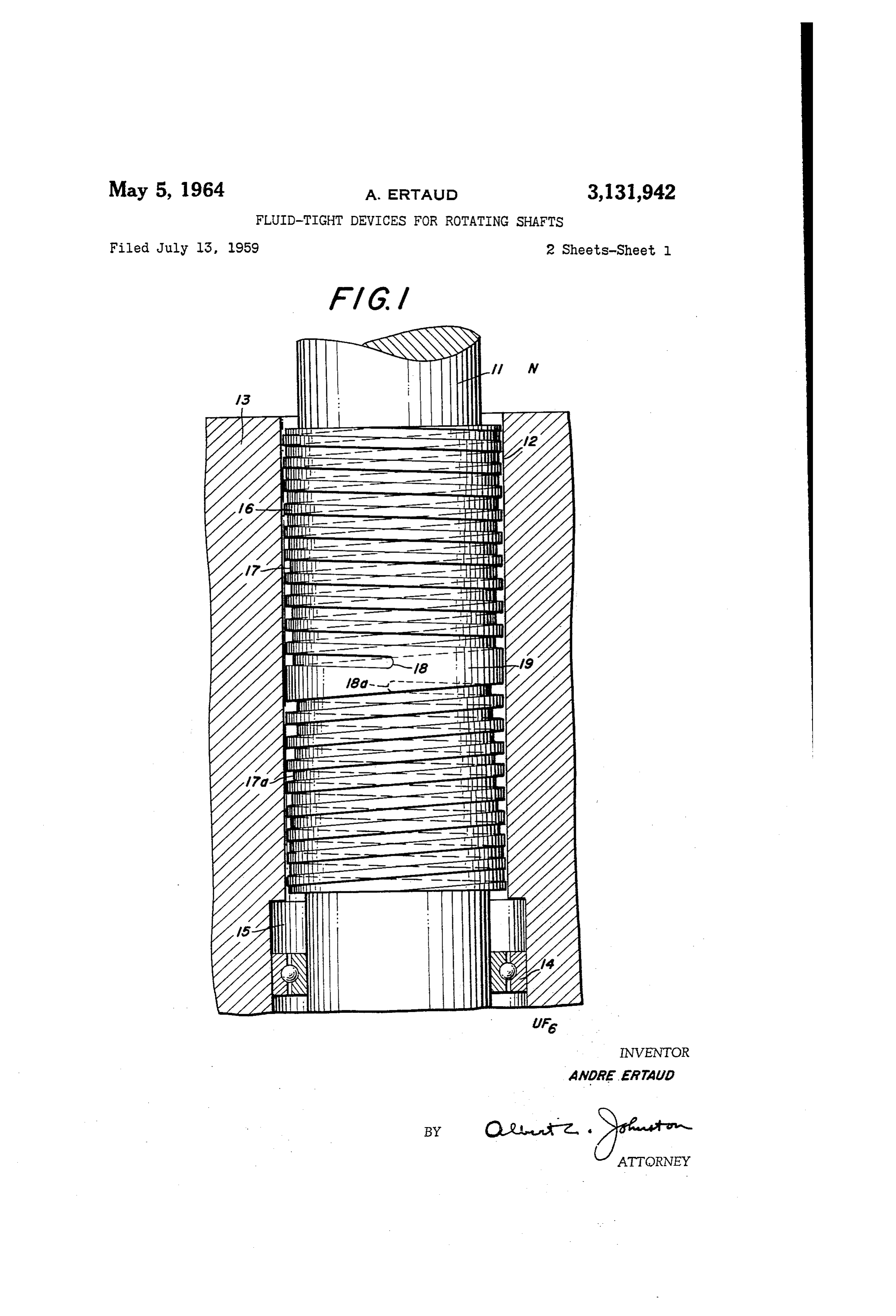
shaft. This progression takes place in the reverse direc In the drawings:
tion when the grooves are formed in the shaft. FIG. 1 illustrates an embodiment in which the grooves It has been found that certain modifications can profit 35 are formed in the rotor or shaft;
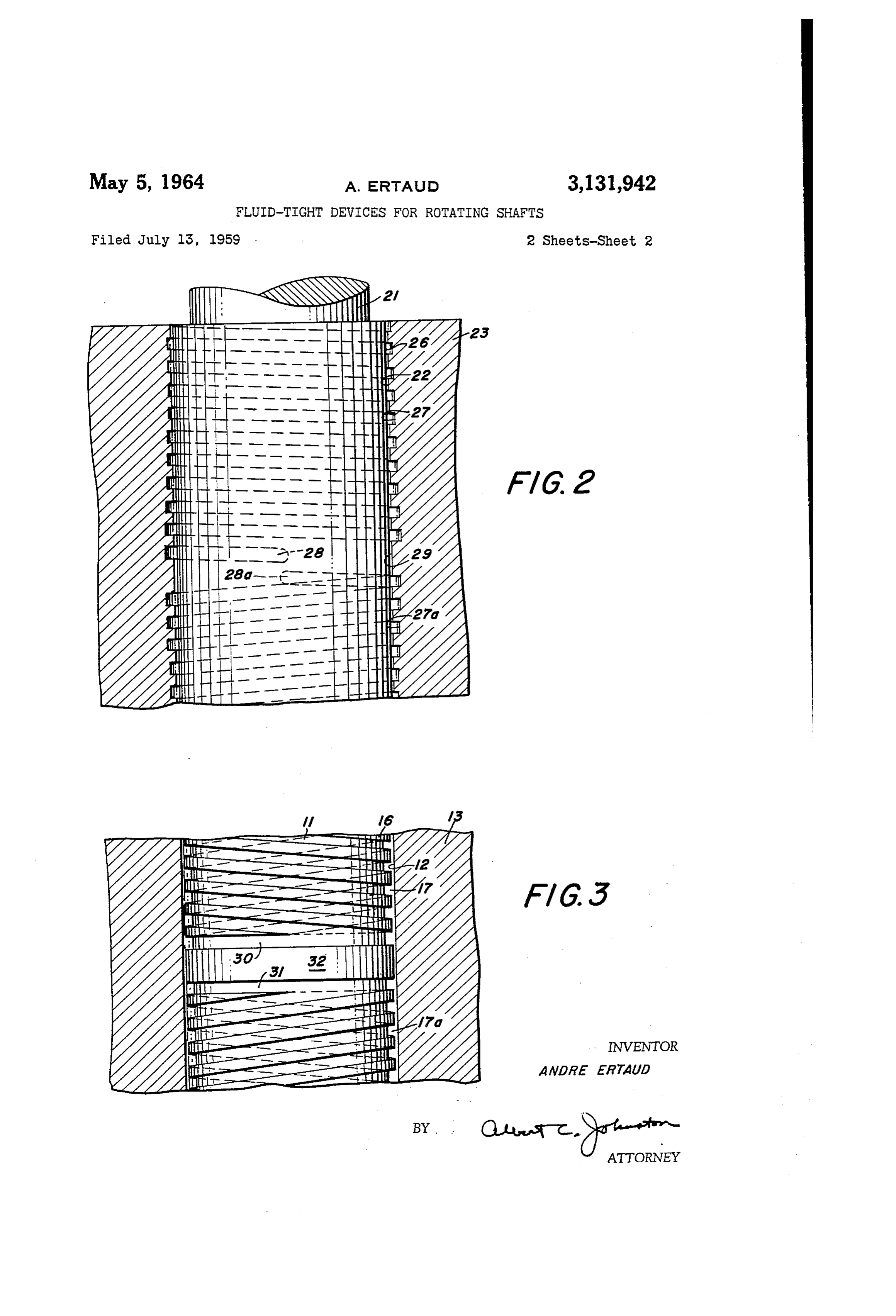
ably be carried out in the device which is thus constituted, FIG. 2 illustrates an embodiment in which the grooves thereby obtaining better results in its operation, these are formed in the internal face of the housing or stator; modifications forming the object of the present invention. and
In the first place, the central chamber can be dispensed FIG. 3 illustrates an embodiment in which the rotor or with, and the device is then constituted by a stator form 40 shaft is grooved and the inner ends of the helicoidal ing a sleeve around the rotating shaft with a small clear grooves extend from circular grooves separated by a non ance and two helicoidal grooves of opposite thread are grooved portion of the surface of the shaft. cut either in the internal surface of the stator, so as to In the example shown in FIG. 1, the compressor com progress towards the extremities of the stator in the di prises a vertical rotating shaft 11 which passes in a smooth rection of rotation of the shaft, or in the external face of 45 bore 12 through a wall 3 below which there exists an the shaft so as to progress towards the said extremities atmosphere of uranium hexafluoride UFs at an absolute in the opposite direction, starting from two points lo pressure of a few centimeters of mercury. On the upper cated respectively on two generator lines of the stator or side of the wall i3, there exists an atmosphere of nitrogen of the rotor, said generator lines being diametrically op N at a pressure equal or of the same order. The shaft 11 posite to each other and on each side of a central zone 50 is supported and centered in the bore 13 by means of on which no grooves are formed, the said grooves open a bearing 14 arranged in a widened housing 15 and is ing out at the extremities of the stator and having a depth provided in the said bore with a portion 16 of straight which progressively decreases from the said central zone section which is larger than the normal section of the towards the said extremities. shaft, so that a small clearance described in detail below, The non-grooved central zone is not necessarily located 55 is formed between the said portion 16 and the internal at the exact half-way point between the extremities of the surface of the bore 12. In this portion 16 are machined stator, and the grooved portions on each side of this zone two helicoidal grooves 17 and 17a of opposite thread, can have different lengths. On the other hand, the two respectively cut from two starting points 18 and 18.a helicoidal grooves are not necessarily symmetrical, as the located on each side of a non-grooved central zone 19. direction and absolute value of the unitary variation of 60 These two grooves each progress helicoidally from the depth can change along the course of the groove from one points 18 and 18a towards the extremities of the bore 12 extremity to the other. in the reverse direction of rotation of the shaft 11. As Finally, the non-grooved central portion can be framed as it has been indicated in the numerical table below, in by two circular grooves, into each of which opens the which the constructional characteristics of the device are helicoidal groove located on the corresponding side. 65 precisely stated, the depth of the grooves decreases in The operation of the device in accordance with the successive stages from the points of their origin 18 and invention is similar to that described in my above named 8a towards the two extremities of the bore 12 and the copending application, with this essential difference, how number of spirals of the groove 17 on the nitrogen side ever, that in the present arrangement, the high degree of is greater than that of the groove 17a on the uranium vacuum is no longer created in a central annular groove O hexafluoride side.
or chamber, but is created independently on both sides of The numerical values given below refer to the rotor the central portion of the device, at the extremities of 14 and the outline of the grooves 17 and 17a and relate
Page 4
to an example of the device designed to ensure fluid is similar to that of FIG. 1, excepting that its helicoidal tightness in the case of the application mentioned above, grooves are formed in the inner face of the stator or the pressures of nitrogen and uranium hexafluoride exist housing rather than in the rotor or shaft. Structures ing on each side of the device being both equal to 40 mm. corresponding substantially to those designated by the nu- : hg and the speed of rotation of the shaft being 6,000 r.p.m. merals 1-3 and 6-19 in FIG. 1 are designated in FIG. 2, respectively, by the numerals 21-23 and 26-29.
Clearance between rotor 5 and wall of bore 2---- 0.06 The embodiment of the invention illustrated in FIG. 3 Length of rotor 5-------------------------- 300 is similar to that of FIG. 1, excepting that the helicoidal Diameter of the rotor ------------------------- 40 grooves 7 and 17a extend from circular grooves 30 and Pitch of helicoidal grooves --------------------- 15 31 at their respective inner extremities, and a smoothly Width of grooves ---------------------------- 7.5 cylindrical central part 32 of the surface of the rotor or Number of spirals of the groove 7 on the nitrogen enlarged shaft portion 16 separates the two circular side -------------------------------------- 7 grooVes.
What we claim is:
Namely: 1. In a device for ensuring fluid-tightness between two
Min. chambers containing migratory gaseous media, wherein 3 Spirals of constant depth ------------------ 0.7 the chambers are separated by a wall traversed by a rotat 4 spirals progressively increasing from -- 0.7 to 4 ing shaft: a stator member forming a sleeve around said 3 spirals of constant depth -------------------- 4 rotating shaft with a small clearance between the stator Number of spirals of the groove 17a on the UF 20 and the shaft; said sleeve being imperforate between its side ------------------------------------ 8.5 ends; two helicoidal grooves having opposite directions Namely: of thread formed in the internal surface of said sleeve, and progressing respectively towards the two extremities
Mm. of said sleeve in the direction of rotation of said shaft, 3 Spirals of constant depth ------------------ 0.7 said grooves starting respectively from two diametrically 3% spirals progressively increasing from -- 0.7 to 7 opposite generator lines of the internal surface of said 1% spiral of constant depth ------------------ 7 sleeve and from the opposite sides of a non-grooved cen The parameters which are given above in detail are in tral zone of said surface, said grooves respectively open each particular case calculated as a function of the pres ing at the sleeve extremities and having a depth which sure of the chambers to be separated, also of the pressure 30 progressively decreases from said central zone to said required in the central portion to limit the leakage to the extremities, whereby the rotation of said shaft creates a value which it is desired to obtain, of the clearance se substantial vacuum at the inner extremity of each of said lected between the stator and rotor, of the diameter grOOVeS. -
of the rotor, of its speed of rotation and of the nature of 2. In a device for ensuring fluid-tightness between two the gases to be separated. 35 chambers containing migratory gaseous media, wherein When the above data are modified, the different param the chambers are separated by a wall traversed by a rotat eters are also subjected to variations, the effect of which ing shaft: a stator member forming a sleeve around can be qualitatively defined as follows: said rotating shaft with a small clearance between the stator and the shaft; said sleeve being imperforate be
An increase of pressure of the chambers to be separated, 40 tween for a pre-determined clearance, necessitates an increase directions its ends; two helicoidal grooves having opposite in the number of spirals having a constant depth at the shaft and ofprogressing thread formed in the external surface of said respectively towards the two ex- .
two extremities and therefore an increase in the length tremities of said sleeve in the direction opposite to the
A reduction of the pressure required in the central portion 45 direction of rotation of said shaft, said grooves starting respectively from two diametrically opposite generator necessarily entails an increase in the number of spirals lines of the external surface of said shaft and from the . of constant depth in the central portion corresponding opposite sides of a non-grooved central zone of said sur to each of the gases to be separated; - face, said grooves respectively opening at the sleeve ex An increase in the clearance between the rotor and the tremities and having a depth which progressively de stator necessitates an increase in the total number of 50 creases from Said central zone to said extremities, where the spirals and therefore an increase in the length of by the rotation of said shaft creates a substantial vacuum the rotor, should it be necessary to retain the same pres at the inner extremity of each of said grooves. sure at the center and the same counter-pressures at the 3. In a device for insuring fluid-tightness between two two extremities; chambers containing migratory gaseous media, wherein An increase in the speed of rotation, for a predetermined 55 the chambers are separated by a wall traversed by a rotat clearance and a given diameter of rotor, improves the ing shaft member;
efficiency of the pump and can permit of a reduction of a totally fluid tightamanner stator member fixed in said wall in and forming an imperforate the number of spirals and therefore a reduction in the length of the rotor. sleeve around said rotating shaft member with a small clearance between the adjacent surfaces of said members;
As far as the nature of the gases to be separated is 60 two helicoidal grooves formed in one of said surfaces and concerned, the apparatus is considerably more effective having opposite directions of thread and progressing re in the central portion for heavy gases. For these latter, Spectively towards the two extremities of said sleeve, said the number of spirals of this portion is smaller than the grooves starting respectively from two diametrically op number of spirals corresponding to a light gas; on the posite generator lines of said one surface and from the other hand, these same spirals should be deeper for heavy 65 opposite sides of a non-grooved central zone of said one gas. surface, said grooves respectively opening at the sleeve The following parameters: pitches of helicoidal grooves, extremities and having a depth which progressively de width of grooves, have been determined empirically and creases fron said central zone to said extremities, where can be considered as fixed. by upon rotation of said shaft at high speed in the direc Finally, in view of the fact that the phenomenon of O tion to lead gaseous molecules away from said central the entrainment of molecules by a moveable wall depends Zone a substantial vacuum is created in each of said on the linear speed of the wall, it is obvious that the grooves at the inner extremity thereof and gaseous com speed of rotation of the rotor and the diameter of the rotor are not independent factors. . . . munication between said grooves is obstructed by said central Zone.
The embodiment of the invention illustrated in FIG. 2 75 4. A device as claimed in claim 3, in which said
Page 5
grooves on each side of said central zone are of differ tive rotation of said nembers at high speed creates a sub ent lengths. stantial vacuum at each of said inner extremities. 5. A device as claimed in claim 3, in which said 10. Apparatus comprising a housing member and a grooves on each side of said central zone are asym rotatable shaft member, said ihousing member having a metrical. bore therethrough and said shaft member extending 6. A device as claimed in ciain 3, in which said non tihrough said bore and having a diameter less than that of grooved central zone is delimited axially by two circular Said bore and thereby defining a clearance space within grooves from which start respectively the corresponding Said housing member, one of said members being pro helicoidal grooves. vided with oppositely directed helicoidal grooves extend 7. A device as claimed in claim 3, in which the sense IO ing in opposite directions around and along said bore and the absolute value of the variation in depth per unit from a portion of the surface of said one member dis length of said helicoidal grooves vary from one extremity posed between the inner extremities of said grooves, said of each groove to the other. surface portion comprising a central part lying close to 8. Apparatus for ensuring fluid-tightness between two the other of Said members and an annular groove at chambers containing migratory fluid media, comprising 5 either side of said central part, said helicoidal grooves a housing member and a rotatable shaft member, said opening into said annular grooves at said inner ex holising meinber being adapted to form part of a wall tremities, whereby gaseous conin munication between said Separating said chanbers and having a bore therethrough helicoidal grooves is obstructed by said central part and and being imperforate between the ends of said bore, relative rotation of said members at high speed creates Said shaft member extending through said bore and hay a Substantial vacuum at each of said inner extremities. ing a diameter less than that of said bore and thereby 11. Apparatus comprising a housing member and a defining a clearance space within said housing member, rotatable shaft member, said housing member having a one of said members being provided with oppositely di bore theretirough and said shaft member extending rected helicoidal grooves extending in opposite directions through said bore and having a diameter less than that around and along said bore from a portion of the sur 25 of Said bore and thereby defining a clearance space with face of said one member at the inner extremities of said in said housing member, one of said members being pro grooves, said surface portion comprising a central part vided with oppositely directed helicoidal grooves extend lying close to the other of said members, whereby gaseous ing in opposite directions around and along said bore communication between said grooves is obstructed by 30 from a portion of the surface of said one member dis Said central part and the relative rotation of said mem posed between the inner extremities of said grooves, said bers at high speed creates a substantial vacuum at each Suliface portion comprising a central part lying close to of said inner extremities. the other of said members and an annular groove at 9. Apparatus for ensuring fluid-tightness between two either side of said central part, said helicoidal grooves chambers containing migratory fluid media, comprising opening into said annular grooves at said inner extremities a housing member and a rotatable shaft member, said 35 and having depths which increase toward said extremities, housing member being adapted to form part of a wall whereby gaseous communication between saidi helicoidal separating said chambers and having a bore therethrough grooves is obstructed by said central part and relative and being imperforate between the ends of said bore, rotation of said members at high speed creates a sub said shaft member extending through said bore and hav 40 stantial vacuum at each of said inner extremities. ing a diameter less than that of said bore and thereby defining a clearance space within said housing member, References Cited in the file of this patent one of said members being provided with oppositely di UNITED STATES PATENTS rected helicoidal grooves extending in opposite directions 391,071 Parsons --------------- Oct. 16, 1888 around and along said bore from a portion of the sur 45 752,170 Krogh ---------------- Feb. 16, 1904 face of said one member at the inner extremities of said 2,064,703 Van De Graaff ----------- Dec. 15, 1936 grooves, Said Surface portion comprising a central part 2,487,177 POlIOck ----------------- Nov. 8, 1949 lying close to the other of said members and said grooves having depths which increase toward said inner ex FOREIGN PATENTS tremities, whereby gaseous communication between said 148,932 Great Britain ----------- Oct. 10, 1921 grooves is obstructed by said central part and the rela 491,366 Germany -------------- Feb. 10, 1930
Provenance
- Collection
- Cited prior art
- Original PDF
- patentimages.storage.googleapis.com →
- Filed
- 1959-07-13
- Pages
- 5
- Method
- pdftotext (the PDF's own text layer) + pdftoppm 300dpi page scans
- Source
- Google Patents bibliographic record
- Granted
- 1964-05-05
- Inventors
- Ertaud Andre; Alsacienne de Constructions Mecaniques SA
- Transcribed from
- patentimages.storage.googleapis.com →