patent · US2842214
Rotor blade with deicing means
8 July 1958
Page 1
Drawing sheet — no readable text.
Page 2
Drawing sheet — no readable text.
Page 3
Drawing sheet — no readable text.
Page 4
United States Patent Office 2,842,214 Patented July 8, 1958
preferably in a generally flat vertical wall 3'. A thin sheet 4 of metal such, illustratively, as of stainless steel 2,842,214 is completely wrapped around the formed nose member ROTOR BLADE WITS DECNG MEANS 3 and attached thereto by suitable adhesive. The stain 5 less steel sheet 4 may extend to the trailing edge 5, or to
Richard H. Prewitt, Wallingford, Pa. any position short of the trailing edge, provided suitable Original application June 28, 1947, Seria No. 724,836, supporting structure is used to maintain and support the external contour of the blade.
- vided
and this application May 7, 1953, Serial No. 0 An external telescoping collar 6 is fitted over the in 353,577 board end of the tubular member 2 and suitably attached
such as by welding, as shown, or other suitable means.
The function of this collar is to transmit the centrifugal loads from the blade to its inboard connection, such as
shown at 7, Figure 2. At the outboard end of blade 1,
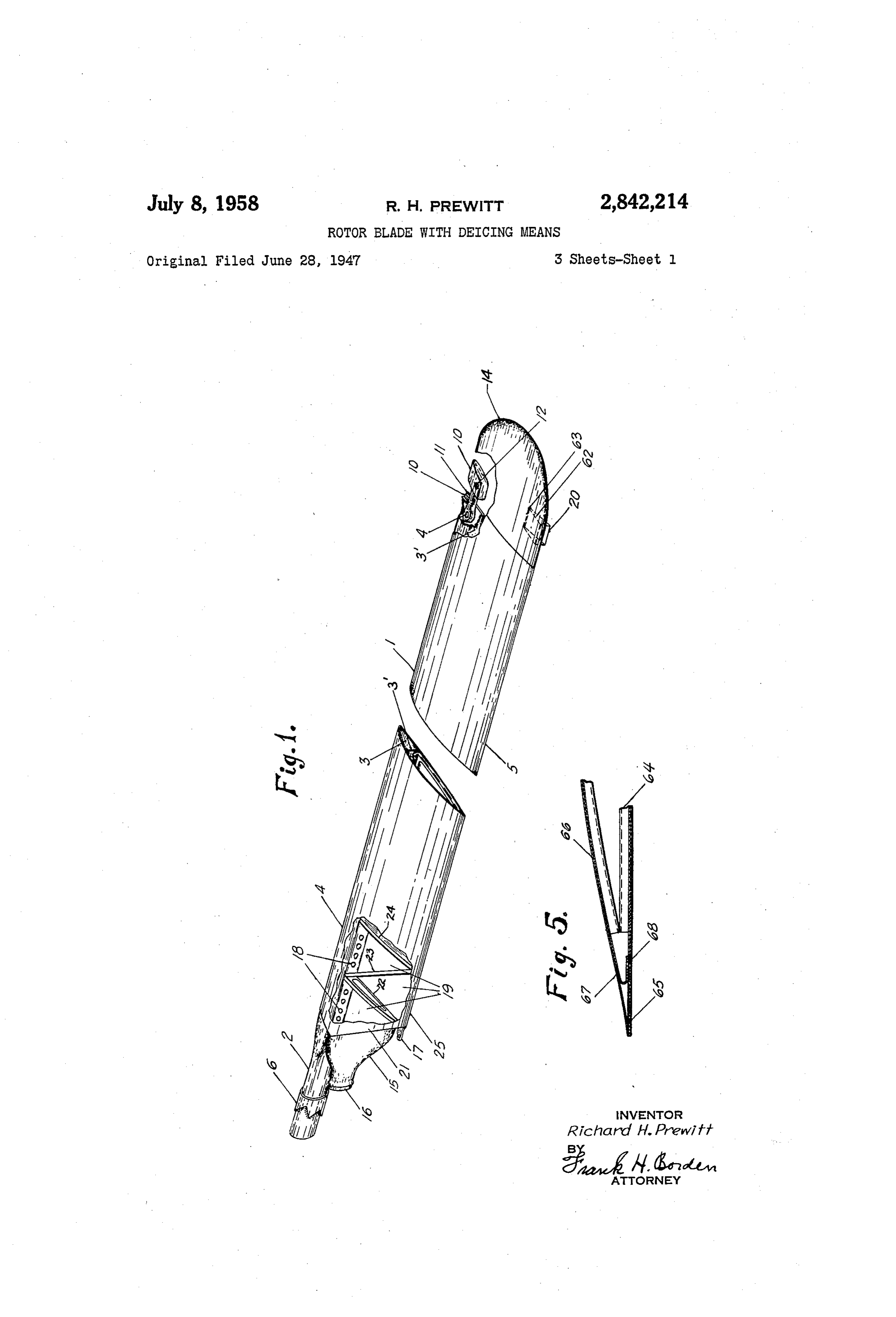
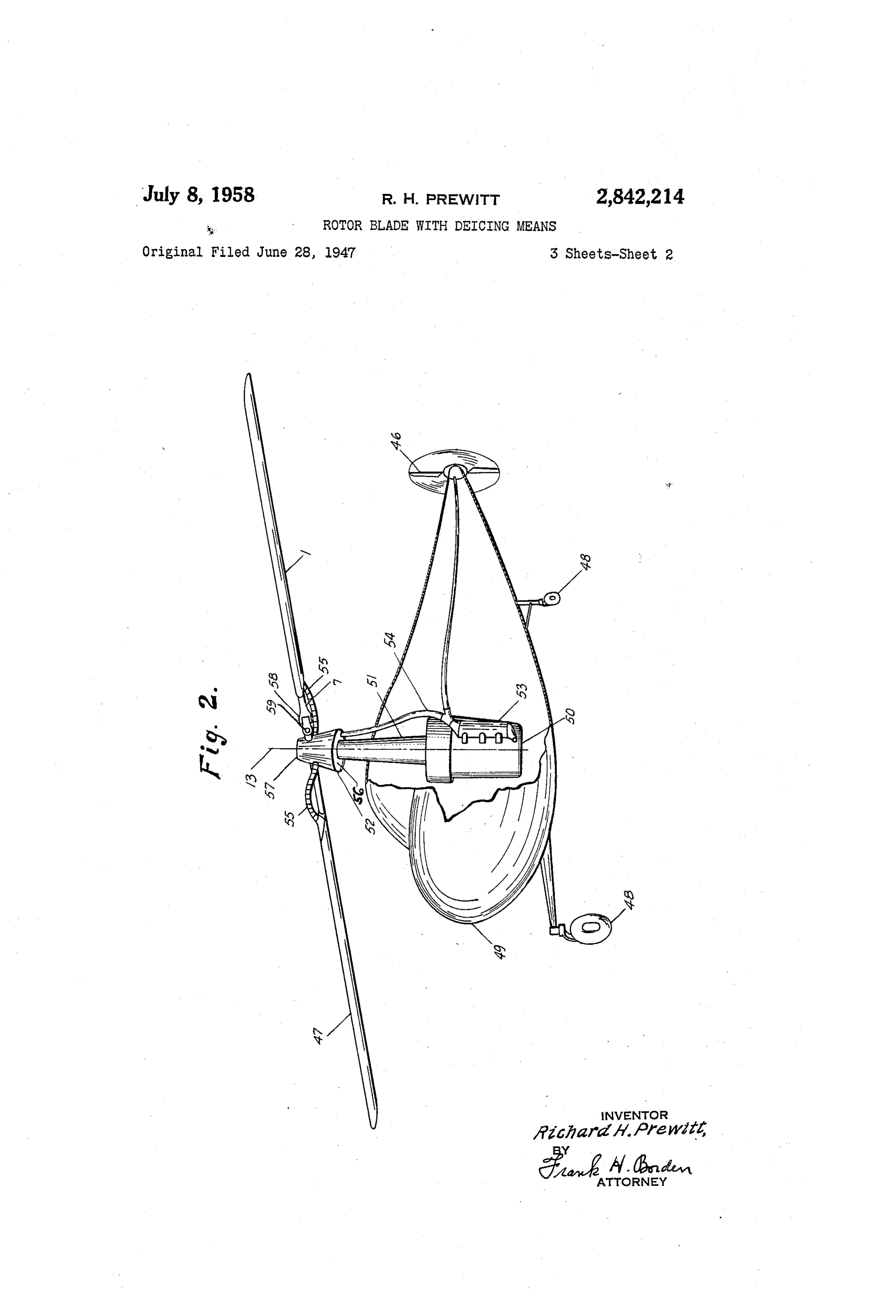
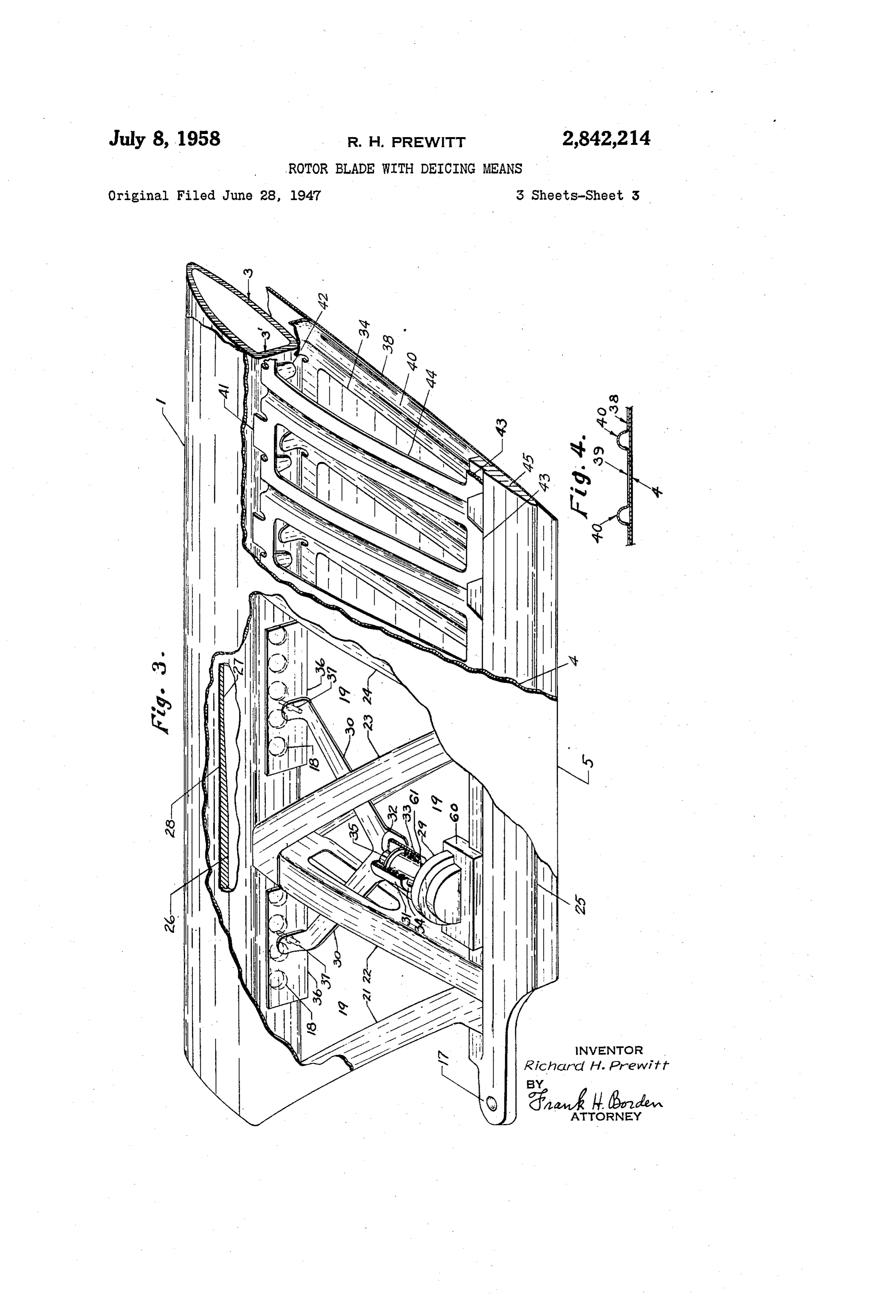
This invention relates to aircraft propellers or rotors, Weight 8 is attached to formed spar tube 3 at pivot 9. and is more particularly concerned with features of blade. . Adjusting screw 10 is adjusted through bushing 11, which construction, as fully described hereinafter. This appli forms a part of nose airfoil shaped member 3. The cen cation constitutes a division of application Ser. No. ter of gravity 12 of weight 8 lies slightly aft of a theo 724,836, filed June 28, 1947, now matured into Patent 20 retical line passing between the axis of rotation of the No. 2,638,170, of May 12, 1953. rotor 13, Figure 2, and pivot 9 so that in operation a In the past considerable difficulty has been experienced continual force is exerted on weight 8, tending to move with blade failures occurring at the inboard end between it forward against adjusting screw 10. Thus, when the the blade proper and the structure near the hub to which adjusting screw 10 is turned in a tightening sense, the the blade is attached. These difficulties have been Weight is forced aft, and when the adjusting screw is brought about as a result of fatigue risers occurring at 25 turned in a loosening sense, the weight is permitted to abrupt section changes, as where pins or rivets or flanges move forward with the aid of centrifugal force acting are used to transfer the load from the blade proper to the upon it around its pivot 9. The tip of the blade is made inboard attaching structure. In order to avoid structural of two formed members 14, suitably mated and attached failures the weight of the blade attaching structure be 30 to main cover 4 and nose airfoil shaped member 3 with comes excessive where existing fatigue risers are present. screws to permit changing the size of the weight member The method of transforming from a round husky struc 8 to account for variation in the longitudinal balance of tural member (suitable for mating a machined part) to the blade 1, resulting from manufacturing weight devia the main structural assembly of the blade proper, as tions. Adjustable weight member 8 is used to obtain taught in this invention, advances the art of rotor blade proper chordwise center of gravity for blade it. The fabrication tremendously since many fatal accidents may 35 effectiveness of moving a small weight fore and aft near be avoided due to the obviously better control over in the tip of the blade is great, relative to fore and aft spection and assembly of the simple parts disclosed in movement of similar weights located near the axis of this invention. In addition, considerable weight can be rotation 13, Figure 2. ' saved, both at the inboard connection and throughout 40 At the inboard end of the blade, manifold 15 receives the blade. The latter weight saving is accomplished due and transmits hot gases from a suitable source through to the fact that proper chordwise balance can be accom flexible tubing 55, (Figure 2) attached at 16, and directs plished without the use of nose weights which do not con the hot gases into the aft inboard section of the blade at tribute to the blade strength yet require a part of the i9 from which the gases are sucked through holes 38 remaining blade strength to carry the centrifugal and lying along the neutral axis of the nose airfoil shaped inertia forces that they exert on the hub. member. The centrifugal force acting on the column of It is among the objects of the invention; to provide a hot gases within the nose airfoil shaped member 3 creates blade with a conduit for conducting hot gases under the a suction which draws the hot gases through the leading control of thermostatic means and to provide a blade edge of the blade, and out alltomatically adjusted vent with a conduit for conducting hot gases with a valve con 50 20 located at or near the tip of the blade. In an alternate trolling exhaust of gases from the conduit positioned construction the manifold 15 and holes as may be elimi ibetween closed and open according to the sense of the nated, and the hot gases may pass directly through the differential between aerodynamic pressures external of tube member 2 and the nose airfoil shaped member 3. the blade and gas pressures in said conduit. Experience has shown that the inboard end of the blade Figure 1 shows a perspective view of a propeller or is subject to more than ordinary punishment due to the rotor blade. Figure 2 shows a partially completed ele 55 bending moments in the plane of rotation, resulting from vation perspective view of a helicopter, incorporating the blade dampers; or, in the case of rigid rotors, from the features of this invention. Figure 3 shows a cutaway Structural restraint against the natural tendency of the perspective view of the internal end of the blade shown blades to move relative to each other in the plane of in Figure 1. Figure 4 shows a cross section of the stiffen rotation. The blade of this invention shows stiffening ing members shown in Figure 3; and Figure 5 is an alter 60 structure at its inboard end, as illustrated by reinforcing nate modified construction of the trailing edge structure ribs 21, 22, 23, and 24, and trailing edge member 25. A shown in Figure 3. . .' . fitting 17 is incorporated in the blade either to provide The blade construction taught in this invention involves a blade damper attachment point or to provide additional the forming of a tubular member 2 into a nose airfoil means of relieving stresses in the tubular member 2, or shaped member 3 which maintains the external contour. 65 'for increasing the stiffness of the blade in the plane of of the blade in its forward section. The tube is prefer rotation. Exit slot 20 may be arranged to automatically ably a single integral tube formed by drawing operations close when the deicing system is inoperative, and to auto into a plurality of portions having respectively different matically open for exhausting the spent hot gases when sectional profiles, one of which, at the root, is cylindrical the deicing system is operative. This is accomplished or annular, and another of which is as of an airfoil nose O by locating the hinged door 62 comprising a hinge at section terminating toward the trailing edge of the blade, 63, which under normal operating conditions will be
Page 5
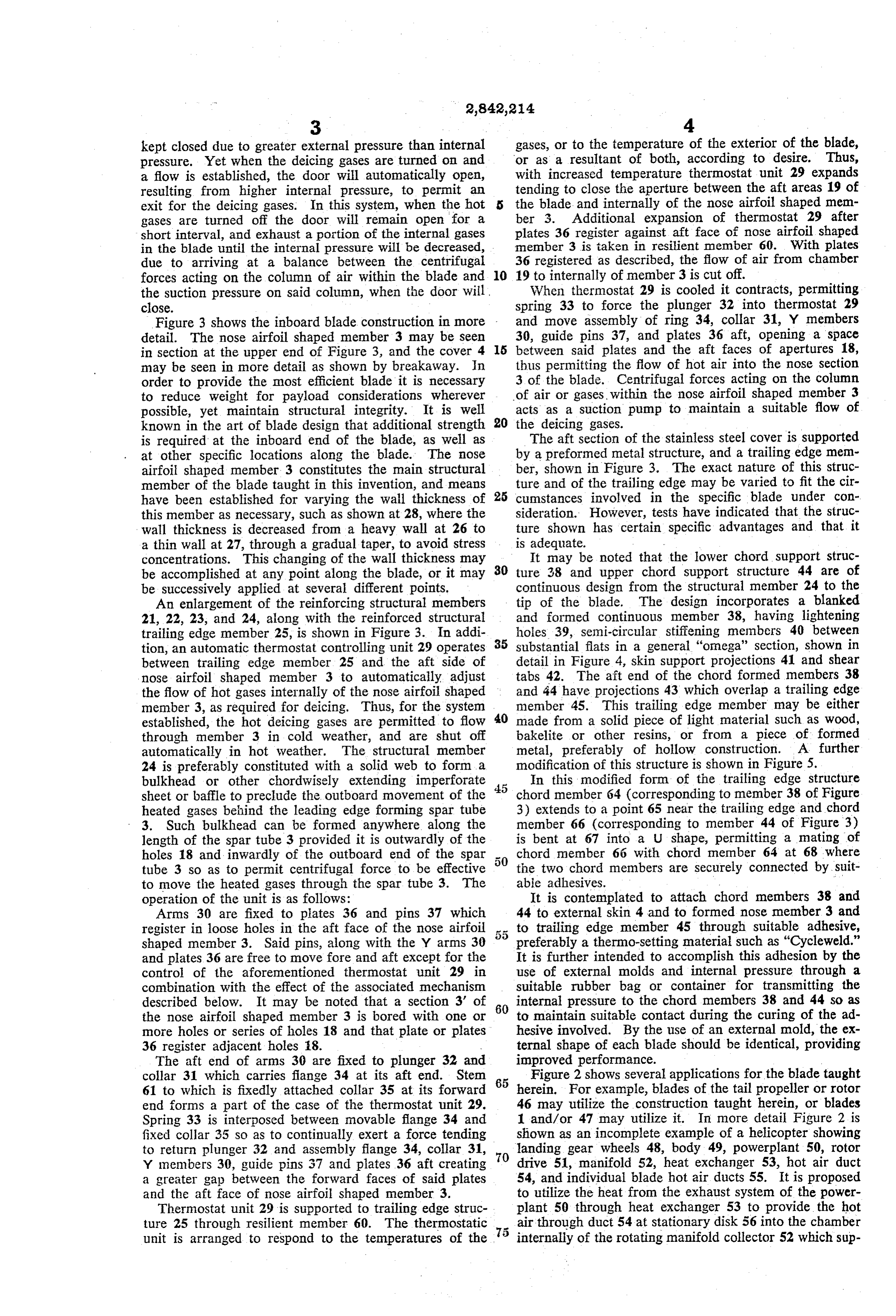
kept closed due to greater external pressure than internal gases, or to the temperature of the exterior of the blade, pressure. Yet when the deicing gases are turned on and or as a resultant of both, according to desire. Thus, a flow is established, the door will automatically open, with increased temperature thermostat unit 29 expands resulting from higher internal pressure, to permit an tending to close the aperture between the aft areas 19 of exit for the deicing gases. In this system, when the hot s the blade and internally of the nose airfoil shaped mem gases are turned off the door will remain open for a ber 3. Additional expansion of thermostat 29 after short interval, and exhaust a portion of the internal gases plates 36 register against aft face of nose airfoil shaped in the blade until the internal pressure will be decreased, member 3 is taken in resilient member 60. With plates due to arriving at a balance between the centrifugal 36 registered as described, the flow of air from chamber forces acting on the column of air within the blade and 10 19 to internally of member 3 is cut off. the suction pressure on said column, when the door will. When thermostat 29 is cooled it contracts, permitting close. spring 33 to force the plunger 32 into thermostat 29 Figure 3 shows the inboard blade construction in more and move assembly of ring 34, collar 31, Y members detail. The nose airfoil shaped member 3 may be seen 30, guide pins 37, and plates 36 aft, opening a space in section at the upper end of Figure 3, and the cover 4 5 between said plates and the aft faces of apertures 18, may be seen in more detail as shown by breakaway. In thus permitting the flow of hot air into the nose section order to provide the most efficient blade it is necessary 3 of the blade. Centrifugal forces acting on the column to reduce weight for payload considerations wherever of air or gases, within the nose airfoil shaped member 3 possible, yet maintain structural integrity. It is well acts as a suction pump to maintain a suitable flow of known in the art of blade design that additional strength 20 the deicing gases.
is required at the inboard end of the blade, as well as The aft section of the stainless steel cover is supported at other specific locations along the blade. The nose by a preformed metal structure, and a trailing edge mem airfoil shaped member 3 constitutes the main structural ber, shown in Figure 3. The exact nature of this struc member of the blade taught in this invention, and means ture and of the trailing edge may be varied to fit the cir have been established for varying the wall thickness of 25 cumstances involved in the specific blade under con this member as necessary, such as shown at 28, where the sideration. However, tests have indicated that the struc wall thickness is decreased from a heavy wall at 26 to ture shown has certain specific advantages and that it a thin wall at 27, through a gradual taper, to avoid stress is adequate.
concentrations. This changing of the wall thickness may It may be noted that the lower chord support struc be accomplished at any point along the blade, or it may 30 ture 38 and upper chord support structure 44 are of be successively applied at several different points. continuous design from the structural member 24 to the An enlargement of the reinforcing structural members tip of the blade. The design incorporates a blanked 21, 22, 23, and 24, along with the reinforced structural and formed continuous member 38, having lightening trailing edge member 25, is shown in Figure 3. In addi holes 39, semi-circular stiffening members 40 between tion, an automatic thermostat controlling unit 29 operates 35 substantial flats in a general "omega" section, shown in between trailing edge member 25 and the aft side of detail in Figure 4, skin support projections 41 and shear nose airfoil shaped member 3 to automatically adjust tabs 42. The aft end of the chord formed members 38 the flow of hot gases internally of the nose airfoil shaped and 44 have projections 43 which overlap a trailing edge member 3, as required for deicing. Thus, for the system member 45. This trailing edge member may be either established, the hot deicing gases are permitted to flow 40 made from a solid piece of light material such as wood, through member 3 in cold weather, and are shut off bakelite or other resins, or from a piece of formed automatically in hot weather. The structural member metal, preferably of hollow construction. A further 24 is preferably constituted with a solid web to form a modification of this structure is shown in Figure 5. bulkhead or other chordwisely extending imperforate In this modified form of the trailing edge structure sheet or baffle to preclude the outboard movement of the chord member 64 (corresponding to member 38 of Figure heated gases behind the leading edge forming spar tube 3) extends to a point 65 near the trailing edge and chord 3. Such bulkhead can be formed anywhere along the ismember 66 (corresponding to member 44 of Figure 3) bent at 67 into a U shape, permitting a mating of length of the spar tube 3 provided it is outwardly of the holes 18 and inwardly of the outboard end of the spar chord member 66 with chord member 64 at 68 where tube 3 so as to permit centrifugal force to be effective the two chord members are securely connected by suit to move the heated gases through the spar tube 3. The able adhesives.
operation of the unit is as follows: It is contemplated to attach chord members 38 and Arms 30 are fixed to plates 36 and pins 37 which 44 to external skin 4 and to formed nose member 3 and register in loose holes in the aft face of the nose airfoil to trailing edge member 45 through suitable adhesive, shaped member 3. Said pins, along with the Y arms 30 preferably a thermo-setting material such as "Cycleweld." and plates 36 are free to move fore and aft except for the It is further intended to accomplish this adhesion by the control of the aforementioned thermostat unit 29 in use of external molds and internal pressure through a combination with the effect of the associated mechanism suitable rubber bag or container for transmitting the described below. It may be noted that a section 3' of 60 internal pressure to the chord members 38 and 44 so as the nose airfoil shaped member 3 is bored with one or to maintain suitable contact during the curing of the ad more holes or series of holes 18 and that plate or plates hesive involved. By the use of an external mold, the ex 36 register adjacent holes 8. - ternal shape of each blade should be identical, providing The aft end of arms 30 are fixed to plunger 32 and improved performance.
collar 31 which carries flange 34 at its aft end. Stem Figure 2 shows several applications for the blade taught 61 to which is fixedly attached collar 35 at its forward 65 herein. For example, blades of the tail propeller or rotor end forms a part of the case of the thermostat unit 29. 46 may utilize the construction taught herein, or blades Spring 33 is interposed between movable flange 34 and 1 and/or 47 may utilize it. In more detail Figure 2 is fixed collar 35 so as to continually exert a force tending shown as an incomplete example of a helicopter showing to return plunger 32 and assembly flange 34, collar 31, 70 landing gear wheels 48, body 49, powerplant 50, rotor Y members 30, guide pins 37 and plates 36 aft creating drive 51, manifold 52, heat exchanger 53, hot air duct a greater gap between the forward faces of said plates 54, and individual blade hot air ducts 55. It is proposed and the aft face of nose airfoil shaped member 3. to utilize the heat from the exhaust system of the power Thermostat unit 29 is supported to trailing edge struc plant 50 through heat exchanger 53 to provide the hot ture 25 through resilient member 60. The thermostatic air through duct 54 at stationary disk 56 into the chamber unit is arranged to respond to the temperatures of the 75 internally of the rotating manifold collector 52 which sup
Page 6
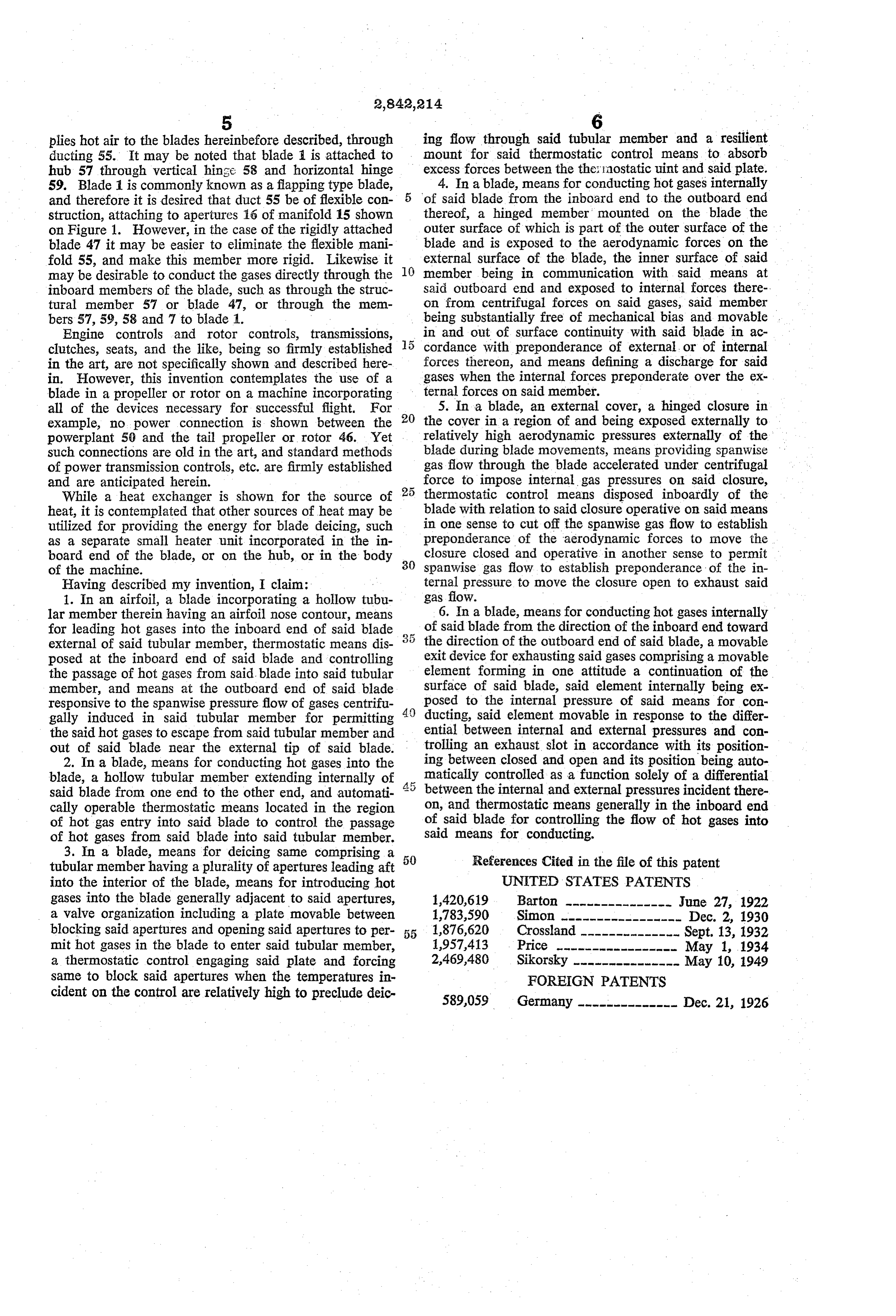
plies hot air to the blades hereinbefore described, through ing flow through said tubular member and a resilient ducting 55. It may be noted that blade is attached to mount for said thermostatic control means to absorb hub 57 through vertical hinge 58 and horizontal hinge excess forces between the the: inostatic uint and said plate. 59. Blade 1 is commonly known as a flapping type blade, 4. In a blade, means for conducting hot gases internally and therefore it is desired that duct 55 be of flexible con of said blade from the inboard end to the outboard end struction, attaching to apertures 16 of manifold 15 shown thereof, a hinged member mounted on the blade the on Figure 1. However, in the case of the rigidly attached outer surface of which is part of the outer surface of the blade 47 it may be easier to eliminate the flexible mani blade and is exposed to the aerodynamic forces on the fold 55, and make this member more rigid. Likewise it 10 external surface of the blade, the inner surface of said may be desirable to conduct the gases directly through the member being in communication with said means at inboard members of the blade, such as through the struc said outboard end and exposed to internal forces there tural member 57 or blade 47, or through the mem on from centrifugal forces on said gases, said member bers 57, 59, 58 and 7 to blade 1. being Substantially free of mechanical bias and movable Engine controls and rotor controls, transmissions, in and out of surface continuity with said blade in ac clutches, seats, and the like, being so firmly established cordance with preponderance of external, or of internal in the art, are not specifically shown and described here forces thereon, and means defining a discharge for said in. However, this invention contemplates the use of a gases when the internal forces preponderate over the ex blade in a propeller or rotor on a machine incorporating ternal forces on said member.
all of the devices necessary for successful flight. For 5. In a blade, an external cover, a hinged closure in example, no power connection is shown between the 20 the cover in a region of and being exposed externally to powerplant 50 and the tail propeller or rotor 46. Yet relatively high aerodynamic pressures externally of the such connections are old in the art, and standard methods blade during blade movements, means providing spanwise of power transmission controls, etc. are firmly established gas flow through the blade accelerated under centrifugal and are anticipated herein. force to impose internal gas pressures on said closure, While a heat exchanger is shown for the source of 25 thermostatic control means disposed inboardly of the heat, it is contemplated that other sources of heat may be blade with relation to said closure operative on said means utilized for providing the energy for blade deicing, such in one sense to cut off the spanwise gas flow to establish as a separate Small heater unit incorporated in the in preponderance of the aerodynamic forces to move the closure closed and operative in another sense to permit board end of the blade, or on the hub, or in the body 30 spanwise of the machine. gas flow to establish preponderance of the in Having described my invention, I claim: ternal pressure to move the closure open to exhaust said 1. In an airfoil, a blade incorporating a hollow tubu gas flow.
lar member therein having an airfoil nose contour, means 6. In a blade, means for conducting hot gases internally for leading hot gases into the inboard end of said blade of said blade from the direction of the inboard end toward external of said tubular member, thermostatic means dis the direction of the outboard end of said blade, a movable posed at the inboard end of said blade and controlling exit device for exhausting said gases comprising a movable the passage of hot gases from said blade into said tubular element forming in one attitude a continuation of the member, and means at the outboard end of said blade Surface of said blade, said element internally being ex responsive to the spanwise pressure flow of gases centrifu 40 posed to the internal pressure of said means for con gally induced in said tubular member for permitting ducting, said element movable in response to the differ the said hot gases to escape from said tubular member and ential between internal and external pressures and con out of said blade near the external tip of said blade. trolling an exhaust slot in accordance with its position 2. In a blade, means for conducting hot gases into the ing between closed and open and its position being auto blade, a hollow tubular member extending internally of 4. 5 matically controlled as a function solely of a differential said blade from one end to the other end, and automati between the internal and external pressures incident there cally operable thermostatic means located in the region on, and thermostatic means generally in the inboard end of hot gas entry into said blade to control the passage of said blade for controlling the flow of hot gases into of hot gases from said blade into said tubular member. said means for conducting.
3. In a blade, means for deicing same comprising a References Cited in the file of this patent tubular member having a plurality of apertures leading aft 50 into the interior of the blade, means for introducing hot UNITED STATES PATENTS gases into the blade generally adjacent to said apertures, 1,420,619 Barton --------------- June 27, 1922 a valve organization including a plate movable between 1,783,590 Simon ----------------- Dec. 2, 1930 blocking said apertures and opening said apertures to per 1,876,620 Crossland-------------- Sept. 13, 1932 mit hot gases in the blade to enter said tubular member, 1957,413 Price ----------------- May 1, 1934 a thermostatic control engaging said plate and forcing 2,469,480 Sikorsky --------------- May 10, 1949 same to block said apertures when the temperatures in FOREIGN PATENTS cident on the control are relatively high to preclude deic 589,059 Germany -------------- Dec. 21, 1926
Provenance
- Collection
- Cited prior art
- Original PDF
- patentimages.storage.googleapis.com →
- Filed
- 1953-05-07
- Pages
- 6
- Method
- pdftotext (the PDF's own text layer) + pdftoppm 300dpi page scans
- Source
- Google Patents bibliographic record
- Granted
- 1958-07-08
- Inventors
- Richard H Prewitt
- Transcribed from
- patentimages.storage.googleapis.com →