patent · US3748089
Treating articles for a controlled duration
24 July 1973
Page 1 — bibliographic record
United States Patent (19) (11 3,748,089 Boyer et al. (45) July 24, 1973 54) TREATING ARTICLES FOR A 3,105,678 10/1963 Van Houten......................... 432/52
CONTROLLED DURATION
75 Inventors: Lynn F. Boyer, Reading; Charles Primary Examiner-John J. Camby R. Fegley, laureldale; Anderson Attorney-W. M. Kain et al.
F. Johnson, Jr., Sinking Spring, all of Pa.
73 Assignee: Western Electric Company, In corporated, New York, N.Y. In a method and apparatus for baking photoresist on 22) Filed: May 15, 1972 semiconductor slices, the length of baking time is con trolled independently of the number of slices being 21 Appl. No.: 253,601 baked or the position of the first slice placed on a ro tary baking table. The position of the first slice is de
U.S. C. .................................................. 432/52 tected photoelectrically and marked with a magnet.
52 The magnet actuates a combination selector-stepping 51 Int. Cl. .............................................. F27b 9/16 switch each revolution of the rotary table. Continuity 58 Field of Search........................... 432/51, 52, 57 through the switch after a preselected number of revo (56) References Cited lutions initiates slice removal and, thereby, controls the baking time.
UNITED STATES PATENTS
1961,141 6/1934. Fausel............................... 432157 X 18 Claims, 10 Drawing Figures
Page 2
Drawing sheet — no readable text.
Page 3
Drawing sheet — no readable text.
Page 4
Drawing sheet — no readable text.
Page 5
Drawing sheet — no readable text.
Page 6
Drawing sheet — no readable text.
Page 7
Drawing sheet — no readable text.
Page 8
TREATING ARTICLES FOR A CONTROLLED such as semiconductor slices coated with photoresist. DURATION The articles are automatically loaded on a heated, end
BACKGROUND OF THE INVENTION
less, constant-speed conveyor and the location of the first article on the conveyor is detected. Then, a marker 1. Field of the Invention is positioned on the conveyor in response to the detec This invention relates to methods and apparatus for tion and in relation to the first article. Next, a selector treating articles for a controlled duration and, more stepping switch is actuated by the marker and continu particularly, for baking photoresist on semiconductor ity is established through the actuated switch after a slices for a predetermined time. preselected number of cycles of the endless conveyor 2. Description of Prior Art 10 and, therefore, a preselected treating time has oc In the manufacture of semiconductor devices, slices curred. Finally, both the marker and articles are re of semiconductor material must be coated with a pho moved in response to the continuity to terminate the tosensitive material or a photoresist which is exposed treatment after the controlled duration. to an image of the device or devices to be reproduced A suitable apparatus for practicing the contemplated in or on the semiconductor slice. The photoresist is 15 invention provides a rotary table for transporting the then developed and baked so that the portions remain slices through a predetermined number of heat treating ing after development become a very adherent mask. cycles. A photocell detector and relay are provided ad This mask protects portions of the semiconductor slice jacent the table to detect the location of the first slice in the shape of a desired image. In prior methods, the loaded on the table. A magnet holder, responsive to the photoresist was baked on the slices by placing the slices 20 photocell detector and relay, is provided for placing the on a baking means, such as a hot plate which had magnet on the table in relation to the first slice to mark reached a predetermined stable temperature and set or identify it. The magnet actuates a combination selec ting a buzzer to signal the time when the slices should tor-stepping switch which is provided for energizing the be removed from the hot plate. That is, the slices were 25 magnet holder to remove the magnet and initiating manually loaded on the hot plate, manually timed, and slice removal to end the treatment.
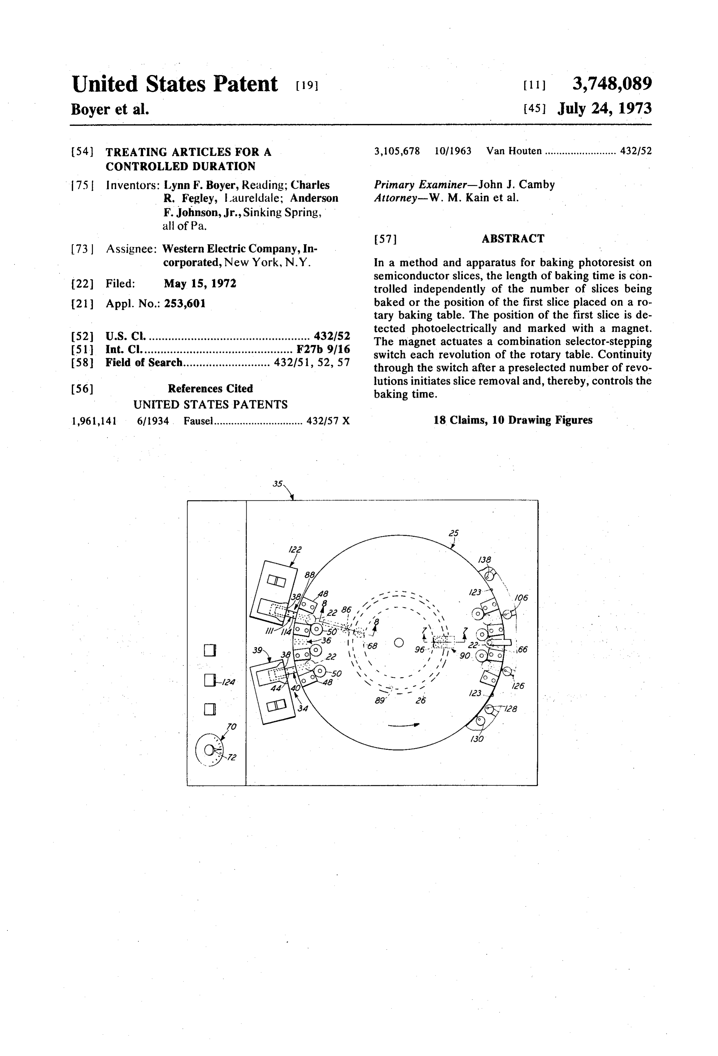
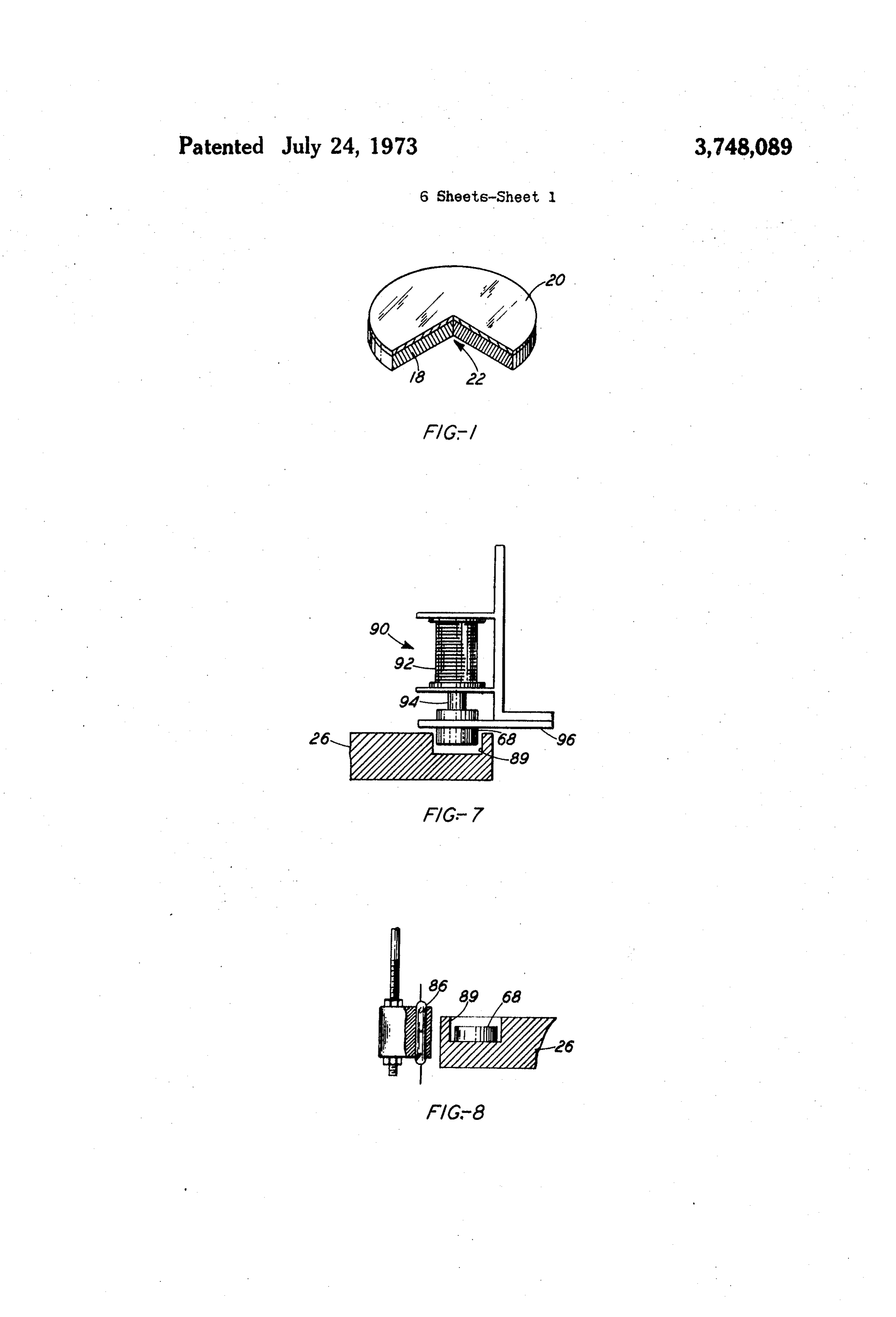
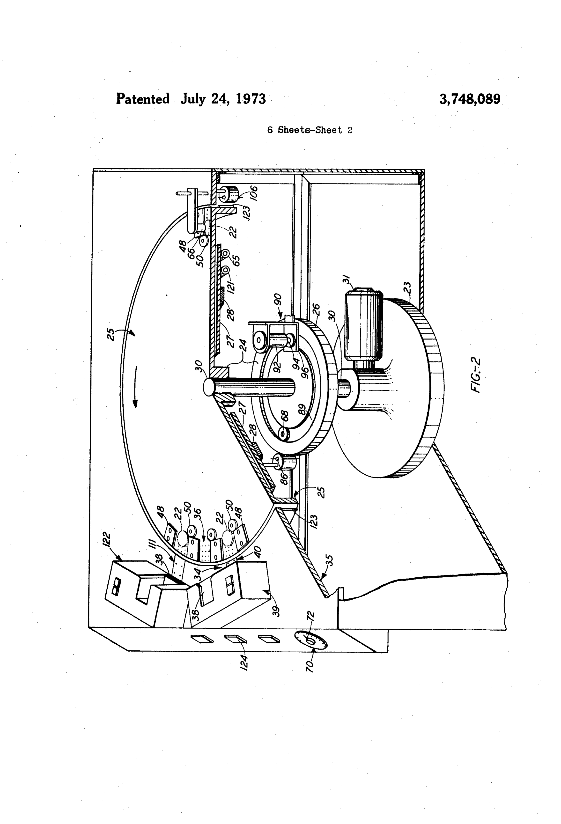
manually unloaded. BRIEF DESCRIPTION OF THE DRAWIN GS Such manual handling of slices is undesirable be cause of potential damage that may be caused by it. The invention can be understood best from the foll Also, this manual handling is costly and manual timer 30 lowing more detailed description taken in conjunction setting is subject to mistakes. It is desirable, therefore, with the accompanying drawings: to automate the loading of slices onto the baking FIG. 1 is an isometric view, partially cut away, of a means, the control of the baking time, and the unload semiconductor slice coated with photoresist; ing of the slices. This is most easily done by making the FIG. 2 is an isometric view, partially cut away, of an baking means rotate and yield the advantage of auto apparatus for baking the photoresist on the semicon matically returning any slices placed on it to the start 35 ductor slices;
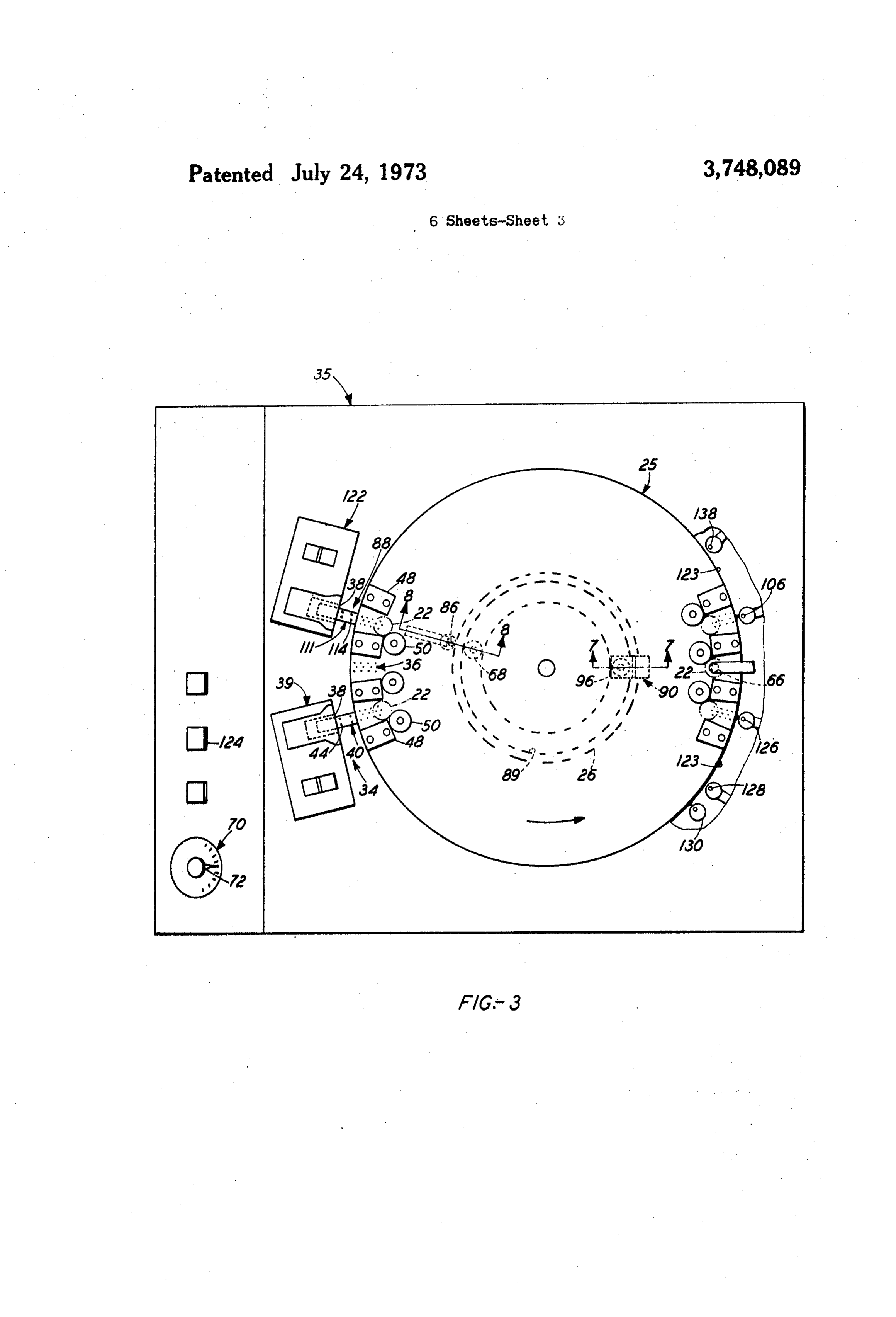
ing point to be removed. . FIG. 3 is a plan view of the apparatus showing how . Some prior art methods control the number of revo some of the parts are arranged around the center of the lutions or length of time by means of a magnet fixed to apparatus;
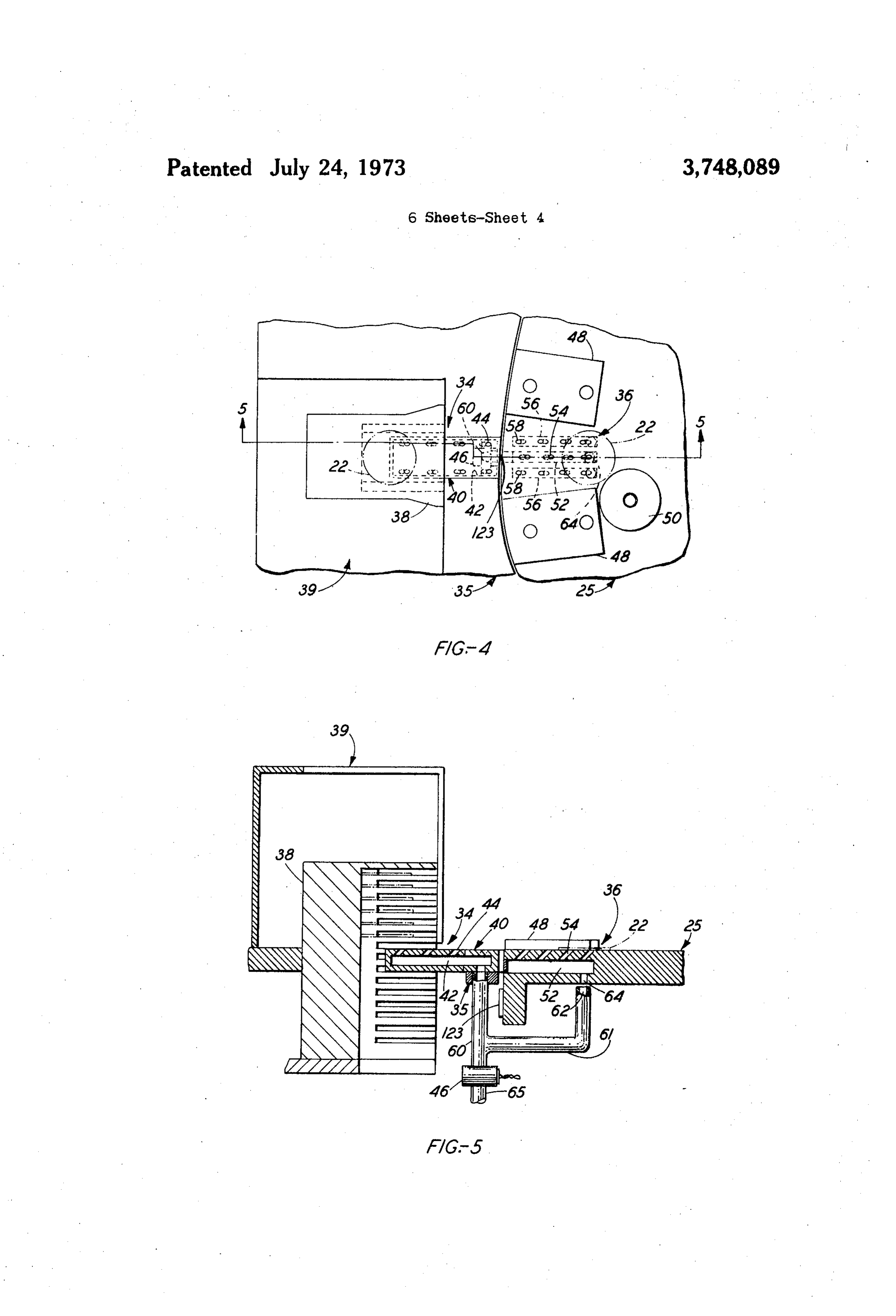
a disc, a sealed contact, and a counter-timer. The mag FIG. 4 is a plan view of a load station and baking po net operates the sealed contact and a counter counts 40 sition showing how the slices are conveyed to their bak during the time interval which a timer permits. How ing position on a rotary table;
ever, where it is possible to rotate a baking means at FIG. 5 is a cross section along line 5-5 of FIG. 4, of constant speed, the length of baking time may be gov the load station and baking position;
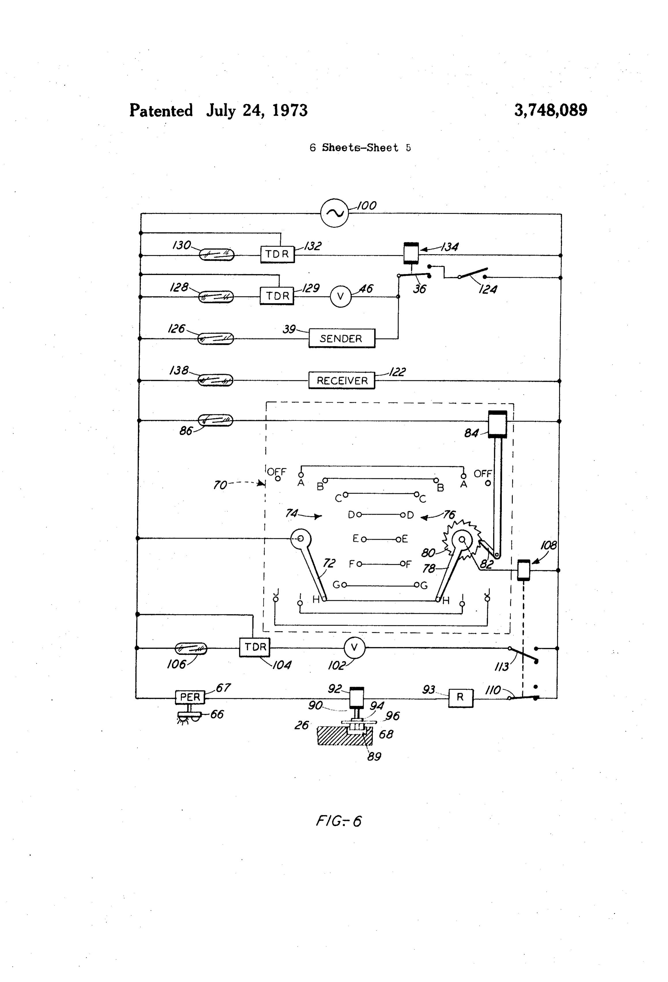
erned by controlling the number revolutions of the bak 45 FIG. 6 is an electrical schematic showing how a selec ing means. This yields the further advantage of elimi tor switch and stepping switch are connected to form nating the timer as such. a combination selector-stepping switch, how a sealed As is well known in the semiconductor and thin film contact operates the stepping switch, and how the com art, the photoresist must be baked to achieve the adher bination operates to remove the slices and the marker ence and toughness necessary to withstand the process 50 .magnet to end the baking; w ing involved in the manufacture of thin film and semi FIG. 7 is a partial cross section, along line 7-7 of conductor devices. The adherence and toughness im FIG.3, showing a marker magnet and magnet holder in prove with length of baking time; so much so, that the elevation, for placing the magnet on and lifting it off a photoresist becomes difficult to remove if baked too rotary table;
long. There is an advantage, therefore, to limiting the FIG. 8 is a partial cross section, along the line 8-8 baking to some predetermined amount which provides 55 of FIG. 3, showing the marker magnet on the table and the best compromise between adherence and ease of an adjacent sealed contact which operates the stepping removal. This advantage is achieved by identifying the switch;
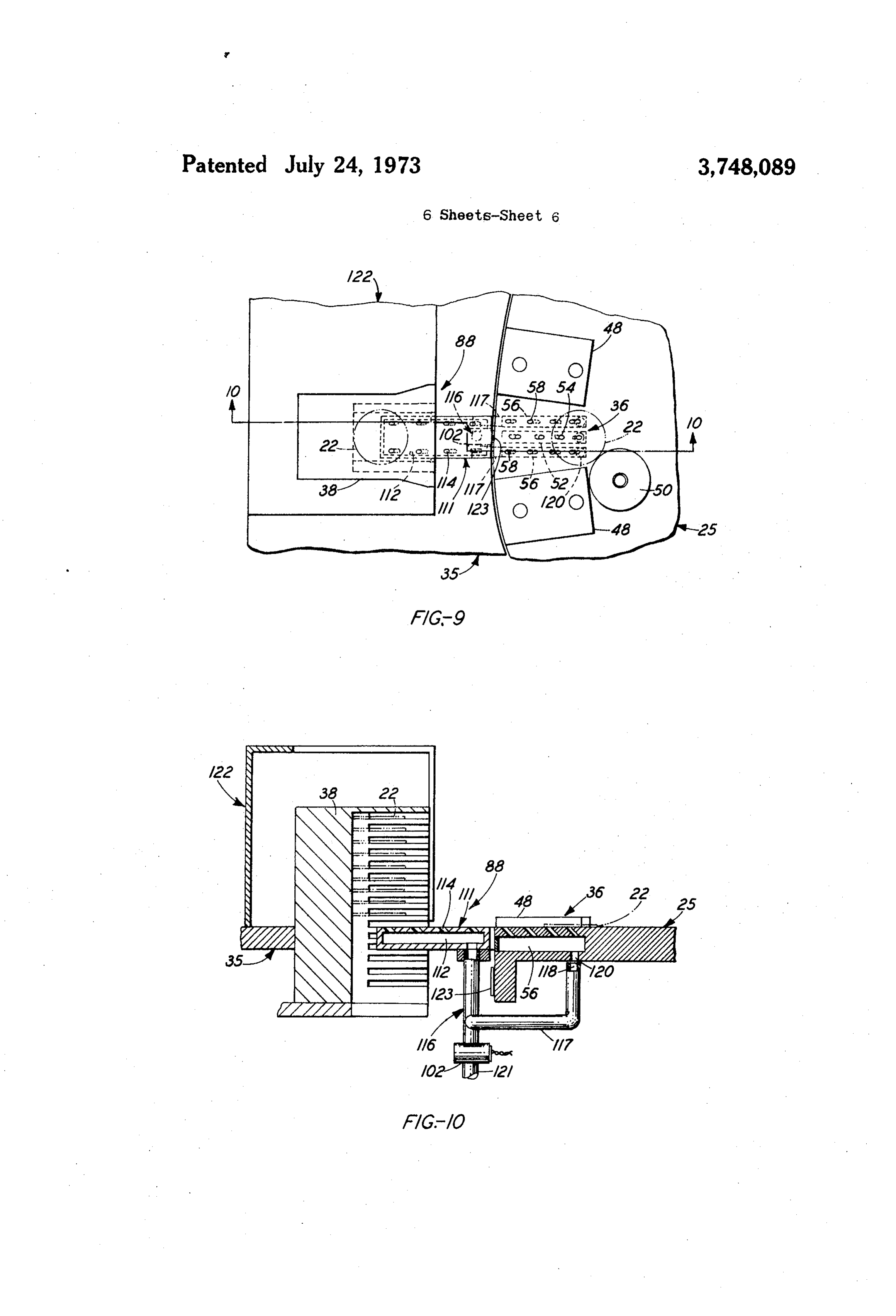
location of the first slice placed on the baking means so FIG. 9 is a plan view of an unload station and baking that the baking time of it and all other slices following 60 position; and it in sequence, may be precisely controlled. FIG. 10 is a cross section of the unload station and baking position along the line 10-10 of FIG. 9.
SUMMARY OF THE INVENTION
DETALED DESCRIPTION
Accordingly, an object of the invention is to provide new and improved methods and apparatus for treating 65 Methods and apparatus embodying the invention will articles for a controlled duration. be described in connection with baking photoresist on With this and other objects in view, the present in semiconductor slices. However, it is to be understood vention contemplates a method for treating articles, the invention may be used for other articles.
Page 9
Referring now to FIG. 1, a silicon slice 18 is coated The location of the first slice 22 and its baking posi with a photoresist 20 to form a coated slice designated tion 36 may be determined by means of a photocell de generally by the numeral 22. The photoresist 20 may be tector 66. The detector 66, refer to FIGS. 2, 3 and 6, that sold by the Eastman Kodak Company under the projects light downward toward the upper level 25 and trade designation"KPR.' receives any light reflected back again. If enough light The photoresist 20 may be baked best with a rotary is reflected back, as when a slice 22 passes beneath the apparatus, refer to FIG. 2, in which a base 23 supports detector 66, the reflected light activates the detector a rotary table 24 having an upper level 25 and a lower 66 which operates a photoelectric relay 67, FIG. 6, and level 26. The upper level 25 is indirectly heated from causes a magnet 68 to be dropped on the lower level 26 below by convection and radiation and its proximity to 10 of the table 24. Thus, the magnet 68 marks the position a plate 27 which is directly heated by a heater 28, e.g., of the first slice 22 above on the upper level 25. a 1,000 watt Chromalox No. A-90 ring heater. In this The total baking time for the photoresist 20 is ob way, the coated slices 22 are heated from the bottom tained by processing the slice 22 through enough bake and the photoresist 20 is baked outward from its con cycles (revolutions of the table 24) to add to the total tact with the slice 18 so that gas bubbles are not 15 baking time desired. Control of the number of revolu trapped in it. The upper level 25 is Teflon coated and tions of the table 24 and thereby, the total baking time is rotated at a constant speed, e.g., one r. p.m. The cons is achieved, preferably, by a switching device in the tant speed provides uniform heating of the upper level form of a combination selector-stepping switch 70. 25 by the plate 27 and permits the number of revolu Referring to FIG. 6, a selector arm 72 of the switch tions to determine the total heating or baking time in 20 70 may be set to contact any one of the plurality of se minutes. For example, 20 revolutions will yield a 20 lector contacts 74; e.g., a contact 74h as in FIG. 6, minute total baking time. which will yield the correct number of revolutions as Both the upper level 25 and lower level 26 are fixed determined from the desired baking time and known to a vertical shaft 30 so that they rotate together as a speed of the table 24. The contacts 74a to 74.j are con unit, i.e., the table 24, when the shaft 30 is revolved by 25 nected in parallel to like stepping contacts 76a to 76.j, a drive motor 31. i.e., the selector contact 74a is connected to the step Referring now to FIGS. 3, 4 and 5, there is shown a ping contact 76a, the selector contact 74b is connected load station 34, which is part of a stationary table 35, to the stepping contact 76b, etc.
for loading photoresist coated slices 22 into baking po A stepping arm 78 is fixed to a ratchet wheel 80 or sitions 36 on the upper level 25 of the table 24. The 30 the equivalent, and a pawl 82, actuated by a solenoid slices 22 are handled in carriers 38 and one of these 84, moves the ratchet wheel 80 and, thereby, the step carriers, having the slices to be baked, is inserted in the ping arm 78. Each time the solenoid 84 is energized the vertical indexing mechanism of a load station sender, arm 78 steps from one contact 76 to another. designated generally by the numeral 39, of the type The magnet 68, refer to FIG. 8, which is placed on sold for that purpose by the Industrial Modular Systems 35 the lower level 26 of the table 24 to mark the position Corporation. The slices 22 are evenly spaced in the car of the first slice 22 may be a disc or ring of permanent rier 38 and are removed therefrom by an air conveyor magnet material, preferably a ring of Alnico V or the 40 which includes plenum 42, nozzles 44 facing toward like about 6 inch O.D. X % inch I.D. x 4 inch thick, the center of rotation, and a solenoid valve 46. magnetized axially.
There are a plurality of baking positions 36, e.g., 40 When the lower level 26 rotates and the magnet 68 twenty-five, only some of which are shown. The baking is resting on it, the magnet passes a sealed contact 86 positions 36 include guides 48; stops 50; and three ple which is sensitive to the flux of the magnet. The sealed nums, one plenum 52 having nozzles 54 directed to contact 86 is a hermetically-sealed, normally-open, ward the center of rotation and two plenums 56 having 45 flux-sensitive switch, sometimes called a dry reed nozzles 58 directed away from the center of rotation. switch in the art, which is closed by the magnetic flux Air is admitted to the load station plenum 42 and when the magnet 68 is adjacent to it. Switch closure oc baking position plenum 52 by the solenoid valve 46 via curs which the first slice 22 is above the sealed contact connections 60 and 61, orifice 62 and port 64; and it 86, because the first slice 22 is on the upper level 25 of flows out through the nozzles 44 and 54, respectively. 50 the table 24 above the marker magnet 68. Since the This air is preheated by passage through tubing 65, at contact 86 is positioned along the same radius as an un tached to the plate 27, refer to FIG. 2, so that it will not load station 88, refer to FIG. 3, each closure of the con cool the upper level 25. Since the nozzles 44 and 54 are tact 86 signals both: that one revolution of the table 24, directed toward the center of rotation, the slice 22 is and therefore one bake cycle, has been completed; and conveyed by air from the sender carrier 38 to the bak 55 that the first slice 22 is at the proper location to be con ing position 36 where it lodges against the stop 50. The veyed from its baking position 36 into the carrier 38 at stop 50 is off center, as shown, in order to prevent the unload station 88.
bouncing of the slice 22. Further understanding of this The magnet 68 is picked up from and dropped into may be had from L. F. Boyer and A. F. Johnson, Jr. a groove 89 in the lower level 25 of the table 24 by a "Air Bearing Stop," technical digest, Western Electric magnet holder 90. The magnet holder 90, refer to FIG. Company, Issue 20, October 1970, pages 13 and 14. 60 7, includes a solenoid 92 having a vertically moving Sequential loading of the slices 22 onto the upper plunger 94, and a nonmagnetic separator plate 96. The level 25 of the table 24 may start at any baking position holder 90 is in radial alignment with the detector 66, 36. However, the baking position 36, into which the refer to FIG. 3, and its solenoid 92 lifts the plunger 94 first slice 22 is loaded, must be identified so taht the 65 from or drops it onto the nonmagnetic separator plate start of baking and the number of revolutions of the 96. The plunger, 94 is magnetic but not permanently table 24, and thereby the total baking time, may be magnetizable. When the plunger 94 is on the plate 96, controlled. the magnet 68 resting in the annular groove 89 of the
Page 10
lower level 26 of the table 24 will attract itself to the The valve 102, refer to FIGS. 9 and 10, admits pre plunger and lift itself a short distance up against the un heated air both to: an unload station conveyor 111, derside of the nonmagnetic separator plate 96. Thus, having a plenum 112 with nozzles 114 directed toward the magnet 68 will remain suspended free of the lower the carrier 38, through a connection 116; and the two level 26 as long as the solenoid 92 remains unener plenums 56 in the upper level 25 through two connec gized. When the solenoid 92 is energized, such as when tions 117, two orifices 118 and two entrance ports 120. the photocell detector 66 detects a slice 22 and actu The air is preheated by passage through tubing 121 at ates the associated electrical circuit, the solenoid lifts tached to the underside of the plate 27. Each orifice the plunger 94 far enough to make the space between 118 aligns with its respective port 120 at the same time the end of the plunger and the separator plate 96 so O that the baking position 36 aligns with the unload sta large that the force of attraction between the magnet tion 88. Consequently, air flowing out the nozzles 58 68 and the plunger becomes too weak to support the and 114 conveys the slice 22 from the baking position magnet. Consequently, the magnet 68 drops into the 36 to the carrier 38 which is indexed vertically by the groove 89 on the lower level 26 of the table 24. index mechanism of an unload station receiver, gener For best results, solenoid 92 should be supplied with 15 ally designated by the numeral 122, identical to the the current connected so that the magnetic field of the sender 39.
solenoid is in the opposite direction to that of the mag A plurality of magnets 123, refer to FIG. 3, are fixed net 68. This may be accomplished with a rectifier 93. to the upper level 25, one at each baking position 36 The magnet 68 may be placed at any position in the approximately on its centerline. The magnets 123 may groove 89 around the lower level 26 by energizing and 20 be 4 inch diameter by 1 inch long rod magnets such as de-energizing the solenoid 92 at the appropriate time. type CR-400-1 sold by Indiana General Corporation. It is to be noted that the magnet 68 could be placed Each magnet 123 closes the sealed contact 106 as each on and removed from the upper level 25. However, the baking position 36 aligns with the unload. station 88. use of the lower level 26 removes the contact 86 and The air valve 102 is made to operate at the precise time magnet holder 90 from the heat above the upper level 25 that the orifices 118 are aligned with the ports 120 and 25 and, thereby, increases the life of these components. the baking position 36 is aligned with the unload station Although the foregoing method of picking up the 88, by adjusting the time delay relay 104. Thus, the magnet 68 is preferred, there are other well known slices 22 are conveyed one after the other, i.e., sequen ways to pick it up. For example, a vacuum nozzle may 30 tially, from the baking positions 36. w be substituted for the plunger 94 and the vacuum con Although sealed contacts, such as contact 106, oper trolled by a solenoid valve to pickup or drop the mag ated by the rod magnets 123 are preferred because no net 68 as desired. In addition, a disc with a reflective. rubbing surfaces are involved, the sealed contacts may surface may be substituted for the magnet. 68 and a be replaced by microswitches having followers bearing photocell detector substituted for the sealed contact 86 against the upper level 25 of the table 24 and the mag to achieve results similar to the much less costly sealed 35 nets may be replaced by rods or the equivalent made contact and magnet. of material other than magnet material. As is known in In any case, when the presence of the first slice 22 the art, the rods will act as cam lobes which will operate loaded on the upper level 25 of the table 24 is detected, the microswitches. Thus, cam lobes and microswitches the magnet 68, or its equivalent, is dropped on the will replace magnets and sealed contacts but, of course, lower level 26 at the same angular position as the slice, 40 are subject to much more wear. refer to FIG. 3, because the holder 90 is aligned along OPERATION the same radius as the detector 66. The magnet 68 re mains in this position marking or identifying the loca The operation of the baking apparatus may be under tion above, of the slice 22 on the upper level 25. stood best by: referring to FIGS. 2, 3 and 6; assuming The stepping arm 78 of the switch 70 is connected to 45 that the speed of rotation of the table 24 is 1 rpm; and one side of a voltage source 100, refer to FIG. 6, and assuming that the photoresist 20 must be baked for five the selector arm 72 is connected to the other side minutes. The schematic diagram of FIG. 6 does not through: a solenoid valve 102, a time delay relay 104, show the circuits for the drive motor 31 or heater 28 and a sealed contact 106; and a relay 108. When the 50 because these are well known in the art. selector arm 72 is set to contact 74h, as in FIG. 6, and The arm 72 of the selector-stepping switch 70 is set the table 24 revolved eight times to cause the magnet to contact 74e, the fifth contact from OFF; the heater 68 to close the sealed contact 86 eight times, the step 28 and motor 31 are energized; and the upper level 25 ping arm 78 is on contact 76h, relay 108 is actuated, of the table 24 is allowed to rotate in the direction of normally open contacts 113 are closed, and the sole 55 the arrow until thermal equilibrium is reached. noid valve 102 is in condition to be operated by closure When equilibrium is reached, a sender switch 124 is of the sealed contact 106. The contact 106 may be lo closed so that the sender 39 and solenoid valve. 46 are cated any whole number of baking positions 36 away connected to the voltage source 100 through sealed from the center line of the unload station 88. Also, contacts 126 and 128, respectively. The contact 128 is when arms 72 and 78 are on contacts 74h and 76h, 60 closed by one of the magnets 123 and operates the respectively, continuity ensues and the relay 108 opens valve 46 admitting air to the load station 34 and baking its normally-closed contacts 110 to disconnect the position 36. This removes the first slice 22 from the magnet solenoid 92 from the source of voltage. This sender carrier 38. Precise timing so that the valve 46 drops, the plunger 94 onto the separator plate 96 so that operates when the load station 34 and baking position the magnet 68 attaches itself to the underside of the 65 36 are aligned, is achieved by adjustment of a time. plate. Thus, the holder 90 removes the magnet 68 in re delay. relay 129.
sponse... to continuity through the selector-stepping Contact 126 closes, following closure of contact. 128, switch,70. and indexes the sender 39 mechanism one step down
Page 11
ward. This lowers the next slice 22 into position to be stepping switch 70 is reset so that the next lot of slices conveyed or sent into the next baking position 36. The may be baked.
closure of contact 126 occurs after closure of contact It is to be noted that the slices may be baked starting 128 because the sealed contact 126 is located one and with the table 24 in any position and a wide range in one half baking positions 36 beyond the contact 128 in baking times may be had by proper choice of the speed the direction of rotation (see FIG. 3). However, if the of the table and the number of contacts for the selec switch 124 is closed when the table 24 rotation is such tor-stepping switch 70.
that two of the magnets 123 are between the sealed Thus, a method and apparatus for carrying out the contacts 128 and 126, the carrier 38 in the sender 39 method have been disclosed for treating articles for a may index downward and break a slice 22 before air is O controlled duration independently of the number of ar admitted to the sender conveyor 40. This may be pre ticles or where the first one is placed on the apparatus. vented by a sealed contact 130, time delay relay 132 While specific embodiments have been described in and a relay 134 having contacts 136. When switch 124 the foregoing specification to illustrate the invention, it is closed, the contacts 136 of relay 134 are open until will be understood that the invention is not limited to the sealed contact 130 is closed by a magnet 123. This 15 these embodiments. Various changes and modifica sealed contact is located adjacent the upper level 25 a tions may be made without departing from the spirit few degrees in advance of contact 128, e.g., about 5 and scope of the invention.
(or any even number of baking positions plus 5). Clo What is claimed is:
sure of contact 130 energizes the time delay relay 132 1. A method of treating articles, wherein the duration which, in turn, energizes the relay 134 for about 1.4 20 of treatment is controlled by a marker, which com seconds. During this interval the orientation of the prises the steps of:
magnets 123 with respect to the sealed contacts 128 a. placing a series of the articles on an endless con and 126 is such that they will be operated in that order, veyor for treatment;
i.e., the proper sequence. Thus, the slices 22 are se b. detecting the location of the first article of the se quentially removed from the sender carrier 38 and 25 ries of articles placed on the conveyor; placed in adjacent baking positions 36, by sequentially c. positioning the marker on the conveyor in re operating the sealed contact 128 first and the contact sponse to the detection of the location to identify 126 second. Baking then takes place at the temperature such location;
of the upper level 25. d. actuating a switching device by means of the The position 36 of the first slice 22 loaded on the 30 marker to count the number of cycles completed upper level 25 is detected by light reflected from the by the endless conveyor and to establish continuity slice back into the photocell detector 66, which is a through the switching device when a predeter part of a photoelectric relay 67. Reflected light seen by mined number of cycles has been completed; and the photocell detector 66 causes the relay 67 to ener 35 e. removing the marker and the articles from the con gize the magnet-holder solenoid 92 and the plunger94 veyor to terminate the treatment, in response to the to be lifted. The magnet 68, as a consequence, drops to continuity and beginning with the first article as the lower level 26 and marks the position of the first identified by the marker.
slice 22. 2. The method of claim 1 wherein the marker is The first slice 22 will have been carried through es dropped on the conveyor.
sentially one revolution and one baking cycle when it 40 3. The method of claim 2 wherein the marker is mag arrives at the unload station 88. The sealed contact 86, netic.
positioned adjacent the lower level 26 in line with the 4. The method of claim 1 wherein there is only one station 88, is closed by the marker magnet 68 and ener article in the series.
gizes the stepping-switch solenoid 84 to move the arm 45 5. The method of claim 1 wherein the switching de 78 to the first contact 76a. This is repeated as the table vice is a combination selector-stepping switch. 24 rotates until, at the end of five minutes, the arm 78 6. The method of claim 5 wherein the articles are establishes electrical continuity from one side of the semiconductor slices coated with photoresist and the voltage source 100 through the relay 108, the arm 78 treatment is baking the photoresist.
itself, the contact 76e, the contact 74e and the selector 7. The method of claim 6 wherein the endless con switch arm 72 to the other side of the source. This ener 50 veyor is a rotating table. - gizes the relay 108 which opens the normally closed 8. The method of claim 7 wherein the magnetic contacts 110, de-energizes the magnet-holder solenoid marker operates a sealed contact to actuate the switch 92, drops the plunger 94 and lifts;the magnet 68 from ing device.
the lower level 26. At the same time, the relay 108 re 9. A method of baking photoresist on semiconductor sets photoelectric relay 67 and closes its normally open 55 slices, wherein the length of baking time is controlled contacts 113 to connect the unload solenoid valve 102 by a magnetic marker, which comprises of steps of: to the voltage source. Thus, each time one of the mag a. positioning a selector portion of a selector nets 123 closes the sealed contact 106, the valve 102 stepping switch to a preselected contact represent admits air to the baking position 36 and the unload sta 60 ing the number of revolutions of a rotary table tion 88. This conveys the first slice 22 into the receiver which will yield the desired length of baking time; carrier 38 and ends the baking of the photoresist 20 for b. rotating the table to sequentially receive a plurality that slice. Shortly thereafter, one of the magnets 123 of slices from a carrier;
closes a sealed contact 138, refer to FIG. 3, which ener c. conveying the slices sequentially from the carrier gizes the indexing mechanism of the receiver 122 once 65 into each of a plurality of slices positions on the ro and raises the receiver carrier 38 one step into position tary table;
to receive the next slice 22. This is repeated until all d. heating the table to bake the photoresist on the slices are removed in sequence. Then, the selector slices;
Page 12
e. detecting the position of the first slice; b. a rotary table supported by the base and having f. dropping a magnetic marker on the rotary table in baking positions for baking the photoresist on the alignment with the first slice to mark its position; slices;
g. positioning a magnetic flux sensitive switch adja c. a loading station for loading the slices sequentially cent the rotary table, the switch being aligned with 5 into each baking position;
a carrier at an unload station and capable of oper d. a photocell detector to determine the baking posi ating the stepping portion of the selector-stepping tion of the first slice;
e. a combination selector-stepping switch for select switch; ing the number of revolutions through which the h. actuating the flux-sensitive switch by means of the table is to be rotated, and for counting the revolu magnetic marker to operate the stepping portion of 10 tions of the table to control the baking time; the selector-stepping switch each revolution of the f. a marker, positionable on the table to mark the lo table until continuity is established through the cation of the first slice;
preselected contact; g. a switch, operated by the marker once each revolu i. lifting the magnetic marker from the table in re 15 tion, to actuate the stepping portion of the selector sponse to the continuity; and stepping switch and count the revolutions of the ta j. removing the slices from their positions on the table ble;
in response to the continuity, starting with the first h, a marker holder, aligned with and responsive to slice, to terminate the baking of the photoresist on the photocell detector for positioning the marker each slice at the end of the preselected length of 20 on the table in line with the first slice and respon time.
sive to the selector-stepping switch for removing the marker from the table after the preselected 10. An apparatus for treating articles, which com number of revolutions;
prises: i. an unloading station adjacent the table to receive a. means for transporting the articles through a pre the baked slices; and determined number of treating cycles; 25 j. means for removing the slices sequentially from the b. means for loading the articles sequentially on the table, beginning with the first slice, and conveying transporting means; the slices into the unloading station in response to c. means for detecting the first article loaded on the the selector-stepping switch, thereby ending the transporting means; slice baking.
d. means for marking the location of the first article; so ductorAnslices, 18. apparatus for baking photoresist on semicon which comprises:
e. means, responsive to the detecting means, for plac a. a base;
ing the marking means on the transporting means b. a rotary table supported by the base for baking the at the beginning of treatment, to mark the location photoresist on the slices, the table having a heated of the first article, and for removing the marking upper level and a lower level; means at the end of treatment; 35 c. a loading station adjacent the upper level of the f, means, responsive to the marking means, for con table for loading slices sequentially into a baking trolling the number of treating cycles the first arti position for each slice on the table; cle makes and thereby the total duration of the d. a photocell detector adjacent the upper level of the treatment of the articles; and table to determine the baking position of the first g, means, responsive to the cycle controlling means, 40 slice; V for removing the articles sequentially from the e. a combination selector-stepping switch for select transporting means beginning with the first article ing the number of revolutions through which the marked by the magnet. - table is to be rotated and counting the revolutions 11. An apparatus, as recited in claim 10, wherein the to control the baking time, continuity therethrough means for marking the location of the first article com- 45 being established when the preselected number of prises a permanent magnet positioned in relation to the revolutions have been counted; first article. f. a magnet, positionable on the lower level of the ta ble, to mark the location of the first slice;
12. An apparatus, as recited on claim 11, wherein the g. a flux-sensitive switch, adjacent the lower level of transporting means comprises a rotary table. the table, the switch being closed by the flux of the 13. An apparatus, as recited in claim 12, wherein the 50 magnet once each evolution of the table to actuate means for detecting the first slice comprises a photocell the stepping portion of the selector-stepping switch and a photoelectric relay. to count the number of revolutions; 14. An apparatus, as recited in claim 13, wherein the h. a magnet holder adjacent the lower level of the means responsive to the detecting means comprises a table and aligned with the photocell detector, the solenoid having a plunger which may be raised or low 55 holder being responsive to the photocell detector ered to position the marking means in relation to the for depositing the magnet on the lower level of the first article. table, and responsive to continuity through the 15. An apparatus, as recited in claim 14, wherein the combination selector-stepping switch for removing means responsive to the marking means comprises a the magnet from the table after the preselected sealed contact and combination selector-stepping 60 i. an number of revolutions;
switch.
unload station adjacent the upper level of the table to receive the baked slices; and 16. An apparatus, as recited in claim 15, wherein the j. means for removing the slices sequentially from the articles are photoresist coated semiconductor slices table, beginning with the first slice, and conveying and the treatment comprises baking the photoresist. 65 the slices into the unloading station in response to 17. An apparatus for baking photoresist on semicon continuity through the selector-stepping switch, ductor slices, which comprises: thereby ending skthe slicek baking.
a. a base;
Provenance
- Collection
- Cited prior art
- Original PDF
- patentimages.storage.googleapis.com →
- Filed
- 1972-05-15
- Pages
- 12
- Method
- pdftotext (the PDF's own text layer) + pdftoppm 300dpi page scans
- Source
- Google Patents bibliographic record
- Granted
- 1973-07-24
- Inventors
- A Johnson; L Boyer; C Fegley; Western Electric Co Inc
- Transcribed from
- patentimages.storage.googleapis.com →