patent · US5177388
Tandem type alternator
5 January 1993
Page 1 — bibliographic record
United States Patent (19) 11) Patent Number: 5,177,388 Hotta et al. 45) Date of Patent: Jan. 5, 1993 (54) TANDEM TYPE ALTERNATOR FOREIGN PATENT DOCUMENTS 75) Inventors: Toshiaki Hotta, Chiryu; Keiichiro 55-163784 11/1980 Japan . Banzai, Toyota, both of Japan 61-58869 4/1986 Japan .
73) Assignee: Nippondenso Co., Ltd., Kariya, Japan 61-162262 10/1986 Japan.
(21) Appl. No.: 702,908 Primary Examiner-Steven L. Stephan Assistant Examiner-Clayton E. LaBalle 22) Filed: May 21, 1991 Attorney, Agent, or Firm-Cushman, Darby & Cushman 30 Foreign Application Priority Data 57 ABSTRACT May 23, 1990 JP Japan .................................. 2-33488 A tanden type alternator comprises a rotor rotatably 51 Int. Cl. ....................... H02K 16/00; HO2K 9/OO; supported inside a housing and having rotor cores hav HO2K9/06; HO2K 9/02 ing magnetic poles formed on outer peripheral portions 52 U.S. Cl. ...................................... 310/114; 31 O/58; of the rotor cores, respectively, and a plurality of stators 30/62 arranged on an inside wall of the housing and in tandem in the direction of the axis of rotation of the rotor and 58) Field of Search ....................... 310/58, 62, 63, 59, having tooth-shaped stator cores which are positioned 310/68 D, 112, 114, 18, 126, 263; 322/29, 32, to be opposite to the magnetic poles of the rotor cores
and on which multi-phase windings are wound, respec 56) References Cited tively. The stators have respectively the multi-phase
ings are shifted from each other in the direction of the 1,692.371 1/928. Froesch ................................. 310/59 axis of rotation of the rotor. The housing has ventilation 2.006,172 6/1935 Kappauf ...... 31 O/12 window portions formed between and near the plurality 2,454,120 l/1948 Atwell et al. ......................... 310/59 of stators which provide communication between the 3.459,980 8/1969 Coroller ....... ... 310/14 3,535,572 10/1970 DeRugeris ... 30/68 interior and exterior of the housing, so that ventilation 3,610,979 10/1971 Thomas ............................... 3O/263 resistance within the housing is reduced and the cooling 4,755,698 7/1988 Frister et al. ......................... 31 O/5 effect is increased.
4,780,659 10/1988 Bansal et al. .......................... 322/58 4,954,734 9/1990 Iguchi et al. ..................... 30/68 D 7 Claims, 4 Drawing Sheets
As YAY
Page 2
Drawing sheet — no readable text.
Page 3
Drawing sheet — no readable text.
Page 4
Drawing sheet — no readable text.
Page 5
Drawing sheet — no readable text.
Page 6
the stators, and hence it is hard for the multi-phase
TANDEM TYPE ALTERNATOR windings of both stators to come into contact with each other. As a result, spaces extending in the rotational
BACKGROUND OF THE INVENTION direction are formed between the stators. The present invention relates to a tandem type alter Further, since the ventilation windows are disposed nator for a vehicle. in the portions of the housing outside the stators and An alternator for a vehicle includes a compact tan near the spaces formed between the stators, the spaces dem type alternator having a plurality of sets of stators formed between the stators and the exterior of the hous and rotors in order to meet an increasing power demand 10 ing communicate each other.
and to improve mountability on a vehicle. By virtue of this structure, when the rotor is driven to In the tandem type alternator for a vehicle, a plurality rotate, an air flow generated inside and outside the of rotors are arranged in tandem along a rotational shaft housing by the vanes disposed at various portions of the and stators are arranged outside the rotors to surround alternator easily moves inside and outside the housing the rotors, and the rotors and the stators are accommo passing through the ventilation windows, thereby cool 15 ing the interior of the housing, dated in a housing.
Ventilation holes for passing therethrough external According to the present invention, since intermedi air are formed in the housing at the axially opposite end ate portions between the stators, which are arranged in walls thereof. As the rotors rotate, an air flow from the tandern in the housing, are cooled, it is difficult to re ventilation holes in one end wall to those in the other duce the electric generating capability, and a suffi end wall is generated by vanes attached to the rotors 20 ciently large electric generating capability can be ob and by vanes mounted on the rotational shaft outside tained with an alternator for a vehicle having a limited the housing so that cooling of the interior of the housing size in itself.
may be attained.
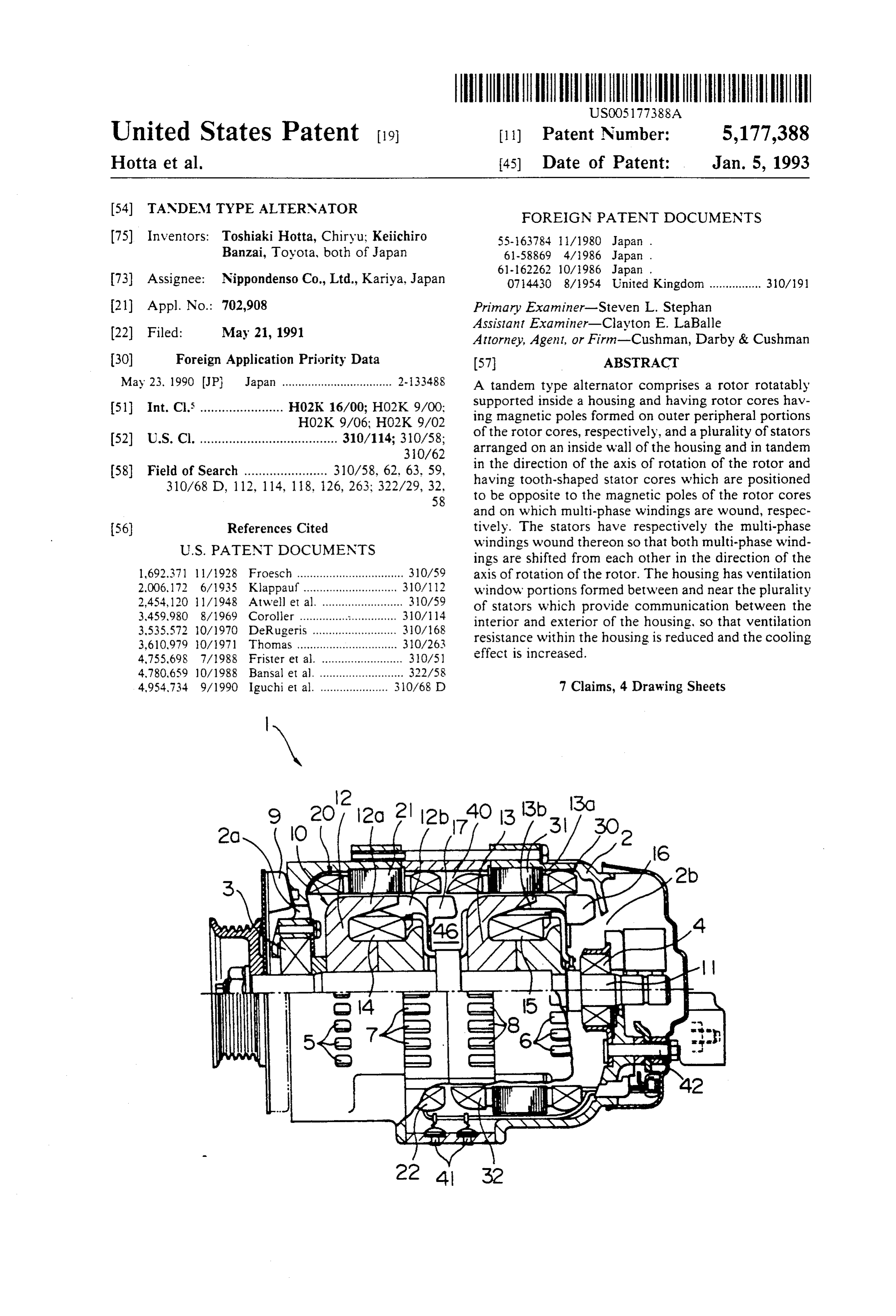
However, in the tandern type alternator for a vehicle, BRIEF DESCRIPTION OF THE DRAWINGS since the plurality of sets of stators and rotors are ar 25 FIG. 1 is a sectional drawing showing an alternator in ranged axially in tandem, axial ventilation resistance is accordance with one embodiment of the present inven increased and it is difficult to have sufficient air flow tion.
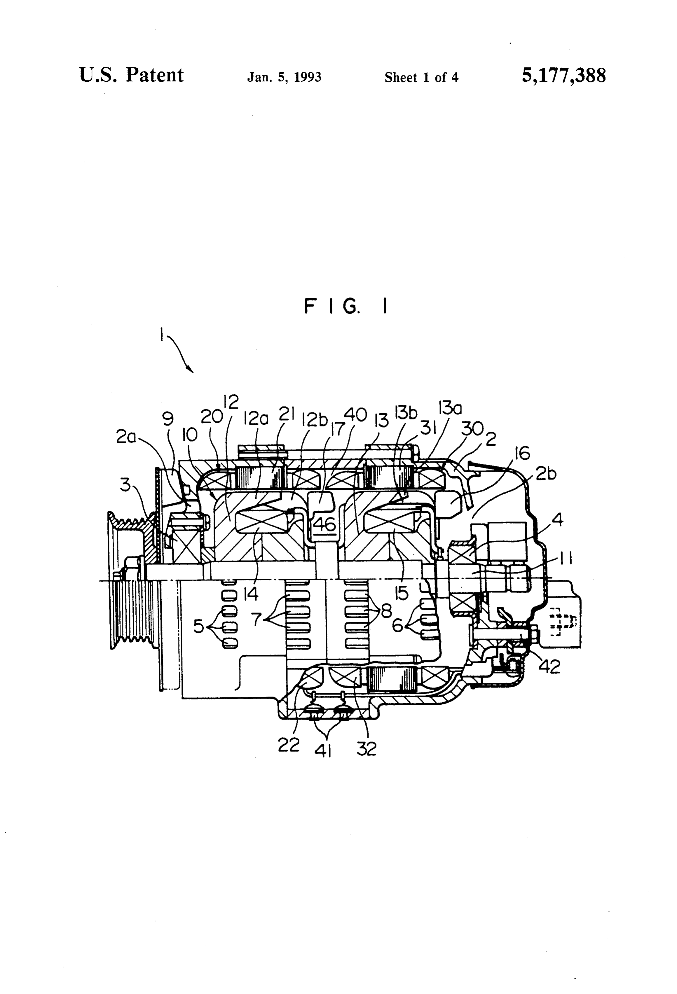
produced. Further, since the tandem type is intended to FIG. 2 is a development drawing showing a develop attain miniaturization, it is impossible to provide a suffi ment of the stators of the alternator in accordance with cient gap between stator windings wound on adjacent the embodiment of the present invention.
StatOS.
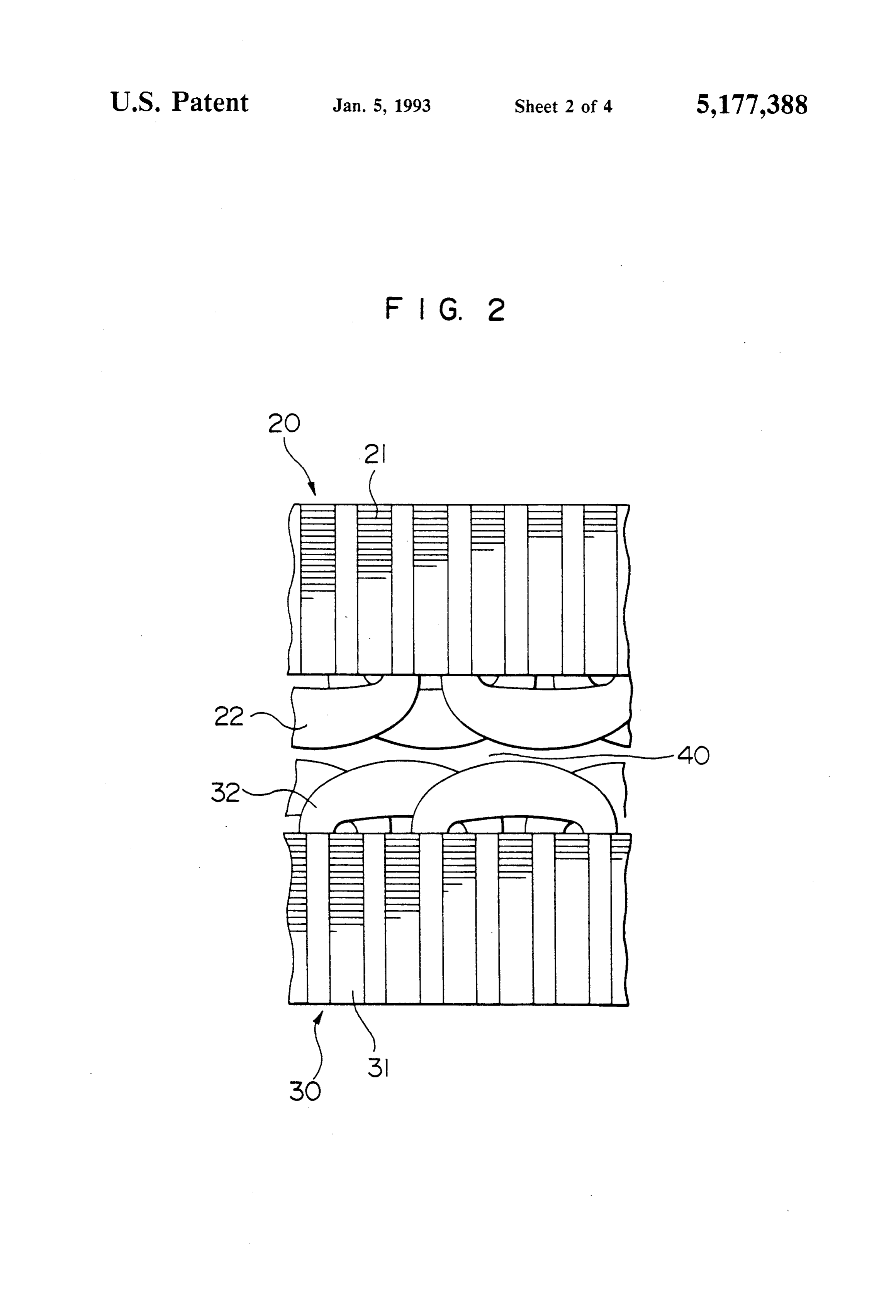
As a result, it becomes difficult to sufficiently dissi FIG. 3 is a circuit diagram showing a power supply pate heat generated in the stator windings within the circuit dance for a vehicle which uses the alternator in accor with the embodiment of the present invention.
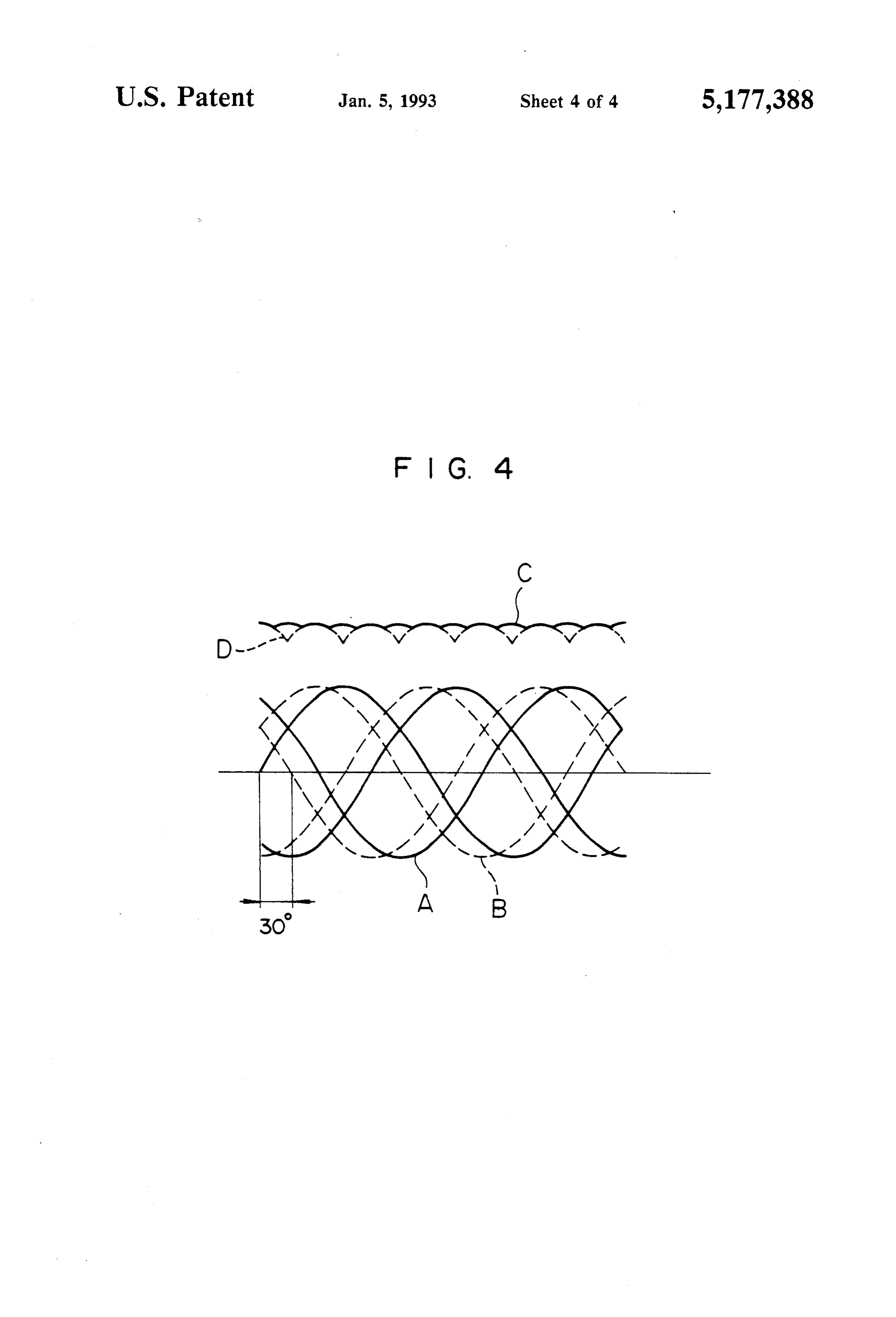
housing to the outside of the housing. Particularly, FIG. 4 is a waveform diagram showing an output during the summer season, for example when atmo 35 voltage waveform of the alternator in accordance with spheric temperature is high, heat is apt to stay within the housing, so that it becomes difficult to achieve suffi. the embodiment of the present invention. cient power generating capability in spite of the circum DESCRIPTION OF THE PREFERRED stances where particularly high power consumption is EMBODIMENT needed. 40
The alternator for a vehicle according to the present
SUMMARY OF THE INVENTION invention will be explained with reference to an em It is an object of the present invention to improve bodiment of the present invention.
cooling performance of a tandem type alternator for a A tandem type alternator 1 of this embodiment vehicle without causing its size to be increased. 45 shown in FIG. has a rotor 10 rotatably supported The present invention provides an alternator which within a substantially cylindrical housing 2 by bearings comprises a rotor rotatably supported in a housing and 3 and 4 mounted in the housing 2 and two substantially having a plurality of magnetic poles disposed on outer cylindrical stators 20 and 30 arranged outside the rotor peripheries thereof, and a plurality of stators arranged 10 surrounding it.
in tandem axially of the rotor in the housing which 50 In the left and right end walls of the housing 2, venti stators have multi-phase windings and tooth-shaped lation openings 2a and 2b for providing communication cores positioned to be opposite to the magnetic poles of between the interior and the exterior of the housing 2 the rotors, respectively. The multi-phase windings are formed, and two hole trains 5 and 6, each of which wound on the stators, respectively, are staggered with hole trains includes a plurality of ventilation holes, are respect to each other in the rotational direction of the 55 provided in a cylindrical side wall of the housing 2 to rotor. Further, ventilation windows for communicating make the rotor 10 intervene between the positions of the the interior and the exterior of the housing are formed two hole trains.
in the housing between the stators. The rotor 10 comprises two rotor cores 12 and 13 In the present invention, the multi-phase windings of having a rotational shaft 11, which is driven by an en the stators arranged in tandem axially of the rotor are 60 gine through a belt (not shown), fitted therein and rotor staggered with respect to each other in the rotational coils 14 and 15, which function as field coils, wound on direction of the rotor. Accordingly, where the stators the two rotor cores 12 and 13, respectively. Six pairs of are arranged in the housing at the same space interval as positive and negative claw magnetic poles 12a, 12b; 13a that of the prior art, the outermost peripheral portions and 13b formed integrally with each of the rotor cores of the multi-phase windings wound on the tooth-shaped 65 12 and 13 are disposed on the outer periphery of each of core of one of the stators are staggered in the rotational the rotor cores 12 and 13 so that positive claw magnetic direction with respect to the outermost peripheral por poles and negative claw magnetic poles are arranged tions of the multi-phase windings of an adjacent one of alternately on the outer periphery of the rotor 10.
Page 7
The rotor cores 12 and 13 are arranged to have paral terminal voltage of the vehicle battery 43 to maintain lel displacement with each other in the direction of the the terminal voltage of the vehicle battery 43 at a con rotational shaft 11 so that the magnetic poles 12a and stant value.
the magnetic poles 13a, and the magnetic poles 12b and As the rotor 10 is driven by the engine when the the magnetic poles 13b are oriented in the same radial 5 engine has started rotation, the alternator 1 generates direction, respectively. .- electric power in accordance with the vehicle load 44. An inclined flow fan 16 for producing an air flow is Since the output voltage of the stator coil 32 has a provided at a right end portion of the rotor core 13 of phase difference of 30 degrees in electrical angle as the rotor 10. As the rotor 10 is rotated, an air flow from compared with that of the stator coil 22, the output the right to the left in the direction of the rotational 10 voltage waveforms of the stator coil 22 and the stator shaft 11 is produced to pass through the space between coil 32 become as shown by a solid line A and a broken the magnetic poles 13a and 13b of the rotor core 13. line B in FIG. 4, respectively, and, after the output A centrifugal fan 17 is disposed at the right end por voltages thereof have been subjected to three-phase tion of the rotor core 12. full-wave rectification through the rectifiers 41 and 42, On the other hand, the stators 20 and 30 respectively 15 respectively, a resultant combination of the rectified have substantially cylindrical stator cores 21 and 31 output voltages has a waveform as shown by a solid line which have been formed by bending a core plate having C in FIG. 4.
slot portions punched out to form a laminated roll, with Comparing the combined DC voltage waveform tooth-shaped iron cores being formed between the slots with a sole DC voltage waveform shown by a broken of the stator cores 21 and 31, respectively, and stator 20 line D in FIG. 4 which is obtained by rectifying only coils 22 and 32 wound being inserted in the slots. the output voltage of the stator coil 22, it can be seen In the present embodiment, in order for three-phase that a difference between a peak voltage and a minimum alternating currents to be generated by the twelve mag voltage is reduced and a ripple factor is decreased. netic poles of each of the rotor cores 12 and 13 of the On the other hand, as the rotor 10 rotates, air streams rotor 10, 36 slots and 36 tooth-shaped iron cores are 25 are produced by the inclined flow fan 16, the centrifugal formed in each of the stator cores 21 and 31, and the fan 17 and the external fan 9, respectively, and air three-phase stator coils 22 and 32 are inserted in the sucked into the housing 2 through the ventilation open slots of each of the stator cores 21 and 31. ing 2b cools the rotor core 13, while passing through the The arrangements of the stator coils 22 and 32 on the clearance of the rotor core 13, and flows into the space stator cores 21 and 31 of the stators 20 and 30, respec- 30 46 between the rotor cores 12 and 13. The centrifugal tively, are not identical with each other, but they are fan 17 discharges a portion of the air in the space 46 to shifted in position or displaced from each other by a the outside of the housing 2 through the ventilation predetermined angle around the rotational shaft 11. As window trains 7 and 8.
a result, it becomes possible to prevent a neighboring As a result, the stator coils 22 and 32 are cooled and coil in the stator coils 22 and that in the stator coils 32 35 heat generated in the coils 22 and 32 is discharged to the from coming into contact with other, and a continuous outside of the housing 2.
space 40 is formed between the stator coils 22 and the The remaining air in the space 46 passes through the stator coils 32 in the peripheral direction, as shown in clearance of the rotor core 12 to cool the rotor core 12, FG, 2. and then it is sucked out of the housing 2 through the In order to have an appropriate distance between the 40 ventilation opening 2a by the external fan 9. stator coils 22 and 32 provided in the space 40 and to In the embodiment described above, since the stators reduce a ripple content in a DC output voltage obtained 20 and 30 are shifted in position with respect to each by rectifying an AC output voltage, the stators 20 and other by 5 degrees in the direction of rotation, the space 30 are shifted in position by a relative angle of 5 degrees 40 is formed between the stator coils 22 and 32, and around the rotational shaft 11 so that a phase difference 45 further the ventilation window trains 7 and 8 are formed of electrical angle 30 degrees may be obtained between in the portions of the housing 2 near and between the three-phase output voltages generated by the stator stators 20 and 30. By virtue of this structure, a portion coils 22 and 32, respectively. of the air sucked into the housing 2 through the ventila On the other hand, ventilation opening trains 7 and 8, tion opening 2b is discharged outward of the housing 2 which provide communication between the interior and 50 through the ventilation window trains 7 and 8, so that it the exterior of the housing 2, are formed in the portions is possible to provide improved cooling effect. of the cylindrical side wall of the housing 2 which are Accordingly, sufficient electric power generating positioned outside of the stator coils 22 and 32 and near capability is attained without increasing the size of the the space 40. alternator 1.
An external fan 9 fixed to the rotational shaft 11 to 55 Further, since the ventilation resistance in the hous produce a leftward air flow through the inner side of ing 2 is reduced by the provision of the ventilation the housing 2 is arranged outside of the left end portion window trains 7 and 8, the interference of the air pass of the housing 2. ing through the housing 2 is suppressed, whereby a In the alternator 1 of this embodiment constructed as windage noise can be reduced.
described above, the stator coils 22 and 32 are Y-con- 60 In the present embodiment, since the phase difference nected, respectively, as shown in FIG. 3, and the three of 30 degrees in electrical angle between the stator coils phase AC outputs thereof are subjected to three-phase 22 and 32 is provided, the ripple of the rectified output full-wave rectification through rectifiers 41 and 42 com voltage is decreased and a high quality DC output hav posed of six diodes, respectively, and the rectified out ing a reduced voltage variation can be obtained, puts therefrom are supplied to a vehicle battery 43 and 65 In the present embodiment, an inclined flow fan 16, a a vehicle load 44, and further the rectified outputs are centrifugal fan 17 and an external fan 9 are used. How supplied to a voltage regulator 45 which controls ener ever, even if the inclined flow fan 16 or the centrifugal gization of the rotor coils 14 and 15 in response to a fan 17 is not used, necessary air flow can be produced
Page 8
by the rotation of the rotor cores 12 and 13, so that it is that they are shifted from each other by 5 degrees in the possible to obtain the cooling effect. rotational direction of said rotor. In the case where the capability of the external fan 9 4. An alternator according to claim 3, wherein said is large enough to cause external air to be sucked into three-phase windings are Y-connected and are arranged the housing 2 through the ventilation window trains 7 so that they are shifted from each other by 7T/6 radian, and 8, since the space 40 is communicating with the each of said three-phase windings being connected with ventilation opening 2a with sufficient breadth to independent rectifiers.
thereby reduce the ventilation resistance, it is possible 5. An alternator according to claim 1, further com to obtain a sufficient cooling effect. prising an external fan disposed outside of said housing In addition, the connection of each of the stator coils 10 and driven by a rotational shaft of said rotor to supply is not restricted to Y-connection but it may be A-con cooling air into said housing.
nection. 6. An alternator according to claim 2, wherein said We claim: cooling fan comprises a first cooling fan disposed at one 1. An alternator comprising: end of said first rotor core and a second cooling fan a plurality of rotors rotatably supported in a housing, 5 disposed at one end of said second rotor core. each of said rotors having a plurality of magnetic 7. A tandem type alternator, comprising: poles disposed on respective outer peripheries a housing for supporting a pair of bearings and having thereof; ventilation apertures at both end side walls thereof; a plurality of stators, each of said stators being dis first and second rotors having a rotational shaft rotat posed respectively corresponding to each of said 20 ably supported by said bearings, including a pair of rotors and arranged in tandem in an axial direction rotor cores arranged in tandem on said rotational of said rotors in said housing, each of said stators shaft and having a plurality of claw poles on outer having a multi-phase winding wound thereon and peripheral portions thereof, a first rotor coil and a having, inside thereof, a tooth-shaped core posi second rotor coil wound on said pair of rotor cores, tioned opposite to said magnetic poles, said multi respectively;
phase windings wound on said stators being shifted first and second stators having first and second stator in position from each other in a rotational direction cores fixed on an inside wall of said housing to of said rotor: surround said first and second rotors, respectively, said housing including ventilation window's located said first and second stator cores having the same therein between and close to said stators to provide number of slots formed on inside surfaces thereof, a communication between an interior and an exterior first stator coil and a second stator coil being of said housing; and wound in said slots of said first and second stator a cooling fan disposed between adjacent rotors, said cores, respectively, said first and second stator cooling fan cooling surfaces of said stators. cores being arranged so that they are shifted from 2. An alternator according to claim 1 wherein each of 35 each other by a predetermined angle around said said rotors have a first and a second rotor core arranged rotational shaft; and in tandem in the axial direction of said rotor, a plurality a cooling fan supported by said rotational shaft be of claw magnetic poles being disposed on outer periph tween said first and second rotors for cooling an eries of said rotor cores. interior of said housing and said stators, said hous 3. An alternator according to claim 1, wherein each 40 ing having a plurality of windows located at por of said stators includes a stator core having 36 slots, tions near a space between opposite end portions of three-phase windings being wound in said slots of each said first and second stator coils. of said stator cores, said stator cores being arranged so se k k : :
Provenance
- Collection
- Cited prior art
- Original PDF
- patentimages.storage.googleapis.com →
- Filed
- 1991-05-21
- Pages
- 8
- Method
- pdftotext (the PDF's own text layer) + pdftoppm 300dpi page scans
- Source
- Google Patents bibliographic record
- Granted
- 1993-01-05
- Inventors
- Toshiaki Hotta; Keiichiro Banzai; NipponDenso Co Ltd
- Transcribed from
- patentimages.storage.googleapis.com →