patent · US3643119
Ventilated dynamoelectric machine
15 February 1972
Page 1 — bibliographic record
United States Patent 15 3,643,119 Lukens (45) Feb. 15, 1972 54 VENTILATED DYNAMOELECTRIC Primary Examiner-D. X. Sliney MACHINE Attorney-John J. Kissane, James C. Davis, Jr., Frank L. Neu hauser, Oscar B. Waddell and Joseph B. Forman (72) Inventor: Alan Franck Lukens, Schenectady, N.Y.
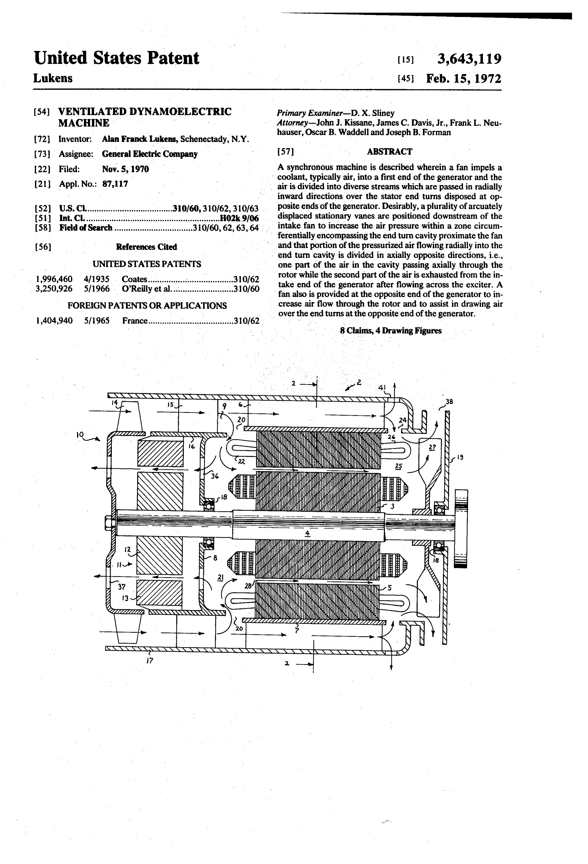
(73) Assignee: General Electric Company 57 ABSTRACT 22 Filed: Nov. 5, 1970 A synchronous machine is described wherein a fan impels a coolant, typically air, into a first end of the generator and the (21) Appl. No.: 87,117 air is divided into diverse streams which are passed in radially inward directions over the stator end turns disposed at op 52 U.S.C......................................310/60, 31062,310/63 displaced posite ends of the generator. Desirably, a plurality of arcuately (51 int.C. ..........................................................H02k9/06 stationary vanes are positioned downstream of the 58 Field of Search.................................. 31.0160, 62,63, 64. intake fan to increase the air pressure within a zone circum ferentially encompassing the end turn cavity proximate the fan 56 References Cited and that portion of the pressurized airflowing radially into the end turn cavity is divided in axially opposite directions, i.e.,
UNITED STATESPATENTs one part of the air in the cavity passing axially through the 1,996,460 4/1935 Coates............r.310162 rotor while the second part of the air is exhausted from the in take end of the generator after flowing across the exciter. A 3,250,926 5/1966 O'Reilly et al...........................310/60 fan also is provided at the opposite end of the generator to in FOREIGN PATENTS ORAPPLICATIONS crease air flow through the rotor and to assist in drawing air over the end turns at the opposite end of the generator.
1404,940 51965 France.....................................310/62 8 Claims, 4 Drawing Figures
\\ NNN N N S NNYSSNNNNV 38
KNS,
WYŽ l (s(NE)
ges
XYY
AAll-'t NN seN ...si.e.
N :::::::::::: w
2 Ns KHNKKHH-5
3 1 G IES) N \ | 2d p Zazza2222 NN
Page 2
Drawing sheet — no readable text.
Page 3
Drawing sheet — no readable text.
Page 4
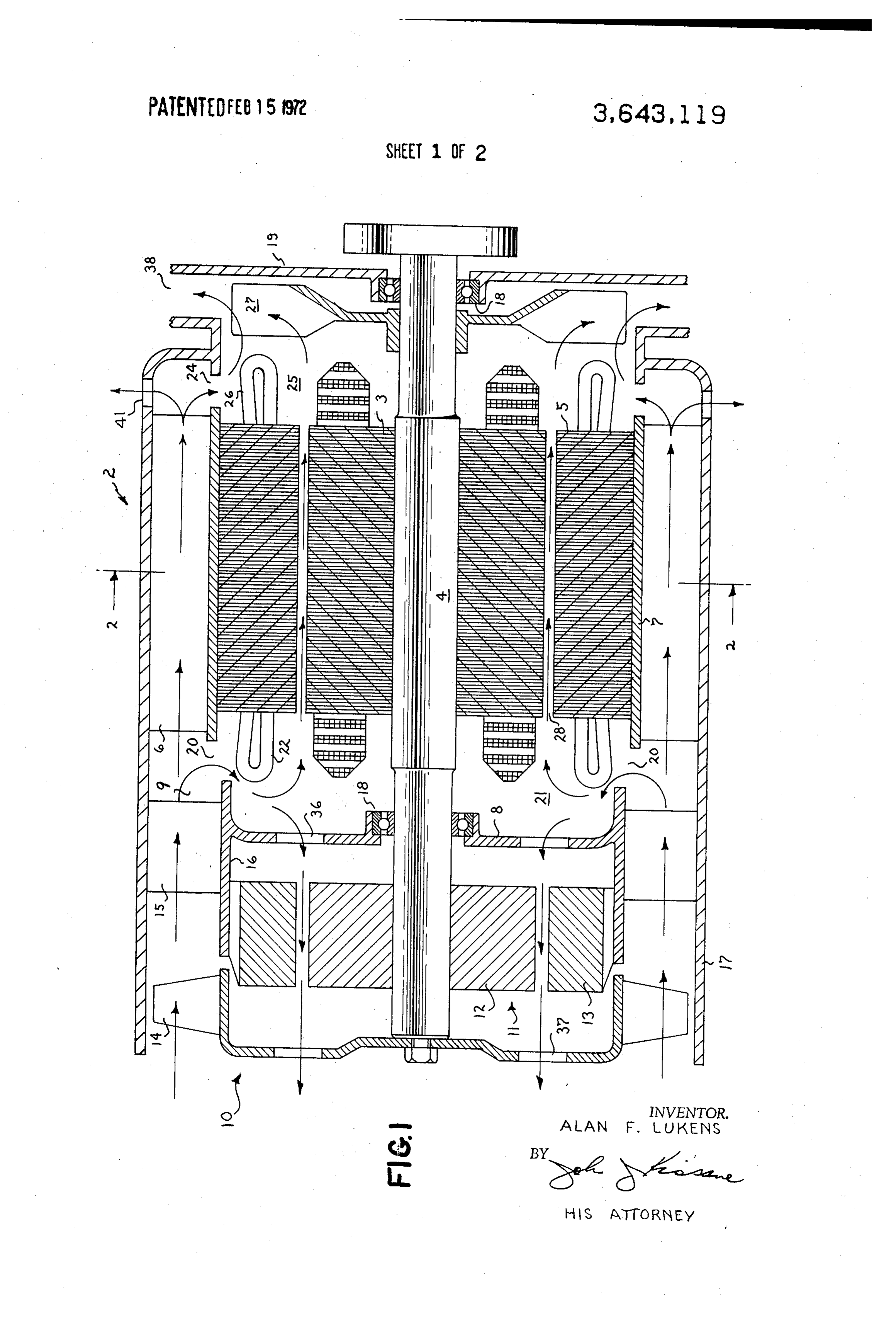
VENTELATED DYNAMOELECTRIC MACHINE BRIEF DESCRIPTION OF THE DRAwINGs BACKGROUND OF THE INVENTION A more complete understanding of this invention can be ob This invention relates to dynamoelectric machines and, tained from the following detailed description of a preferred more particularly, to dynamoelectric machines having im embodiment taken in connection with the accompanying proved means for circulating coolant therein. drawings in which:
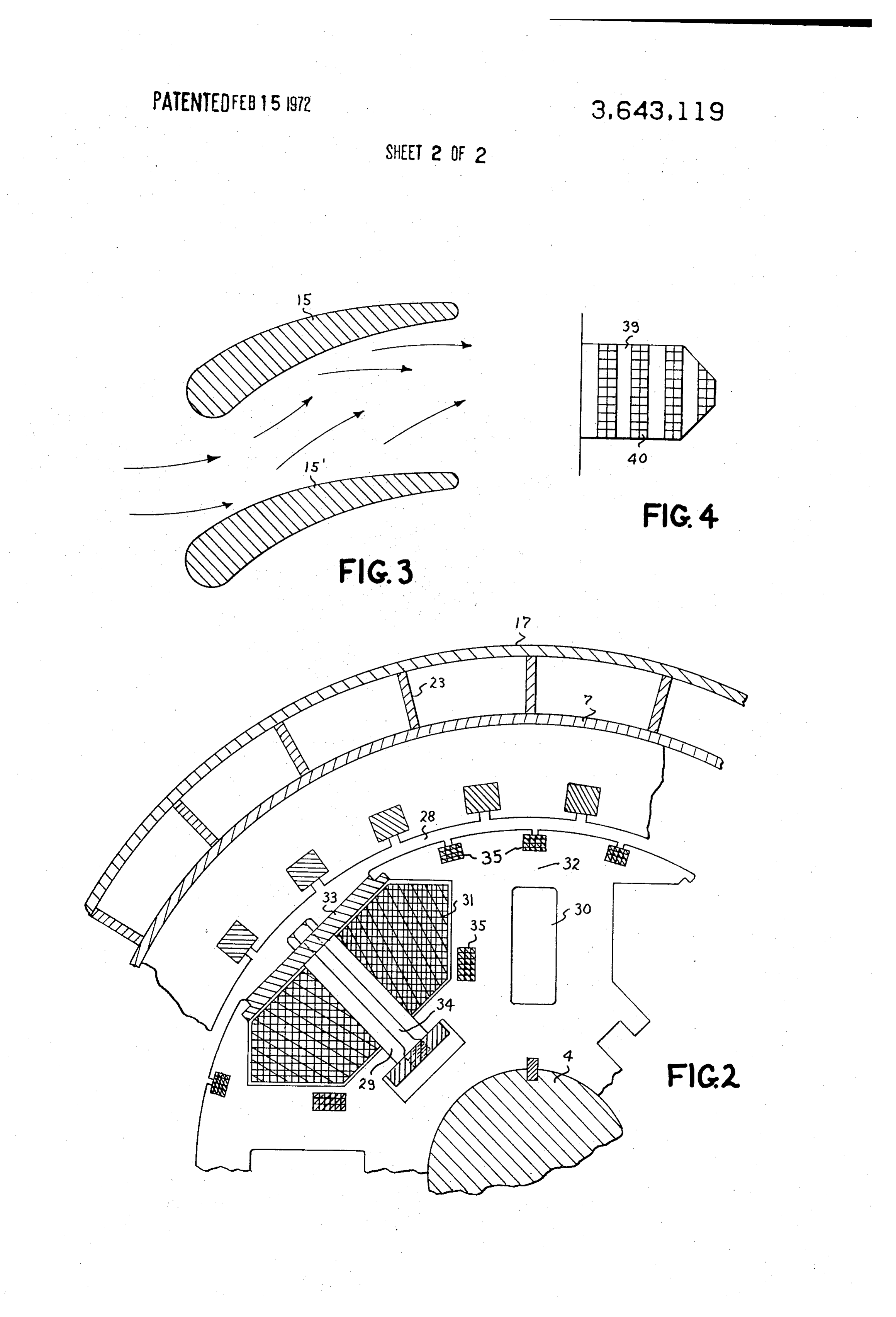
As dynamoelectric machines have become more efficient FIG. 1 is a longitudinal sectional view of a synchronous and more compact, the necessity for improved cooling means generator embodying the principles of the present invention, has become ever more pronounced. The smaller size of the FIG. 2 is a partially broken away view of a transverse sec machines and the increased electrical ratings thereof cause 10 tionFIG.
of the generator taken along line 2-2 of FIG. 1;
3 is an enlarged transverse section of a pair of adjacent the machines to run hotter, which in turn necessitates im vanes employed to increase the air pressure at the intake end proved insulation and more expensive materials and methods of the generator; and, of construction. In prior art machines, a coolant, e.g., air, typi FIG. 4 is an enlarged plan view illustrating a rotor end turn cally is pumped by means of a centrifugal fan into one end of configuration which functions as a radial fan to ventilate the the machine and various baffles or deflectors are employed to 15 inner direct the air to different areas within the machine. In most surface of the stator end turns. common ventilation systems, the air is blown directly into one DESCRIPTION OF THE PREFERREDEMBODIMENTS end turn cavity and passes over the radial inner surface of the end turns prior to being conveyed through various axial 20 Referring more particularly to FIG. 1, a synchronous passages within the machine for exhaust at the opposite end of generator 2 is illustrated which comprises a rotor 3 mounted the machine. Even with an elaborate system of baffles, it will on a shaft 4 for rotation within stator core 5. As will be recog be appreciated that the effectiveness of the air as a heat nized by those skilled in the art, rotor 3 and stator core 5 may transfer agent diminishes with span along the axial length of advantageously consist of a plurality of steel punchings assem the machine and those portions of the machine lying "- 25 bled together to form the respective laminated magnetizable downstream" of the source of cooling air are not cooled as ef structures. Stator core 5 is secured within a ribbed frame 6 ficiently as those parts of the machine first encountering the having a radially inner annular plate 7 contacting the entire newly admitted air. Moreover, pockets of stagnant air often outer periphery of the stator core to maximize heat transfer tend to be formed within the end turn cavities of conven from the stator core to the ribbed frame. Openings 20 are pro tionally cooled machines reducing heat transfer from the 30 vided at the input end of the frame to bleed air off from an an- is machines. nular high pressure zone 9 produced in part, by flow resistance . It is therefore an object of this invention to provide a thru ribbed frame 6. An exciter, generally identified by dynamoelectric machine having a more efficient cooling reference numeral 11 and comprising a rotor 12 mounted on system. shaft 4 in an axial disposition relative to stator 13, supplies It is a further object to provide a dynamoelectric machine 35 direct current energization for the windings of rotor 3 through wherein formation of stagnant air pockets within the end turn rectifiers (not shown) in conventional brushless excitation cavities is inhibited. fashion. A fan 10 also is fixedly secured to the forward end of It is a still further object to provide a dynamoelectric shaft 4, and is provided with a plurality of radially extending machine wherein temperature gradients along the axial length blades 14 which may advantageously have an airfoil cross sec
40 tion for impelling air into the machine in a generally axial . . .
SUMMARY OF THE INVENTION direction along annular zone 9 circumferentially disposed about exciter 11 (i.e., as indicated by arrows.designating the
In order to provide more efficient cooling of a dynamoelec airflow). Alternately, a radial fan having a suitable enclosure tric machine in accordance with this invention, a first fan is could be employed to produce the desired high volume axial provided at one end, designated the intake end, of the 45 flow of air within annular zone 9. Downstream from fan blades machine for impelling coolant along a circumferential zone 14 are a plurality of radially disposed stationary blades, or into the machine. The coolant will be described hereinafter as vanes, 15 rigidly mounted between inner housing 16 and outer being air although any suitable fluid coolant may be employed housing, or wrapper, 17 of the generator. These vanes without departing from the scope of this invention. The in generally are conventional in design and are employed as tur coming air then is dissected into two flow streams, one flow 50 bine blades to increase the air pressure within annular zone 9 stream passing axially within a ribbed frame contacting the downstream from the vanes. Because fan 10 desirably is stator while the remainder of the air is passed radially into the mounted at the extreme end of shaft 4, rotation of and support end turn cavity situated adjacent the intake end of the for the generator shaft is provided by bearings 18 situated machine to cool the radially outer surface of the end turns. within inner partition 8 and end plate 19 located at the ex The flow stream within the end turn cavity at the intake end of 55 haust end of the generator.
the machine is again divided with a portion passing through Adjacent a first end of stator core 5 proximate the vanes, the air gap and axial passages in the rotor, while the balance of openings 20 are disposed at arcuately spaced intervals the air flowing into the end turn cavity is directed in an axial between the edge of ribbed frame 6 and inner housing 16 to opposite direction to be exhausted from the intake end of the divert some of the airflow from annular zone 9 in a radially in machine. When that flow stream passing through the ribbed 60 ward direction into end turn cavity 21 to pass over the radially frame between the stator and machine housing arrives at the outer face of the stator end turns 22 situated therein. The rear end of the machine, a portion of the stream is directed remainder of the flowing air within annular zone.9 passes axi radially inward to impinge on the radially outer surface of the ally down the generator between ribs 23 extending upwardly end turns and the inwardly directed stream combines with the from annular plate 7 to maximize heat transfer from the stator air passed axially through the airgap and rotor to be exhausted 65 core to the air flowing within the ribbed frame. As will be from the rear end of the machine. Although the airflow recognized by those skilled in the art, ribs 23 may ad technique of this invention is particularly effective in associa vantageously be formed integrally with annular plate 7. At the tions with synchronous generators wherein the spacings opposite, or rear, end of the stator core 5, a second group of between the pole windings provide axial passageways for the arcuately displaced holes (identified by reference numeral 24) flowing air and the portion of air exhausted at the intake end 70 is situated for directing a portion of the air passed through the of the machine can be advantageously employed to cool the ribbed frame radially into end turn cavity 25 wherein the air exciter, it will be appreciated that the described air flow also flows over the radial exterior faces of end turns 26 while the can be employed in other machines, e.g., induction motors, majority of the air passed through the ribbed frame is ex without departing from the scope of this invention as defined hausted through apertures 41 within fan housing 17. The air in the claims. 75 within end turn cavity 25 then is exhausted radially from the
Page 5
generator by an auxiliary fan 27 mounted on shaft 4. As fan 27 machine to produce an axial cooling flow stream within a zone rotates, the fan provides suction drawing air from end turn situated radially outward of the end turns of said stator windings, means for dissecting said coolant flow stream into a cavity 21 through the axial passages extending through the generator. The suction produced by fan 27 also serves to draw. plurality of diverse flow channels, means for directing respec air at a high velocity through holes 24 to scrub the back of end 5. tive ones of said flow channels in a radially inward direction to turns 26. impinge individual flow streams upon the radially outer sur The primary axial passages through the synchronous faces of the stator end turns situated at opposite ends of said generator interior can be seen in FIG. 2 and generally com machine...and means for exhausting said coolant from said prise airgap 28 between the rotor and stator as well as axial machine. . : ...
ducts 29 and 30 formed between the pole windings 31 and O 2. A dynamoelectric machine according to claim 1, wherein within the pole arc portion 32 of the rotor, respectively. A said exhaust means are disposed at both ends of said machine. nonmagnetic keeper 33 fixedly secured in position by the including 3. A dynamoelectric machine according to claim 2 further overlying lips of the adjacent pole tips in association with stud means disposed at the coolant intake end of said machine 34 extending radially between the rotor and the center of the 15 stream. for increasing the pressure of said axial coolant flow
keeper serves to inhibit radial motion of the windings during 4. A dynamoelectric machine comprising a stator having motor operation. In conventional fashion, amortisseur windings inserted therein, a rotor mounted within said stator, windings 35 also are provided within the rotor. It will be ap first fan means for impelling coolant into a first end of said preciated that when other types of machines are employed, machine to form a pressurized zone circumferentially axial passages may be provided only through the rotor lamina disposed about an end turn cavity at the first end of said tions for facilitating the passage of air therethrough. machine, first distributing means for directing a first portion of FIG. 3 illustrates cross sections of a pair of the vanes 15, 15', which are located downstream from fan 10 in FIG. 1. said coolant axially along an annular zone disposed about the periphery of said stator, a cylindrical frame circumferentially
Each of the vanes has an airfoil cross section and is disposed at contacting the entire radially exterior surface of said stator, an angle to the inrushing airstream. As the incoming air flows over, the vanes, the aerodynamic configuration of the vanes 25 said lar frame having a plurality of ribs protruding into said annu zone, means for bleeding a portion of coolant radially in produces an annular zone of high-pressure cooling air directly ward from said pressurized zone to impinge upon the radially over end turn cavity 21 in accordance with well-known tur outer surface of stator winding end turns disposed at the first bine principles. end of said machine, means situated at the second end of said Some of the high pressure air in zone 9 then is directed 30 machine for directing a part of said first portion of coolant through openings 20 into end turn cavity 21 due to the pres radially inward to impinge. upon the radially outer surface of sure differential therebetween and the incoming air flows stator winding end turns disposed at the second end of said directly over the radially outer surface of end turns 22. A por machine and means for exhausting said coolant from the. tion of the air flowing over end turns 22 then proceeds second end of said machine.
backwardly within the generator through openings 36 in parti 35 5. A dynamoelectric machine according to claim 4 further tion 8 to cool exciter 11 prior to being discharged from including means for further directing part of said portion of openings.37 in the hub of fan 10. A second portion of the air coolant bled into the end turn cavity at the first end of said passing across end turns 22 flows through airgap 28 and axial machine axially through said rotor and means for directing a ducts 29 and 30 within rotor. 3 (due to pressure in cavity 21 second part of said bled portion of coolant in an axially op and suction produced by fan 27) before being exhausted radi 40 posite direction.
ally through openings 38. That portion of the air from high 6. A dynamoelectric machine according to claim 5 further pressure annular zone 9 not directed into end turn cavity 21 including exciter means disposed on a common shaft with said flows back through ribbed frame 6 absorbing heat generated rotor, means for passing said second part of said bled portion in the stator core, and a majority of the air flowing in the of coolant across said exciter means and means disposed at ribbed frame is exhausted through apertures 41. A portion of 45 said first end of said machine for exhausting said second part the air, however, passes radially inward over end turns 26 to of said second portion of coolant.
cool the radial outer surface of the end turns whereupon air 7. A dynamoelectric machine according to claim 6, wherein combines with air drawn through the interior of the generator said first fan means is an axial fan situated radially outward of to be exhausted through openings 38. said exciter means, said means for passing coolant across the Additional circulation of air within the end turn cavities also 50 exciter includes an apertured partition situated between said is achieved by shaping the end turns of pole windings 31 in a rotor and said exciter and said means for exhausting coolant manner producing a plurality of axially separated turns having . from said second end of said machine includes a radial fan air gaps 39 between the separate groups of turns 40 as shown coaxially mounted with said rotor.
in FIG. 4. The air gaps between the groups of turns not only 8. A dynamoelectric machine comprising a stator having assists in cooling the rotor end turns but the elongated exten 55 windings disposed therein, a rotor mounted within said stator, sion of the end turns into the end turn cavity increases circular first fan means coupled to said rotor for impelling coolant into tion of the air within the cavity to scrub the underside of the a first end of said machine, a plurality of vanes disposed within stator by acting as a radial fan. In general, at least three, and the flow path of said first fan means for increasing the pressure approximately six, axially separated groups of turns are of coolant passing between the vanes to develop a zone of preferred at the rotor winding end turns to maximize cooling 60 pressurized coolant downstream of said vanes, means for dis of the field winding although a lesser number of separated tributing a first portion of said pressurized coolant in a radially turns could be employed if desired. inward direction into the end turn cavity situated at said first As can be appreciated from the foregoing description, the end of said machine to pass said first portion of coolant over present invention provides improved cooling of dynamoelec the radially outer surface of the end turns situated therein, tric machines with structurally simple ventilating passages. 65 means for distributing the remainder of said pressurized coo Complex ductwork and baffles are rendered unnecessary and lant along an annular Zone encompassing said stator, a portion increased cooling of the entire machine is effected. of said remainder passing in a radially inward direction into . What is claimed as new and desired to be secured by Letters to passthe end turn cavity situated at the second end of said machine Patent of the United States is: . . . . . over the radially outer surface of the end turns situated 1. A dynamoelectric machine comprising a stator having 70 therein and means for exhausting said coolant from both ends windings inserted therein, a rotor axially mounted within said of said machine. * stator, means for impelling coolant into one end of said
Provenance
- Collection
- Cited prior art
- Original PDF
- patentimages.storage.googleapis.com →
- Filed
- 1970-11-05
- Pages
- 5
- Method
- pdftotext (the PDF's own text layer) + pdftoppm 300dpi page scans
- Source
- Google Patents bibliographic record
- Granted
- 1972-02-15
- Inventors
- Alan Franck Lukens; General Electric Co
- Transcribed from
- patentimages.storage.googleapis.com →