patent · US6172429
Hybrid energy recovery system
9 January 2001
Page 1 — bibliographic record
(12) United States Patent (10) Patent No.: US 6,172,429 B1 Russell (45) Date of Patent: Jan. 9, 2001
(54) HYBRID ENERGY RECOVERY SYSTEM L. Kamm, Understanding Electro-Mechanical Engineering, The institute of Electrical and Electronics Engineers, Inc.
(76) Inventor: Thomas H. Russell, 14 Sulgrave Rd., (1996) pp. 67–81.
West Hartford, CT (US) 06107
T. Russell, Direct Gain Industrial Building Without Redun (*) Notice: Under 35 U.S.C. 154(b), the term of this dancy Has Quick Pay Back, International Solar Energy patent shall be extended for 0 days. Society, Inc.
(21) Appl. No.: 09/545,294 L. Valigra, Carbon-Fiber Material May Open The Door To Smart Structures, Christian Science Monitor (Mar. 26, (22) Filed: Apr. 7, 2000 1998).
Related U.S. Application Data Dye, Advanced Chip Revs Up Electric Car Technology, Los Angeles Times Syndicate (Oct. 12, 1998).
(62) Division of application No. 09/232,986, filed on Jan. 19,
(60) Provisional application No. 60/072,741, filed on Jan. 27, * cited by examiner
(51) Int. Cl." .................................................... F03D 9/00 Primary Examiner Nicholas Ponomarenko (52) U.S. Cl. ................................ 290/54; 290/55; 290/4 R (74) Attorney, Agent, or Firm McCormick, Paulding & (58) Field of Search .................................. 290/43, 44, 54, Huber LLP
A System for recovering energy from the natural and man
made Sources of wind, water and Sunshine provides within 906,754 12/1908 Tschirgi. a given local area wind, water and Solar apparatuses for 3,956,902 5/1976 Fields, Jr. ................................... 62/3 converting all three wind, water and Solar energies to 4,039,849 * 8/1977 Mater et al. ... 290/55 electrical power to provide a reasonably Steady Supply of 4,061,926 12/1977 Peed ......................................, 290/55 electrical power at all times. The wind and water apparatuses 4,200.783 4/1980 Ehret .......... ... 219/365 may be double Speed Savonius rotor electrical generating 4,319,141 3/1982 Schmugge .............................. 290/52 4,379,972 4/1983 Sosa et al. ............................. 290/44 apparatuses each of which includes two Savonius type rotors 4,398,096 8/1983 Faurholtz ............................... 290/55 mounted adjacent to one another for rotation about a com 5,262,693 * 11/1993 Holka ... ... 310/121 mon axis with the blades of the rotor units being arranged So 5,332,354 7/1994 Lamont ................................. 415/42 that the rotor units rotate in opposite directions relative to 5,394,016 2/1995 Hickey ................................... 290/55 one another under the influence of a given wind or flow of 5,808,369 9/1998 Whelan .................................. 290/55 water. The electrical generator of each apparatus includes a 6,097,104 9/2000 Russell ................................... 290/54 field means attached to one of the two rotors and an armature 6,100,600 8/2000 Pflanz ..................................... 290/54 attached to the other of the two rotors so that the field means
OTHER PUBLICATIONS and armature rotate relative to one another at a speed P. Gipe, Wind Power for Home and Business, Chelsea Green approximately double the Speed of rotation of each of the Publishing Company (1993) pp.101-169. rotor units about the common rotational axis. J. Park, The Wind Power Book, Cheshire Books (1981) pp.
71-76 and 91-98. 6 Claims, 5 Drawing Sheets
Page 2
Drawing sheet — no readable text.
Page 3
Drawing sheet — no readable text.
Page 4
Drawing sheet — no readable text.
Page 5
Drawing sheet — no readable text.
Page 6
Drawing sheet — no readable text.
Page 7
HYBRD ENERGY RECOVERY SYSTEM Natural energy assets Such as Sun, wind, and flowing water can be considered as being of two types: (a) inherently
CROSS REFERENCE TO RELATED natural, and (b) by-products of human activities. For APPLICATION instance, we brightly light buildings to attract attention, parking lots to be safe, Signs to be seen. This light is a
This application relates to Provisional U.S. patent appli by-product of human activity and it is possible to recapture cation Ser. No. 60/072,741 filed on Jan. 27, 1998, the filing Some of it with photovoltaic devices without interfering with date of which is claimed here and it is a divisional applica the purpose for which the light was initially intended. AS tion divided from prior application Ser. No. 09/232,986 filed another example, it is possible for photovoltaic material to on Jan. 19, 1999 now U.S. Pat. No. 6,097,104. be carried on South facing highway noise barriers to pick up enough light from the headlights of passing trucks, buses
FIELD OF THE INVENTION and cars to Supplement natural Sunlight picked up by the photovoltaics
This invention concerns a hybrid System for recovering thousands of trucks, during daytime. In the case of wind energy, energy from naturally occurring energy Sources Such as the at high Speed cause buses, and cars driving down highways Sun, the wind and flowing water, and from presently wasted enhanced and channeled bygusts 15 major of wind which are often manmade Sources of light, wind and flowing water, by barriers. A Series of properly designedformations land wind and noise powered elec converting the energy contained in these Sources into elec trical generators can generate electricity from these gusts. In trical and mechanical energy to be used either locally close the case of flowing water power, large amounts of water run to the places of recovery or to be included into a far-reaching from hills or buildings when it rains, and this flowing water electrical power transmission network, and it also deals can be channeled and directed to Small water wheel electri more Specifically with the construction of apparatuses and cal generators at lower levels or into ponds that hold the combinations of apparatuses used in the making up of Such water and release it when Supplemental electrical power is hybrid energy recovery System. needed.
BACKGROUND OF THE INVENTION 25 High buildings in heavily built up areas can be cost free mounts for South facing photovoltaics to capture Solar
A hybrid energy recovery System is one wherein energy is energy from the Sun or can be used to channel wind or rain recovered from a number of different energy Sources located water to Small wind powered or water powered electrical within a relatively Small area Such as, for example, the area generators, and Smaller flows of water can be combined and Surrounding and including the Space occupied by a given directed into larger flows to power turbines driving more architecture Such as a house, apartment, factory, office powerful electrical generators.
building or a set of Such buildings. Such a hybrid energy From what has been said above, one can visualize a recovery System is known, for example, from: Russell Direct number of high buildings connected by glass enclosed Gain Industrial Building Without Redundancy Has Quick walkways acroSS Streets, possibly at Several levels. Some Pay Back, proceedings of the Fifth National Passive Solar 35 walls that face roughly South may have photovoltaic gener Conference, University of Delaware. ating devices mounted on them. When wind is deflected There is increasing agreement around the World that from buildings causing areas of high wind Velocity, this high people would benefit from a change from nuclear fuels, coal, wind Velocity can be used by putting a Series of Small rotor oil and gas as energy Sources to clean indefinitely renewable type wind electrical generators between the two walkways and locally available natural energy Sources Such as 40 which will deflect and increase the wind Speed and electrical Sunshine, wind, and flowing water to generate useful elec generation. Service could be made easy by access to the trical power. The use of each one of Sunshine, wind and rotors through the ceiling of the lower walkway or the floor flowing water as an energy Source by itself has its Strengths of the upper walkway.
and weaknesses, Such as time of day or night, Season, In considering a System for combining the recovery of weather conditions, location of generators near to points of 45 Solar, wind, and water energy, it will be noted that Solar use, Special land and directional and topographic energy recovery devices are leading the way with rapid requirements, the amount and cost of required real estate, technological breakthroughs. The efficiency of the devices aesthetic considerations, Safety considerations, noise are increasing and the prices of them are falling. Reasonably considerations, etc. However, when these natural and man efficient and reasonably inexpensive water-powered genera made Sources of energy are used in combination to generate 50 tors are also available. The conversion of wind power into electrical power, they can go a long way in Solving another electrical energy is, however, the crucial element in a natural major and heretofore expensive problem, namely that of energy recovery System.
providing a reasonably Steady and continuous Source of Wind energy has the potential to be the major energy electricity for Storage in batteries and other energy Storage provider of a recovery System, but Suffers from clinging to devices and/or for use in powering lamps, motors and other 55 natural wind resources only. The emphasis has been on devices. natural wind and the few and costly sites that naturally have It is also important to local communities that the equip the necessary wind Speeds. New developments have focused ment required to convert natural energy Sources to electricity on complicated windmills of the propeller and DarrieuS rotor be easy to manufacture and assemble, be easy to install, and technologies that Supply high efficiency, but also have high be easy to Service and replace when necessary by fully 60 initial expense, require high towers in most locations, are qualified local labor. This keeps the money to be spent in the Subject to expensive and dangerous Servicing atop high community, and helps Solve a current major worldwide towers, require a lot of Space, cannot effectively utilize problem occurring in many communities and nations of intermittent gusts (which is very wasteful), and can be having to spend vast amounts of monies out of town or out destroyed by wind shears. These complicated windmills also of the nation to pay increasing prices for increasingly Scarce 65 require time to Swing to face the quick changes in wind and unhealthy non-renewable energy material Such as direction in the case of propeller-type units, and have nuclear fuel, oil, gas and coal. uncertain Stalling and Starting problems in the case of
Page 8
Darrieus designs. Both propeller devices and DarrieuS the two rotor units respectively carrying or being otherwise devices have niche applications where they do well, but connected to field and armature parts of an electrical gen these are limited. erating device, which field and armature parts cooperate Transporting electricity long distances is increasingly during rotation of the rotor units to generate electrical power, expensive and dangerous, and the Source of most Service the Speed of rotation of Said field and armature parts relative interruptions and accidents. The new rules Separating dis to one another being effectively double the speed of rotation tribution from generation further camouflages costs that are of each one of the rotor units relative to the common axis, already misleading because emergency costs often are paid So that the electrical power is generated at a high Speed or by local police, fire departments, disaster organizations, and frequency more Suited to the efficient generation of electrical the Federal government. With remaining large monopolies, power than is the lower Speed of either rotor unit taken by utility control boards are less effective, and individuals have itself.
little influence short of forming cooperative or generating The invention also resides in the energy recovery System their own power on Site. Even Small wind generating and of the invention including both a double speed Savonius photovoltaics can operate thermoStats, pumps, and blowers rotor apparatus for generating electrical power from wind to maintain critical heat and communications during pro 15 and another double Speed Savonius apparatus for generating tracted outages. electrical power from flowing water. The Savonius rotor as a wind energy recovery device has The invention further resides in making the rotor of the long been used for Such high torque applications as pumping wind driven electric power generator of materials, Such as water and grinding grain. It is a simple device which can, if ones including carbon fibers, whereby the material of the well designed, use rotor units formed in one piece to very rotors themselves can be used as electrical conductors, as accurate Standards and using new materials, with possibly electrical energy Storage means, and/or as photovoltaic Self-lubricating properties that are recyclable and inexpen devices for converting Solar energy to electrical energy; Sive. The rotor unit is then mounted on a vertical pipe or and/or in providing Separate photovoltaic elements on Sur other Support passing vertically through the center of the faces of the rotors so that the rotors not only contribute to the unit so that the unit revolves around the pipe when the wind 25 recovery of energy from the wind or flowing water but also blows onto the unit from any direction with Sufficient contribute to the recovery of energy from the Sun. In the case Velocity. That is, the Savonius rotor can use wind from any where the carbon fibers are used for conducting electricity, and all directions at all times. This simple two-bladed they can be used as conductors for conducting the electricity Savonius rotor, or similar rotors with three or more blades, produced by the photovoltaic devices associated with the operates at relatively low speeds in comparison to Some rotors, as conductors for conducting electricity to or from other types of wind-powered rotors and has usually been parts of the electrical generator associated with the rotors, or considered to be inefficient for electric generating purposes, as conductors for conducting electricity in a control circuit with efficient generation of electricity usually being consid associated with the electrical generator. ered to require higher rotor Speeds than generally available 35 The invention also resides in a double speed Savonius from Savonius rotors. rotor apparatus of the above-mentioned kind wherein the The object of the present invention is, therefore, to apparatus includes a means for Sensing the Speed of each of provide a hybrid energy recovery System for recovering the two rotors and an associated control System for control energy in electrical and/or mechanical form from a combi ling the generator portion of the apparatus to control the nation of Solar, wind, and flowing water energy Sources, both 40 Speeds of the rotors through the use of a regenerative or naturally occurring and man made. dynamic braking effect applied to the rotors by the generator, A further more detailed object of the invention is to as for example, to keep the rotors from reaching possibly provide a Savonius-type rotor apparatus which can be used Self-destructive speeds or from rotating at undesirable low for generating electrical power from wind power and which Speeds with the power absorbed by the generator in braking generates efficiently at higher speeds of electrical power 45 the Speeds of the rotors being recovered as additional useful production than do conventional Savonius rotors, with Such electrical power.
higher Speeds of electrical power production being obtained The invention also resides in a construction of the double without gears or other mechanical Speed-increasing devices. Speed Savonius rotor apparatus particularly well adapted for Another object of the invention is to provide a Savonius use with flowing water or in other situations where the type rotor apparatus of the above-mentioned kind which can 50 apparatus is used in wet or damp environments. also be used in the energy recovery System of the invention The Wind Book by Jack Park published in 1981 by to recover electrical energy from the energy of flowing Cheshire Books in Palo Alto, Calif. has a photograph on water, and which can also be used for recovery of Solar page 75 of a three-tiered Savonius S rotor designed to energy,the Savonius rotor having a relatively large Surface generate electricity. In the background are transmission lines area in comparison to propellers and many other types of 55 and towerS Suggesting this was a Serious effort to develop wind driven devices and, therefore, being well Suited to wind electric generation by utilities. Traditional Savonius S additionally Serve as a Solar energy recovery device. rotors worked very differently from the wind electric Savonius rotors in this patent application. The S rotorS and
SUMMARY OF THE INVENTION the vertical shift tower rotated together all in one direction The invention resides in a System for producing electrical 60 and the bottom end of the shaft turned the water pump in the energy from combined energy Sources of Sunshine, wind, well or other devices.
and flowing water. More specifically, the invention resides in Park says in his write-up “A rotor that slows air down on Such a System wherein at least the apparatus for producing one side while Speeding it up on the other, as does the S electrical power from wind is an apparatus made up of two rotor, is Subject to the magnus effect: lift is produced that Savonius rotor units, with the two rotor units being mounted 65 causes the machine to move in a direction perpendicular to end to end for rotation about a common central axis in the wind. Spin on a baseball causes it to curve because of the opposite directions of rotation and with the adjacent ends of magnus effect. An S rotor can easily experience lift forces
Page 9
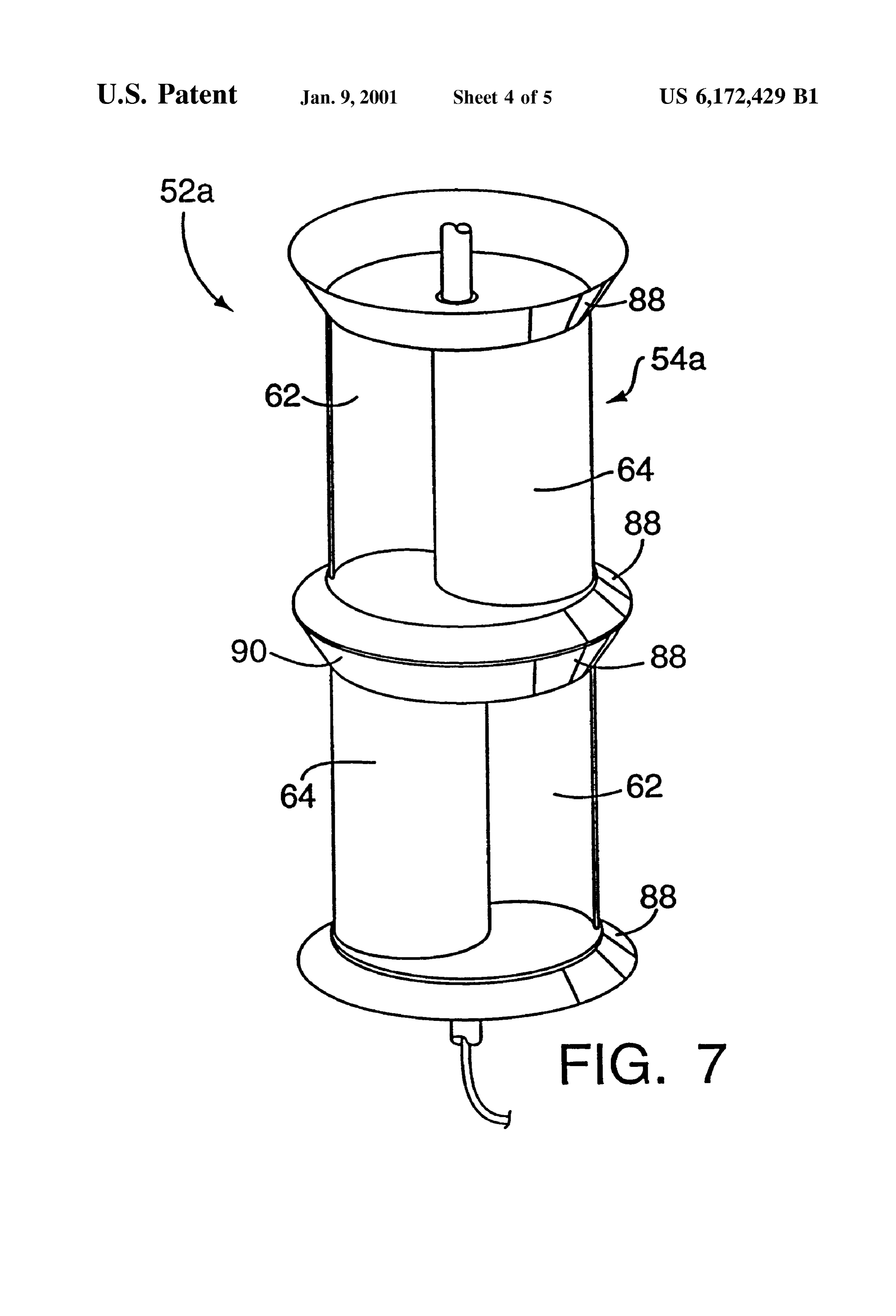
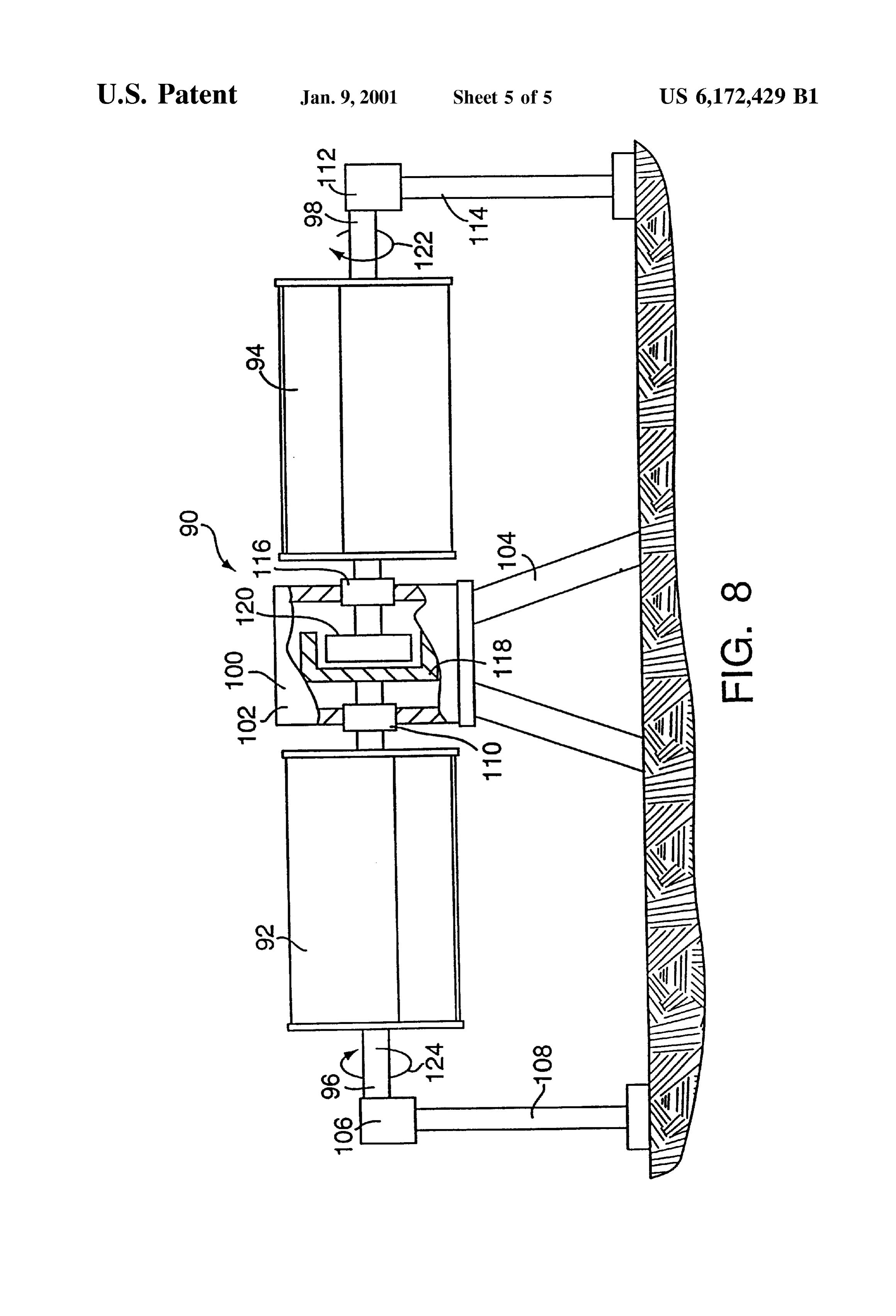
S 6 equal to three times the drag load placed on the Supporting FIG. 5 is a transverse sectional view taken on the line tower. Many owner-built S rotors have toppled to the ground V-V of FIG. 3.
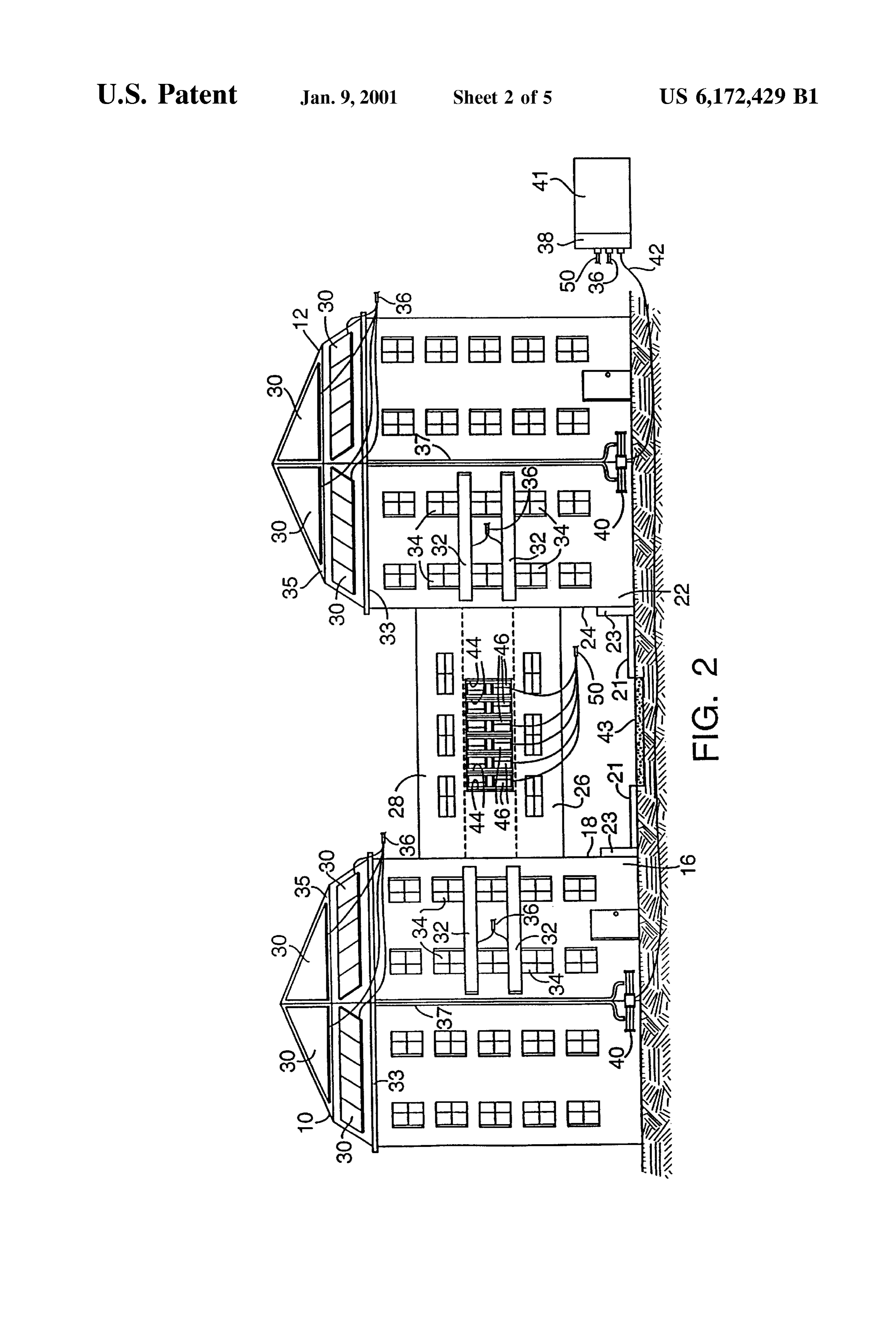
because their designers overlooked this phenomenon.” FIG. 6 is a complete perspective view of the double speed In addition to the vertical central shaft the picture shows Savonius energy recovery apparatus of FIG. 3. a large heavy iron external frame with a very large footprint FIG. 7 is an elevational view of a modification of the plus 4 guy wires and a large concrete base. Also, the rotors double speed Savonius energy recovery device of FIG. 3. appear not to overlap the vertical shaft to deflect wind to the FIG. 8 is an elevational view of another modification of back Side of the drag blade which increases performance the double speed Savonius energy recovery device of FIG. substantially, according to Paul Gipe, author of Wind Power, 3, with parts of the generator housing being broken away to for Home and Business published by Chelsea Green reveal the enclosed field and armature of the generator. Publishing, White River Junction, Vt. in 1993. Gipe says on page 105 that 33% is the theoretical amount of energy DETAILED DESCRIPTION OF THE Savonius S rotors can extract from the wind. While on page PREFERRED EMBODIMENT 105, he states the betz limit for lift devices is 59.3% but The energy recovery System of this invention may be optimally designed rotors reach levels slightly above 40%. 15 asSociated with many different geophysical and architectural Usable energy is even leSS because energy is lost in Situations where transmissions, generators, and power conditioning (the energies are all Sources of Solar, wind, and flowing water available, although in differing degrees equipment necessary to convert the energy into a form we depending on time of day, weather conditions, and other can use). There are also loses due to rapid changes in wind factors, within a Small area, to provide a reasonably con Speed and direction that are not accounted for in our simple tinuous and useful amount of electrical power to be used by formulas. On page 62, he sums this up and comes up with lamps, motors, and other electrical appliances, with or an overall efficiency of 29%. So there are hard numbers to without accompanying Storage batteries, in the local area or back the case for new State-of-the-art Savonius counter rotating wind electric generators on Site which can Supple to be Supplied to a more far-reaching electric power trans mission network, with the System also possibly providing ment natural wind with man-made architectural contribu 25 mechanical power for directly mechanically powering tions to wind Speed as well as man-made winds otherwise mechanical devices Such as pumpS and grinders. wasted.
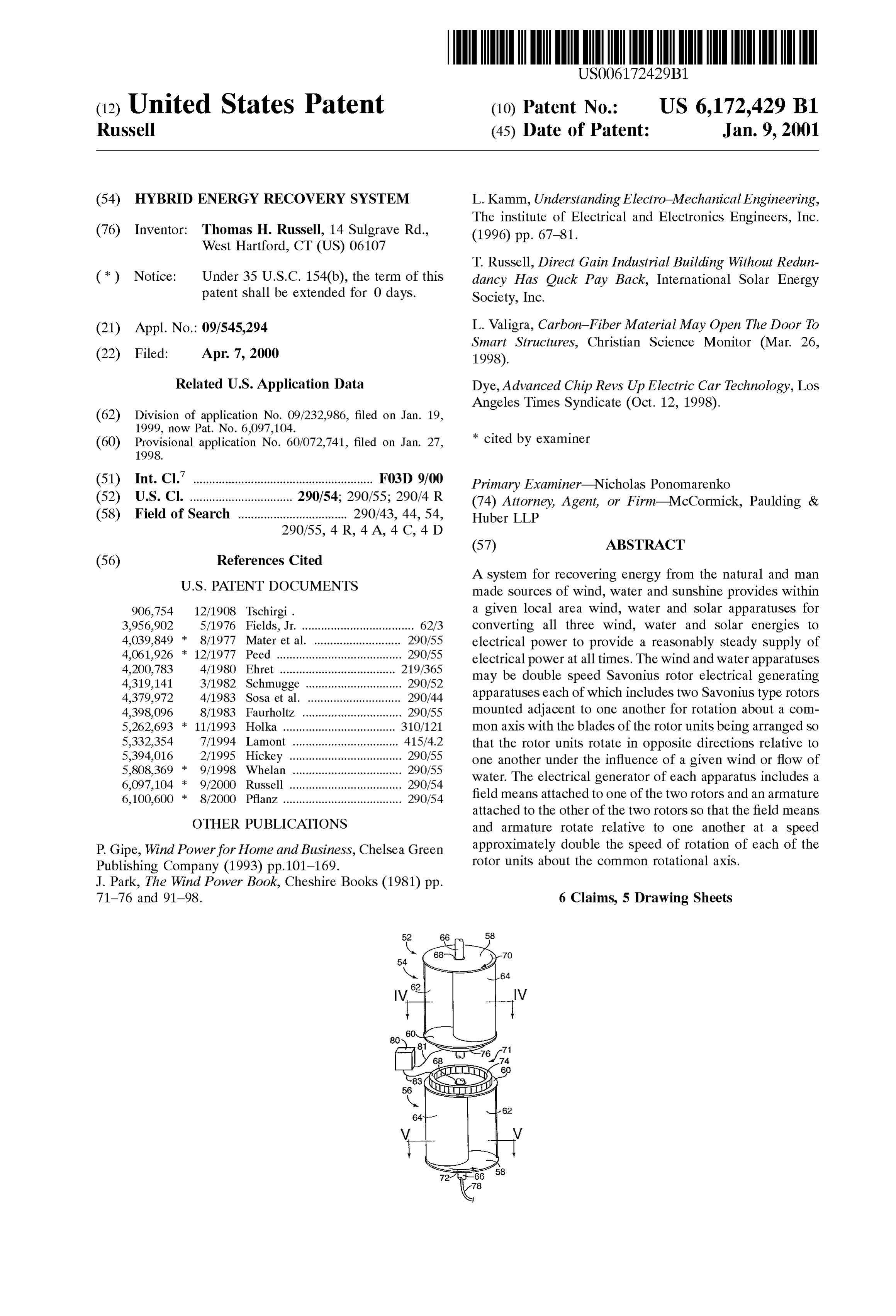
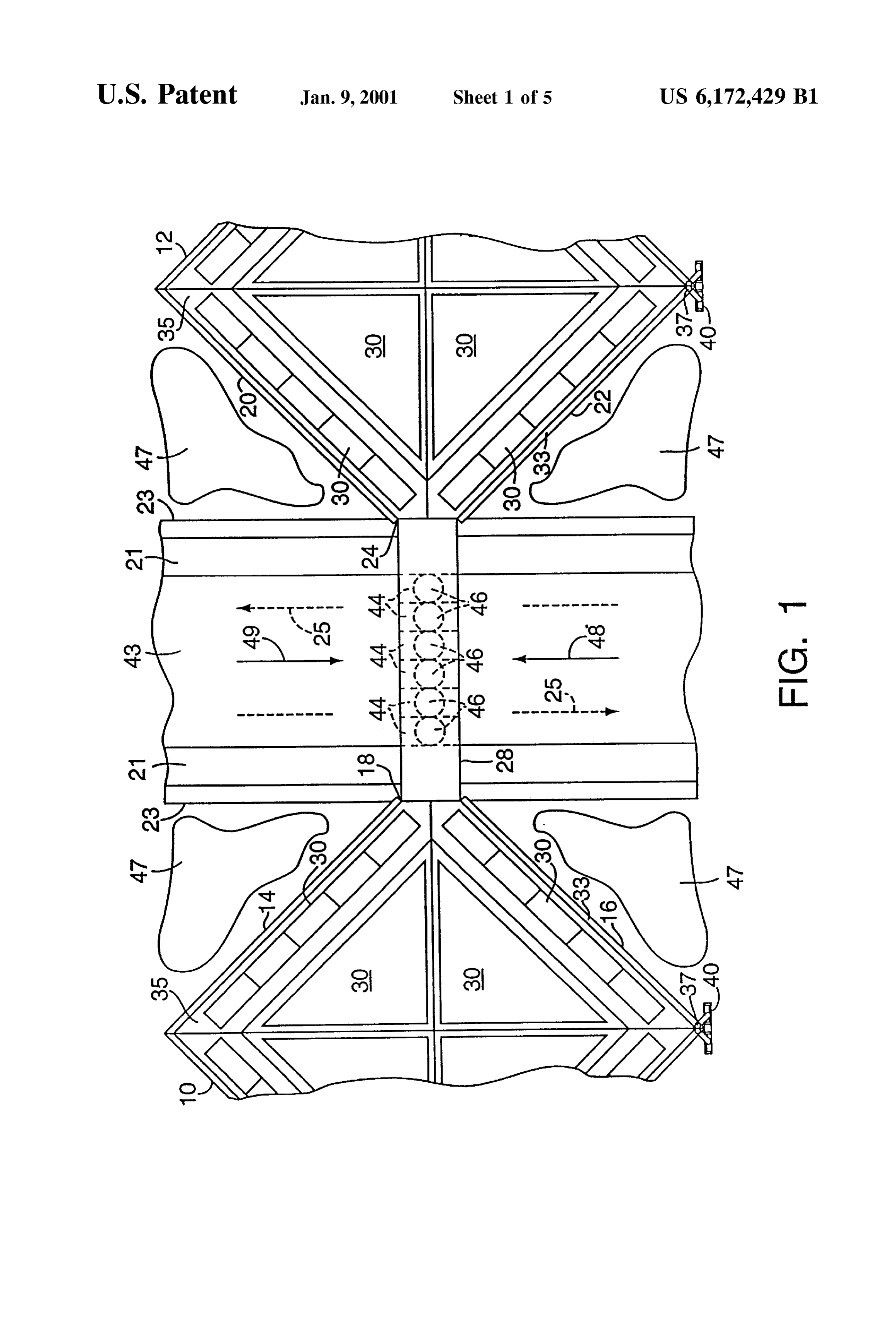
Referring to FIGS. 1 and 2, the system of the invention is
Moving water can be a particularly valuable contributor to shown applied to an exemplary architecture. The illustrated hybrid energy Systems because (1) it can be stored high up architecture consists of two multi-storied buildings 10 and where it is collected and held as potential energy to be 12. As seen in FIG. 1, the two buildings 10 and 12 are of released as needed, and (2) it can generate 24 hours a day generally Square or rectangular footprints with the building regardless of weather and is usually most available in winter 10 having two vertical sidewalls 14 and 16 converging to a when photovoltaics are least productive and when energy corner area 18 and with the building 12 having two vertical demand is highest. Once installed Small and micro turbines 35 Sidewalls 20 and 22 converging to a corner area 24. Between can generate at up to ten times lower cost than photovoltaics. the two buildings are two elevated walkways 26 and 28 Moving water rotors work best when they rotate at connecting the two buildings 10 and 12, with the illustrated roughly the same Speed as the Speed of the water that is their walkway 26 being located at the second floor level of the primary Source. Low head moving water rotors turn slowly two buildings and with the illustrated walkway 28 being at Speeds roughly similar to wind Speeds. So basically the 40 located at the fourth floor level of the two buildings. Same counter rotors that generate electricity by double For recovery of Solar energy, both of the buildings carry generating Speed should work well for low head water. one or more arrays 30 of photovoltaic cells or elements of High head water moving fast but with smaller volume known construction. AS illustrated, Some of these photovol neet micro pelton type rotors which turn So fast they need taic arrays can be arrays 30 located on the roofs 35 of the two fans to cool them and even SO equipped wear out their rotors 45 buildings, and other arrays can be arrayS 32 located at quickly. Here again counter rotating rotorS have the capacity available places on one or more of the vertical walls of the to generate at the required High Speed with each counter building, as for example between horizontal rows of win rotating rotor that the water hits having to rotate at only dows 34 as shown in FIG. 2. The electrical power generated about half the Speed of the generator. by the individual arrays are conducted by Suitable conduc Still other features of the invention will be apparent from 50 tors to a transmission cable 36 for transmission to the inlet the claims and from the following description and accom 38 of a local electrical energy receiving and utilizing means panying drawings describing preferred embodiments of the 41, the means 41, as mentioned, possibly including various invention. lamps and motors used locally in or immediately outside of the buildings 10 and 12. The means 41 may also include
BRIEF DESCRIPTION OF THE DRAWINGS 55 Storage batteries for Storing exceSS amounts of electrical
FIG. 1 is a plan view of an energy recovery System energy and for during periods of peak electrical energy production
Supplying amounts of make-up electrical power embodying this invention in association with an exemplary during periods of low electrical power production. Further, architecture.
the means 41 may also include or be a connection to a
FIG. 2 is a front elevational view of the system and 60 far-ranging electrical transmission network for Supplying architecture of FIG. 1. exceSS amounts of produced electrical power to the network. FIG. 3 is a fragmentary perspective, exploded view of a For recovery of energy from water, the system of FIGS. double-speed Savonius wind or water driven electrical 1 and 2 includes an arrangement of gutters and drains for power generating energy recovery apparatus used in the collecting rainwater striking the buildings 10 and 12 and for system of FIG. 1. 65 channeling the collected water to one or more water-driven FIG. 4 is a transverse sectional view taken on the line electrical generating units. The arrangement of gutters and IV-IV of drains and the number and construction of the water driven
Page 10
generators used in a particular application may vary widely. known Savonius design, with each rotor unit including two By way of example, in FIGS. 1 and 2 for each of the circular end plates 58 and 60 and two blades 62 and 64. Each buildings 10 and 12 the gutters include gutters 33 for blade 62 and 64 is of semi-cylindrical shape, and if wanted, collecting rainwater flowing from the roof 35, and the drains the two blades of each rotor can be made by Starting with a include a drain 37 for conducting water from the gutters 33 cylindrical tubular body and cutting the body along two lines to a water-powered electrical generator 40. The power extending parallel to the axis of the body and located in a generated by each generator 40 is conducted by a transmis common plane passing through the axis of the body. The sion line 42 to the electrical power inlet 38 of the utilizing arrangement of the two blades of each rotor relative to one means 41. another is preferably such as shown in FIGS. 4 and 5, but AS to the recovery of energy from wind, in the architec other arrangements of the blades relative to one another, and ture of FIGS. 1 and 2 between the two walkways 26 and 28, even three or more blades, may be used in each rotor without as Seen in FIG. 2, are a number of through-going passage departing from the invention.
ways 44, each of which passageways contains a wind-driven The two rotor units 54 and 56 are supported on a fixed electrical generating unit 46. pipe or shaft 66 for rotation relative to the shaft about the It will, therefore, be understood from FIG. 1 that when a 15 shaft's longitudinal axis, as by Suitable bearingS 68 located wind is blowing generally in the direction of the arrow 48, at each end of each rotor unit.
the two walls 16 and 22 of the two buildings 10 and 12 Although the two rotor units 54 and 56 are of identical channel the wind toward the passageways 44 and thereby construction, an important aspect of the invention is that Significantly increase the Speed of the wind at the place they are mounted on the Supporting pipe 66 So as to rotate where the wind encounters the generating units 46. in opposite directions about the pipe 66 when encountered Likewise, when the wind is blowing generally in the direc by a wind traveling in any given direction. In particular, to tion of the arrow 49, the two walls 14 and 20 of the two obtain this difference in rotational direction, the two rotor buildings 10 and 12 channel the wind to the passageways 44 units 54 and 56 are mounted on the pipe 66 so that their two and likewise increase the Speed of the wind as it encounters similar end plates 60,60 are located adjacent to one another the generating units 46. The power generated by each of the 25 as shown in FIG. 3. As a result of this, the blades 62 and 64 units 46 is transmitted to a transmission cable 50 which of the rotor unit 54 face in directions opposite to the conducts the power to the inlet 38 of the power-receiving corresponding blades 62 and 64 of the rotor unit 56, as seen means 41. in FIGS. 4 and 5. Accordingly, when encountered by a wind It should be noted from FIGS. 1 and 2 that having the of any direction, the upper rotor unit 54 of FIG. 3 will rotate walkways 26 and 28 spaced vertically from one another by in the direction of the arrow 70 and the lower unit 56 will the equivalent of the height of one floor of each building rotate in the opposite direction of the arrow 72. allows for Such a design that the wind-powered generators AS mentioned, Savonius rotors are known to operate at can be made accessible for maintenance and/or replacement relatively low rotational Speeds which are considered not from either the roof of the passageway 26 or the floor of the 35 Suited to efficient electrical power generation. In the present passageway 28. invention, however, the fact that the two rotors 54 and 56 Preferably, and as best seen in FIG. 1, the passageways 26 rotate in opposite directions is taken advantage of to provide and 28 are located above a street 43, bordered by sidewalks for the generation of electrical power at double the Speed or 21 and walls 23, passing between the two buildings 10 and frequency Such power would be generated by using only a 12, the Street being a two-way Street as indicated by the 40 Single rotor unit. This is done by providing an electrical broken arrows 25. Therefore, trucks and cars moving along power generating device 71 between the two adjacent rotors the Street 43 and under the passageways create gusts of wind 54 and 56 with the generating device being of the type which impact on the generating units 46 So that the gener having a field means 74 and an armature 76. The field means ating units recover at least a part of the energy contained in provides a magnetic field or pattern of magnetic fields those gusts and convert it to electrical energy. Further, 45 through which the armature moves, and the armature carries between each wall 23 and the adjacent building 10 or 12, on coils in which electrical power is generated as a result of both sides of the passageways 26 and 28, as seen in FIG. 1, their movement through the magnetic field or fields of the is a pond 47 of water which, depending on the time of day, field means.
can be helpful in reflecting received Sunshine onto the Various different types of electromechanical electrical photovoltaic arrays 32 carried by the buildings. 50 power generating device may be used as the power gener AS mentioned, both the water-powered electrical genera ating device 71. The device may be one generating either AC tors 40 and the wind-powered electrical generators 46 of the power or DC power, depending on the use to which the system shown in FIGS. 1 and 2 may take various different power is to be put. For example, L. Kamm, Understanding forms. Preferably, however, each of the generators 40 and 46 Electro-Mechanical Engineering, The Institute of Electrical is of a type, referred to herein as a “double Speed Savonius 55 and Electronic enginners (1996), at pages 67 to 81 describes rotor electrical generator', which is described in more detail a number of generators, and a number of motors which could below in connection with FIGS. 3-7. For purposes of be reversely driven as generators, that could be used as the description, the apparatus of FIGS. 3-7 is referred to as a generating device 71, these including both devices with wind-powered one, but it should be understood that it can permanent magnet fields and devices with wound fields. also be used as a water-powered one. 60 Normally, in an electrical generator, one or the other of the Turning first to FIG. 3, a double speed Savonius rotor field means and armature is fixed relative to the ground and electrical generator embodying the invention is there shown the other of the field means and armature is carried by a shaft generally at 52. It includes two rotor units 54 and 56 which or other member supported for rotation relative to the are of Substantially identical construction and which can be ground, So that the Speed of electrical generation is directly manufactured economically in large quantities, possibly of 65 related to the speed at which the rotated one of the field plastic material with Self-lubricating properties, or using ball means or armature is rotated relative to the ground. In the bearings and other materials. Each rotor unit is of the well present instance, however, the field means 74 of the gen
Page 11
erator 71 is mounted to and carried by the outwardly facing the two rotor units 54 and 56 by the generator increases to side of the end plate 60 of one of the rotor units 54.56 and slow down the speed of rotation, and similarly when the field the armature 76 is mounted to and carried by the outer face Strength is reduced, the torque applied to the rotor units is of the adjacent end plate 60 of the other one of the two rotor decreased to increase the Speed of the rotor units. Further, units 54 and 56. In FIG. 3, the two rotor units 54 and 56 are 5 when the field Strength is increased to reduce excessive shown axially exploded from one another along the length of Speeds of the rotor unit, the effect produced is a regenerative the pipe 66 to better reveal the field means 74 and 76. In the braking one on the two rotor units 54 and 56 which causes operationally assembled condition of the two rotor units 54 additional power to be generated by the generator. Thereby, and 56, however, the two rotor units 54 and 56 are located the exceSS energy in gusts of wind which would otherwise closer to one another so that the field means 74 and 76 of the 10 tend to rotate the rotor units at excessive Speeds is recaptured electrical power generator move directly adjacent to one as additional electrical energy.
another to produce electrical power in the armature 76. The It should also be noticed that the field means 74 on the power which is produced in the armature 76 is conducted to rotor 56 and the armature 76 on the rotor 55 are of significant a transmission line 78 passing through the pipe 66 by a mass and thereby provide for each rotor unit a flywheel Suitable means (not shown) Such as slip rings and brushes or 15 effect tending to resist changes in the speed of each rotor mutual induction coils between the armature 76 and pipe 66. unit, and this flywheel effect therefore also tends to inhibit Due to the illustrated construction of FIG. 3 it will, rotation of the rotor units at excessive Speeds by Short gusts therefore, be understood that when a wind rotates the two of wind. If additional flywheel effect is desired, it can of rotor units 54 and 56 in opposite directions, the power course be achieved by adding additional weights to the two generated in the armature 76 of the generating device will be 20 rotor units.
generated at a Speed or frequency approximately double that FIG. 6 shows the apparatus 52 of FIG. 3 in completely of the Speed at which electrical power would be generated by assembled a single one of the rotors 54 or 56 operating by itself to drive between theform in which it will be noted that the space an associated generator. It should also be mentioned that in electrical generatorrotor two
units 54 and 56 containing the enclosed by a cylindrical housing very Strong winds or gusts of winds, it is possible that the 25 82 fixed to the pipe 66. In this speeds of the rotor units 54 and 56 may tend to reach is Supported on the ground, orcase, the lower end of the pipe Self-destructing values at which Vibrations and other forces holder 84, and three or more guideSupportother Structure by a become too great for the rotors and/or their Supports to between the housing 82 and ground may be 86 wires used connected to verti withstand, and during winds of low velocity the rotor units cally Steady the apparatus in the event no Support is available may rotate at very low Speeds at which only low amounts of for holding the upper end of the pipe 66. power are generated. Therefore, it may be desirable to asSociate a control with the apparatus to inhibit rotation of Also, it should be understood that, although in FIGS. 3 the rotor units at either excessively high speeds or exces and 6 the apparatus 52 is shown as being comprised of only Sively low Speeds. Further, if the generator unit is one two rotor units 54 and 56, if wanted, additional Such rotor producing AC power, it may be desirable to have the power 35 units may be placed on the pipe 66 adjacent to one another generated at a Substantially constant frequency, Such as for with an electric generating means, Similar for example to the example, the U.S. standard frequency of 60 Hz. In this latter generator 71 of FIG. 3 being provided between each adja case, it is therefore desirable to associate a control System cent pair of rotor units.
with the apparatus which maintains the Sum of the Speeds of Also, each of the rotors 56 and 56 of the apparatus 52 may the two rotor units at a Substantially constant value So as to to be made longer than shown. In general, as each rotor unit is have the electrical power generated at a constant frequency. made longer, the power recovered by that unit is increased. If this frequency at which the electric power is constantly A convenient way of making a rotor unit longer is to merely generated is either too high or too low, it can be converted attach to it, end to end, another rotor identical to it. to the desired output frequency using a conventional fre It should also be understood that in a hybrid system such quency converting circuit. 45 as that of FIGS. 1 and 2, the apparatuses used for recovery To effect a control of the speed of the rotor units as energy from the wind or from flowing water need not Suggested in the preceding paragraph, a control unit 80, as necessarily be used exclusively for the generation of elec shown in FIG. 3, can be provided which senses the sum of tricity. Instead, one or more of the provided wind driven the rotational speeds of the two rotor units 54 and 56. This units or flowing water driven units may be used partially or detection can be done by means of Separate rotational Speed 50 entirely for directly driving associated mechanical devices detectors associated with each of the two rotor units 54 and Such as pumps and grinders.
56 and by means of a circuit within the control unit 80 which Also, the rotor units 54 and 56 of the apparatus 52 are of Sums the values of the two Speed detections. However, relatively simple construction and can conveniently be made preferably and as shown in FIG. 3, the control unit 80 detects from materials providing other structural and functional the sum of the rotational speed of the two rotor units 54 and 55 benefits. For example, the material used in making the rotor 56 by detecting the frequency at which electrical power is units 54 and 56 may be a carbon fiber containing one such generated in the armature 76, as Such frequency is directly as described in the article by Lori Valigra entitled Carbon related to the sum of the speed of the two rotor units. A fiber Material May Open the Door to Smart Structures, Signal related to this detected frequency appears on the line Christian Science Monitor (Mar.26, 1998). Using such 81. Then, in response to this sensed indication of the sum of 60 material, the rotors can be made to use the carbon fibers for the speeds of the two rotor units, the control unit 80 controls, conducting electricity, for Storing electrical power and/or for over the line 83, the strength of the magnetic field or fields photovoltaically converting the energy of the Sun into elec produced by the field means 74, it being taken in this case trical power, with the fibers used as electrical conductors that the field means 74 is one producing a field of control being used to conduct electrical power from the photovoltaic lably variable Strength, Such as one having field coils the 65 devices, being used to form part of the electrical generating current supplied to which is controlled by the control unit circuit, or being used as a part of a control circuit for the 80. AS the field Strength is increased, the torque imposed on generator. Additionally, or instead of using the carbon fibers
Page 12
as a photovoltaic means, Separate photovoltaic devices may Sealed against moisture, thereby making the apparatus well be mounted to various Surfaces of the rotor, as indicated in Suited for use in wet and damp situations. FIG. 6 wherein such photovoltaic devices are indicated by Referring to FIG. 8, the involved double speed Savonius broken lines at 63. apparatus is indicated generally at 90 and has two counter The use of Structural materials, Such as the one mentioned rotating Savonius rotor units 92 and 94. The rotor 92 is fixed in the preceding paragraph, having energy Storage capacities to a shaft or horizontal axle 96 and the rotor 94 is fixed to is further not limited to the rotors of the generating apparatus a horizontal axle 98 aligned with the axle 96. A generator unit 100 is located between the two rotors 92 and 94 and 52, but instead may also be used in making other parts of the includes an enclosed housing 102 fixed relative to the hybrid system. For example, various walls of the buildings ground by a suitable support stand 104. The axle 96 is 10 and 12 could be made of Such material So that the walls
Serve not only as Structural parts of the buildings but also as Supported at its left-hand end by a moisture Sealed bearing units for Storing energy recovered by one or more of the unit 106 carried by a stand 108, and at its right end extends into the housing 100 and is supported for rotation relative to energy recovery devices of the System. the housing 100 by a moisture sealed bearing unit 110. Another material that may be used in making the above 15 Likewise, the shaft 98 is supported at its right end by a described generating apparatuS 52, especially for parts of the moisture shield bearing unit 112 carried by a stand 114, and electrical generating unit or for a control unit, as hereinafter at its left-hand end, extends into the housing 102 and is described in more detail, is the Silicon carbide material Supported for rotation relative to the housing by a moisture described by Lee Dye in an Oct. 12, 1998 article distributed sealed bearing unit 116.
by the Los Angeles Times Syndicate and entitled Advanced Within the housing 102, is a field means, indicated Chip Revs Up Electric Car Technology, so as to allow the generally at 118 fixed to and carried by the shaft 96, and a involved parts to be made of Small size, to operate well over cooperating armature, indicated generally at 120, carried by a wide range of temperatures, and to have extremely long and fixed to the shaft 98. The shaft 94 rotates in the direction and reliable service lives.
of the arrow 122, and the shaft 96 rotates in the contrary
FIG. 7 illustrates a modification 52a of the apparatus 52 25 direction indicated by the arrow 124. Therefore, the field 118 of FIG. 6. The apparatus of 52a is similar to that of the and armature 120 of the electrical generator, as in the case apparatus 52 except that each of the two rotor units 54a and of the previously described apparatuses 52 and 52a, rotate 56a at each of its axial ends has a frustoconical collar 88. relative to one another at a speed approximately double the These frustoconical collars 88 serve two purposes. First, the speed of each of the two rotors 92 and 94, or more precisely two collars 88 which are adjacent to one another form a at a Speed equal to the Sum of the absolute speeds of the two housing 90, replacing the cylindrical housing 82 of FIG. 6, rotors 92 and 94.
for housing the associated electrical generator 71. Secondly, It should also be noted that in placement of wind powered the two collars 88 of each unit 52a and 56a act to channel apparatuses, Such as those described above at 52, 52a and wind to the blades 62, 64 of the rotor unit in such a way that 90, rigid Stands can be used to mount the apparatuses on the the Speed of the wind which engages the blades is greater 35 roofs of flat top buildings or onto the South facing roofs of than it would otherwise be, and so that the two rotor units are buildings with pitched roofs. In the making of Such frames, each rotated at a rotational Speed Somewhat higher than it is desirable to have them constructed So as to distribute would be the case without the collars 88, 88. StreSS Over a large area of the associated roof. Photovoltaic The above described double speed Savonius rotor elec arrays or panels can then be mounted onto the South facing trical generating units 52 and 52a may be used So as to be 40 Sides of the flames in a manner allowing vertical positioning driven either by wind or flowing water. In the case of being of the panels or arrays to keep them from becoming covered powered by wind the axis or rotor rotation is usually vertical, with snow and ice in the wintertime. These panels would as shown in FIGS. 3, 6 and 7, but if wanted horizontal or pick up reflected Sunlight from ponds and Snow on the tilted orientation of the rotational axis may also be used. In ground very effectively. The heat produced on the underside the case of being powered by flowing water, the rotational 45 of the photovoltaic devices will cut into efficient electrical axis is usually positioned horizontally with the water being generation unless the heat is drawn off to keep the tempera discharged onto the rotor units from above the rotor units. ture below 70 or 80 F. This heat could be used to melt Preferably, in the system of FIGS. 1 and 2, the wind powered Snow and ice on the photovoltaic devices and to heat the pipe generatorS 46 are double Speed Savonius rotor electrical Stands and the rotors through which the pipe Stands pass. generating units Such as the herein described units 52 or 52a, 50 Horizontal counter rotators could be mounted at the top of but with the generator 46 having their rotational axes the pipe Stand just north of the photovoltaic devices where positioned horizontally. In the latter case, as shown in FIG. they would be heated by the photovoltaics in the winter to 2, the drain 37 Supplying each generator 40 at its lower end melt Snow and ice. In Spring and fall the bottom of the panels is divided into two parts 39a and 39b to approximately would be slid southwardly and the tops downwardly to a divide the flow of water into two parts each Supplied to a 55 place on the face of the panels at the most efficient angle for respective one of the two rotor units 54 and 56 (or 54a and the Spring Season and for the local latitude. At the Start of 56a) of the generator. Summer, the panels would be slid further south and down to In the above description, the wind powered double Speed the most effective angles for maximum collection for the Savonius rotor electrical generating units 52 and 52a have latitude. In the fall the angle would be set back to the Spring been shown as ones wherein the rotor units rotate about a 60 Setting and Secured. In all positions, the panels would deflect Vertical axis defined by a central vertical pipe. If desired, generally southerly directed winds into the rotors. The back however, Such device can also be operated to be driven by or north side of the frame would be sloped similar to the the wind or flowing water, with the axis of rotor rotation South Side and, if covered, would similarly deflect generally positioned horizontally. FIG. 8, by way of example, shows northerly directed winds into the rotors. a modification of the device of FIG. 3 which can be powered 65 The closed in north slope could form a watertight and by either wind or flowing water and which additionally is insulated enclosure with a disappearing Staircase from the made So that the electrical generating unit is enclosed and hall below. Two sturdy insulated doors with window lights
Page 13
at each end would give good access to the roof at both ends. 2. An apparatus as defined in claim 1, wherein: The door bottoms should be high enough above the roof each of Said two rotor units has first and Second axial ends, level to have a watertight Solid Section below them to keep and any rain or melting Snow out. Tools and Supplies could be adjacent each of Said axial ends of each of Said two rotors Stored under the eaves. A trap door opening upward could is a frustoconical collar which channels wind to the cover the Staircase opening and plug the Staircase opening to blades of the rotor unit.
provide a continuous level floor to work on. Ideally, the 3. An apparatus as defined in claim 1, wherein: covered Stand should be long enough in the east to west a control unit is associated with Said double Speed direction to easily accommodate a pipe Stand with rotors and Savonius rotor electrical generating apparatus, which generating module attached even though one may start with control mechanism Senses the Speed of rotation of each only a few panels and rotors. This way one can economically of Said two rotor units and in response to Said Sensed Start up a System with only a few panels and rotors to keep Speeds of rotor unit rotation, controls the Speed of the associated building livable and Safe during dangerous rotation of Said two rotor units by controlling the outages, and later more panels and rotors can be added as 15 Strength of the field produced by Said field means and may be desired. If particularly dangerous Storms are by thereby varying the torque exerted by Said generator anticipated, pipe Stands and rotors could be carried inside on Said rotor units, Said control unit therefore when the until the Storm has passed. Speeds of Said two rotor units tend toward becoming What is claimed is: excessive exerting a regenerative braking effect on Said 1. A double Speed Savonius rotor electrical generator two rotor units and increasing the amount of power apparatus, Said apparatus comprising, produced by Said generator. 4. An apparatus as defined in claim 1, wherein:
two Savonius rotor units mounted adjacent to one another at least one of Said two rotor units carries a photovoltaic for rotation by a wind encountering Said apparatus in means for converting Solar energy into electrical opposite directions about a common axis of rotation, energy.
and 25 5. An apparatus as defined in claim 1, wherein:
an electrical generator located between said two rotor each of Said rotor units is fixed to a respective one of two units, axles aligned with one another along a common axis of Said generator having a field means drivingly connected to rotor rotation, one of Said rotor units and an armature drivingly Said electrical generator includes an enclosed housing connected to the other of Said rotor units, wherein: fixed relative to the ground, and each of Said rotor units has two circular end plates and at each of Said axles has a portion which extends into Said least two blades extending between said two end plates generator housing and is rotatably Supported by the which blades are of generally Semi-cylindrical shape, housing by a moisture Sealed bearing unit, and 35 one of Said axle portions within Said housing being one of Said end plates of one of Said rotor units is located drivingly connected with Said field means, and with the adjacent to one of the end plates of the other of Said other of Said axial portions within Said housing being rotor units, drivingly connected with Said armature. Said field means is mounted to and carried by one of Said 6. A double Speed Savonius rotor electrical generator two adjacent end plates, and 40 apparatus as defined in claim 1, in combination with:
Said armature is mounted to and carried by the other of an architecture providing two walls converging toward an Said two adjacent end plates, and opening So that winds directed generally toward Said two walls are channeled to Said opening and So that the
Said two rotor units are Supported for rotation about Said Speed of the wind passing through Said opening is common aids of rotation by a central pipe extending 45 greater than the Speed of the wind in the absence of Said along Said axis of common rotation, two walls and Said opening,
Said two adjacent end plates are Spaced axially from one Said double Speed Savonius rotor electrical generating another, and apparatus being located in Said opening. the Space between Said two adjacent end plates is closed by a cylindrical housing fixed relative to Said pipe. k k k k k
Provenance
- Collection
- Cited prior art
- Original PDF
- patentimages.storage.googleapis.com →
- Filed
- 2000-04-07
- Pages
- 13
- Method
- pdftotext (the PDF's own text layer) + pdftoppm 300dpi page scans
- Source
- Google Patents bibliographic record
- Granted
- 2001-01-09
- Inventors
- Thomas H. Russell; Unilever Home and Personal Care USA
- Transcribed from
- patentimages.storage.googleapis.com →