patent · US2655611
Alternating current generator
13 October 1953
Page 1
Drawing sheet — no readable text.
Page 2
Drawing sheet — no readable text.
Page 3
Patented Oct. 13, 1953 2,655,611
UNITED STATES PATENT OFFICE
ALTERNATING CURRENT GENERATOR
Floyd A. Sherman, Birmingham, Mich., assignor to Whizzer Motor Company, Pontiac, Mich., a corporation of Delaware
Application January 13, 1951, Serial No. 205,927
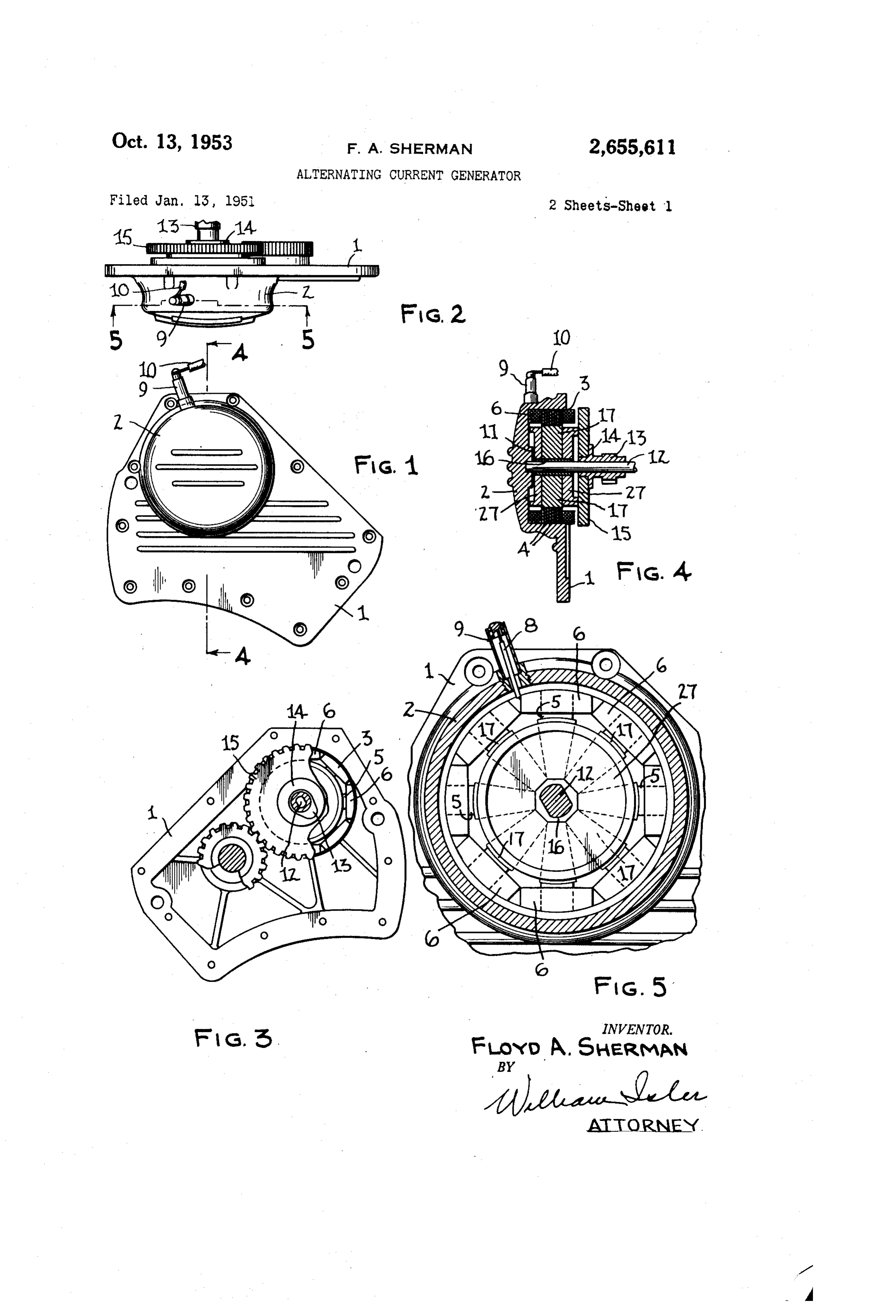
This invention relates, as indicated, to an Referring more particularly to the drawings, alternating current generator, but has reference I have shown a generator which I have designed more particularly to a novel construction of rotor particularly for use in generating the current for such a generator, and to a method of making required for certain purposes on a gasoline engine said rotor. driven bicycle, but it is to be understood that A primary object of the invention is to provide the generator has a much wider range of ap a rotor of the character described, through the plication or use than this specific application. use of which a magnetic field of maximum effir In the drawings, reference numeral repre ciency is obtainable, with the Smallest possible Sents the generator housing side plate, preferably O made in the form of an aluminum casting, having diameter of the rotor.
Another object of the invention is to provide a cylindrical protuberance 2 forming a housing a rotor of the character described, of extremely for portions of the generator to be presently simple construction, consisting of parts which described.
can be quickly and inexpensively cast, and easily Disposed within the protuberant portion 2 of assembled to form a unitary structure, the con the Side plate is a stator ring 3, which consists ponent portions of which are effectively locked of a Series of laminations 4 of annular form, against displacement from each other. having a multiplicity of circumferentially-spaced, A further object of the invention is to provide radially-in Wardly extending poles S. For the a novel method of assembling or making the Special purposes of the present invention, these aforesaid rotor. laminations are preferably stamped or molded Other objects and advantages of my invention from pure iron, as for example, the type of iron will be apparent during the course of the fol commonly known as Armco ingot iron. lowing description. In the accompanying draw Coils 6 are wound around each of the poles 5, ings forming a part of this Specification and in and these coils are suitably electrically insulated which like numerals are employed to designate from each other, as well as from the stator in like parts throughout the Same, any Well-known manner, which need not be Fig. 1 is a side elevational view of the gener described, varnished insulating papers being gen ator, showing the generator housing Side plate; erally available for this purpose. In this par Fig. 2 is a top plan view of the generator and ticular case, the coils 6, as shown in Fig. 11, are side plate; connected in series with each other, one terminal Fig. 3 is a side elevational view of the side of of the connecting wire being grounded to the the generator and housing reverse to that shown housing ?, and the other terminal 8 of the con in Fig. 1; hecting wire extending through a terminal Fig. 4 is a fragmentary cross-sectional view, housing 9 which extends radially from the por taken on the line 4-4 of Fig. 1; tion 2 of the side plate. - Fig. 5 is a fragmentary cross-sectional view, A wire to is connected to the terminal 8 and taken on the line 5-5 of Fig. 2; Supplies current for the operation of various Fig. 6 is a front elevational view of the rotor accessories, such for example, as the head lamp, of the generator, showing the magnet retaining tail lamp, ignition system for the gasoline engine, ring in operative position; horn and radio. This series arrangement of the Fig. 7 is a cross-sectional view taken on the generator coils is designed for a constant load line. T-7 of Fig. 6; requirement.
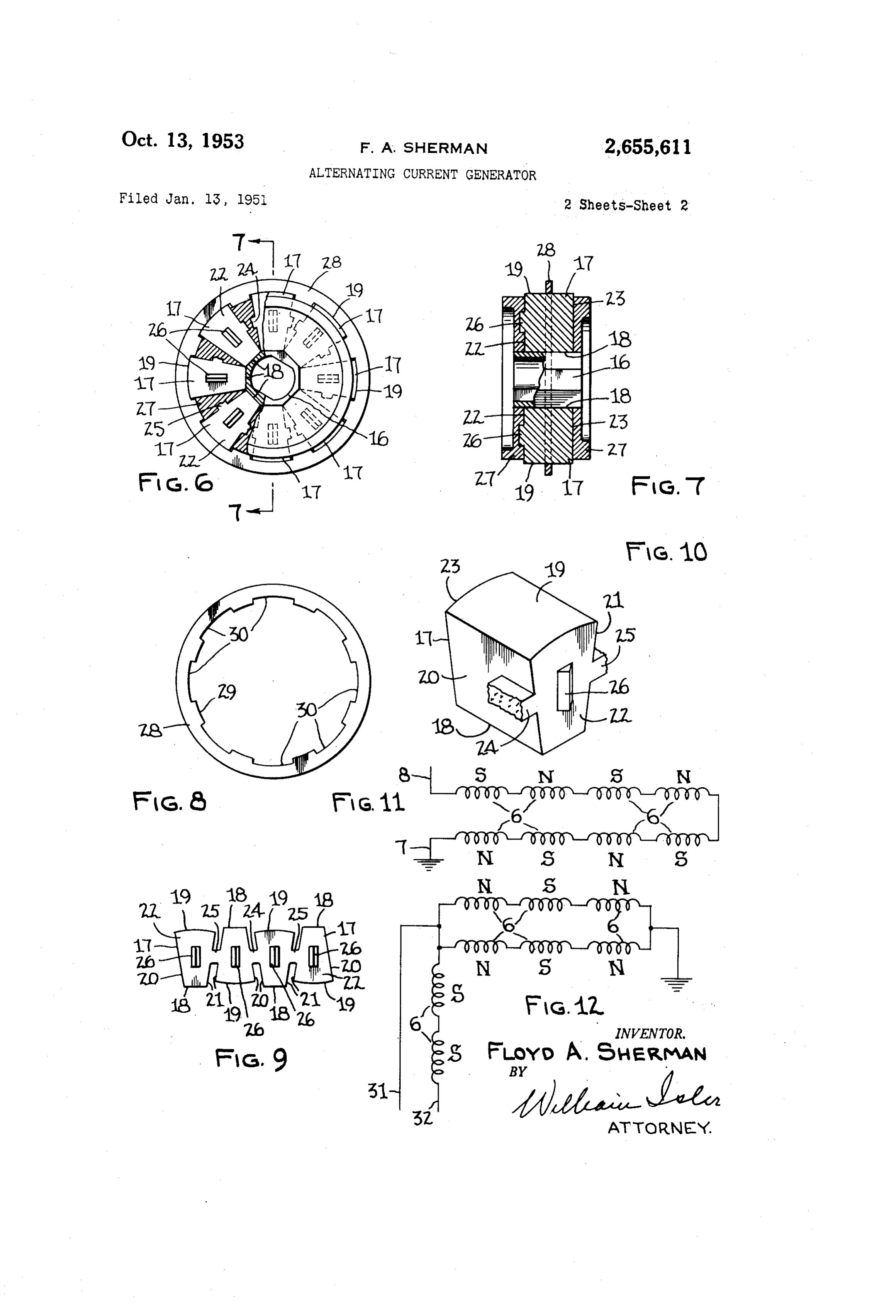
Fig. 8 is a front elevational view of the magnet The casting forming the housing side plate is retaining ring; also provided centrally of the protuberance 2 Fig. 9 is an elevational view showing the pre With a hub fl, in which is journalled one end of a shaft 2, which extends axially through the ferred multiple or group form in which the magnets are cast; stator housing and has rigidly secured thereto Fig. 10 is a perspective view, showing a single a can shaft 3 provided with an annular fiange magnet; 4. Which abuts one face of a timing gear 5 Fig. 11 is a diagram showing the arrangement which is keyed or otherwise non-rotatably se of the generator coils under certain conditions cured to the camshaft 3.
of use of the generator, and Secured on the shaft t2, between the hub Fig. 12 is a diagram showing the arrangement and timing gear 5, is the generator rotor, which of the generator coils for another condition of comprises a core f6 of octagonal external cross use of the generator. 5 Section. This core...is preferably made from com
Page 4
pressed powdered metal, the preferred analysis The rotor which has been described has been being that of SAE 1018 H. R. Steel. designed especially with a view to obtaining the The rotor further comprises a multiplicity of most efficient magnetic field possible, with the magnetic pole-pieces or magnets il, each magnet Smallest possible diameter. being wedge-shaped, and having a radially-in i By using pure iron, or an equivalent metal or Ward fiat face or base 8 in contact With One alloy as the stator of the generator or alternator, of the flat outer faces of the core 16, a radially and with the electrical field which has been de outer face 9 of arcuate cross-section in a di scribed, I am able to control the voltage, under rection circumferentially of the rotor, converging load, of the generator, irrespective of any in side faces 20 and 2, and parallel flat front and ( crease in the generator shaft Speed. rear Walls or faces 22 and 23. The present generator, for example, has a shaft The faces 2G and 2 are respectively provided speed which may vary from 500 to 3000 R. P. M. with protuberant lugs 24 and 25 which extend The voltage developed by the generator under substantially parallel with the base 8 and from these varying speed conditions does not drop be the front face 22 to a point Substantially midway 5 low 6 volts and does not exceed .2 volts. With between the faces 22 and 23. The face 22 is the rotor which has been described, magnetic flux provided with a third lug or protuberance 26 of reversals of approximately 66 per second are de V-shaped cross-section extending centrally along Veioped by the generator, So that the Steel Se the face 22 and radially with respect to the rotor lected must be reluctant to flux reversals of Over as a Whole. The lug or protuberance 26 is also 66 of a second in duration. The coils of the disposed midway between the faces 8 and 9 stator are designed to carry the required current, of the magnet. The lugs 24, 25 and 26 serve a which will also set up eddy currents in the sta purpose to be now described. tor Steel. When the speed of the generator Shaft The magnets , of which there are eight in increases, the Voltage and fl'equency also in number, corresponding to the number of poles 5 2 crease, but as the steel stator 'eceives this in of the stator, are preferably made from a highly creasing frequency, it sets up stronger eddy cul magnetic alloy, known at AlmCO WI. l'ents, SuppleSSing Ol' conti'olling the Voltage. The magnets are permanently maintained in The frequency of this generator, at top speed of proper circumferentially spaced relation to each 3000 R. P. M., is approximately 200 cycles per sec other and in contact with the fiat faces of the 3) Ond.
core 6 by means of a cage 27, formed by die cast In Fig. 12, I have shown a modified arrange ing metal, as for example, Alcoa's 85X or Feder Iilent Of the coils , in which the terminal 3 is ated F430. This cage not only fills the SpaceS be connected to an intermittent heavy load, such as tween the magnets 7, but also covers the front the horn or radio, and the terminal 32 is con and rear faces, 22 and 23, of each magnet. S is5 nected to a constant light load, such as the head In order to maintain the magnets in assembled lamp, tail lamp and ignition system. relation with the core 6 during the proceSS of It is to be understood that the form and con pouring the cage 27, i. e., aSSembling the rotor, Struction of the roto", and the method of assem a sheet metal magnet retaining ling 28 is pro ling or nanufacturing Same, herein shown and vided, which is disposed about the magnetS in described, are to be tatken as preferred exam the manner shown in Fig. 6. ihe ring 28 has ples, and that various changes in the shape, size formed in its inner peripheral edge 29 a nulti and arrangement of parts, and in the steps of plicity of uniformly spaced shallow receSSes 3, manufacturing and assembling same, may be re equivalent in number to the number of magnets Sorted to, without departing from the spirit of f7 and of a length. Substantially the Same aS my invention, or the Scope of the subjoined the length of the faces 9 of the magnets, these claims.
recesses receiving the outer peripheral portions Having thus described my invention, I claim: of the magnets. The ring 28 thus functions to 1. The method of making a rotor of the chair retain the magnetS in properly aSSembled rela acter described, Said method comprising the steps tion, both with respect to each other and with of providing a central core, arranging poles in respect to the core 6, during the pouring of circumferentially-spaced relation and in abut the cage or matrix 27. ment With Said core, retaining said poles in said After the cage 2: has been cast, and has solidi relation by means of a one-piece retaining ring fied, the retaining ring 23, which is no longer re embracing the radially-outermost faces of said quired, may be easily slipped off the assembled poles and renovable from said poles by axial rotor by a sinple axiai movement thereof. movement from the poles, pouring a non-mag During the casting of the cage 27, the lugs 24, netic metal in the interstices between said poles 25 and 25 become embedded in the material of and against the front and rear faces of the poles the cage, and are thus effective to prevent dis placement of the inagnets both circumferentially 6) to permanently retain said poles in said relation, and removing said retaining ring by axial move and radially With respect to the cage during han ment from the poles after said non-magnetic dling and use of the rotor. metal has solidified, the axial length of said re For convenience in casting the magnets and at taining ring being very small in relation to the the same time providing thein with the lugs 24 axial length of said pole faces, whereby ot facil and 25, they may b3 cast in groups of multiples itate removal of the retaining ring by said axial of four, connected together, as shown in Fig. 9. movement.
This also facilitates Shipping. Upon arrival at 2. In an alternating current generator of the the asserabling Station, they are broken apart, character described, a permanent magnet rotor S0 that the connecting webs or sprues form the comprising a casting of non-magnetic material lugs of the individual magnets. having end faces normal to the axis of the rotor, The faces 9 of the magnets extend tthrough a central core, the ends of which are substantially an arc which is Somewhat longer than the arc flush With the end faces of the casting, and a plu of the faces of the poles 5, this arc being approx rality of circumferentially-spaced magnets em imately the same as the arcuate distances be bedded in Said casting and extending radially tween the radially-innermost ends of the poles 5. S outwardly from Said core through said casting,
Page 5
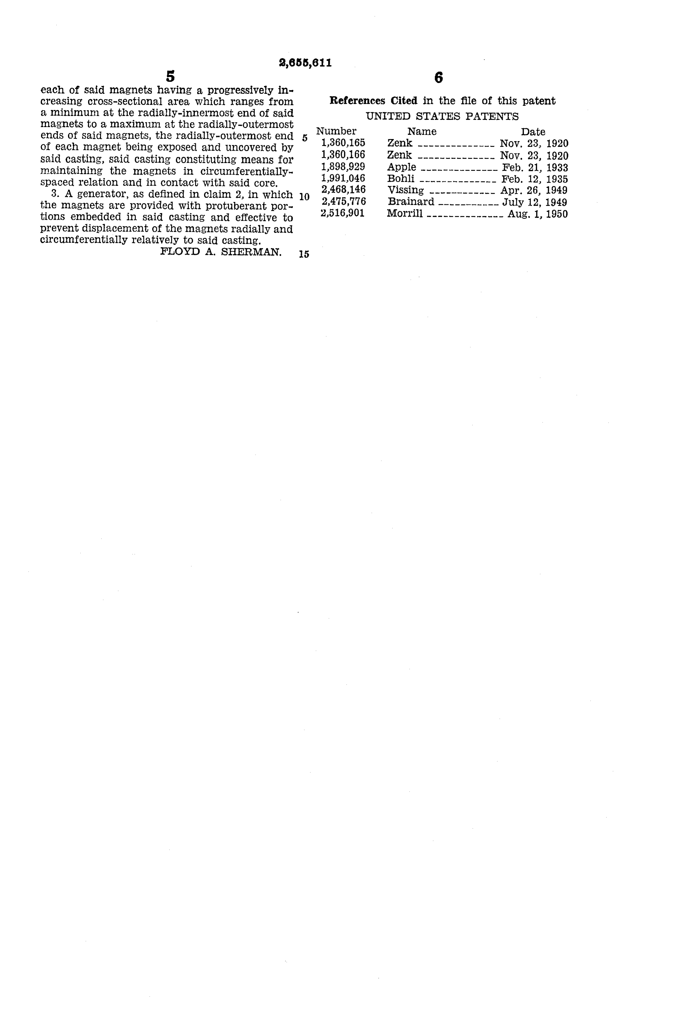
each of said magnets having a progressively in creasing cross-sectional area, which ranges from References Cited in the file of this patent a minimum at the radially-innermost end of said UNITED STATES PATENTS magnets to a maximum at the radially-outermost ends of said magnets, the radially-outermost end 5 Number Name Date of each magnet being exposed and uncovered by 1,360,165 Zenk -------------- Nov. 23, 1920 said casting, said casting constituting means for 1,360,166 Zenk -------------- Nov. 23, 1920 maintaining the magnetS in circumferentially 1898,929 Apple -------------- Feb. 21, 1933 Spaced relation and in contact with said core. 1991,046 Bohli -------------- Feb. 12, 1935 3. A generator, as defined in claim 2, in which 10 2,468,146 Vissing ------------ Apr. 26, 1949
the magnets are provided with protuberant por 2,475,776 tions embedded in said casting and effective to 2,516,901 Morrill -------------- Aug. 1, 1950 prevent displacement of the magnets radially and circumferentially relatively to said casting.
Provenance
- Collection
- Cited prior art
- Original PDF
- patentimages.storage.googleapis.com →
- Filed
- 1951-01-13
- Pages
- 5
- Method
- pdftotext (the PDF's own text layer) + pdftoppm 300dpi page scans
- Source
- Google Patents bibliographic record
- Granted
- 1953-10-13
- Inventors
- Floyd A Sherman; WHIZZER MOTOR Co
- Transcribed from
- patentimages.storage.googleapis.com →