patent · US5894183
Permanent magnet generator rotor
13 April 1999
Page 1 — bibliographic record
United States Patent 19 11 Patent Number: 5,894.183
Borchert 45 Date of Patent: Apr. 13, 1999
54 PERMANENT MAGNET GENERATOR 4,393,320 7/1983 Anderson ................................ 310,156
ROTOR
Primary Examiner-Clayton LaBalle
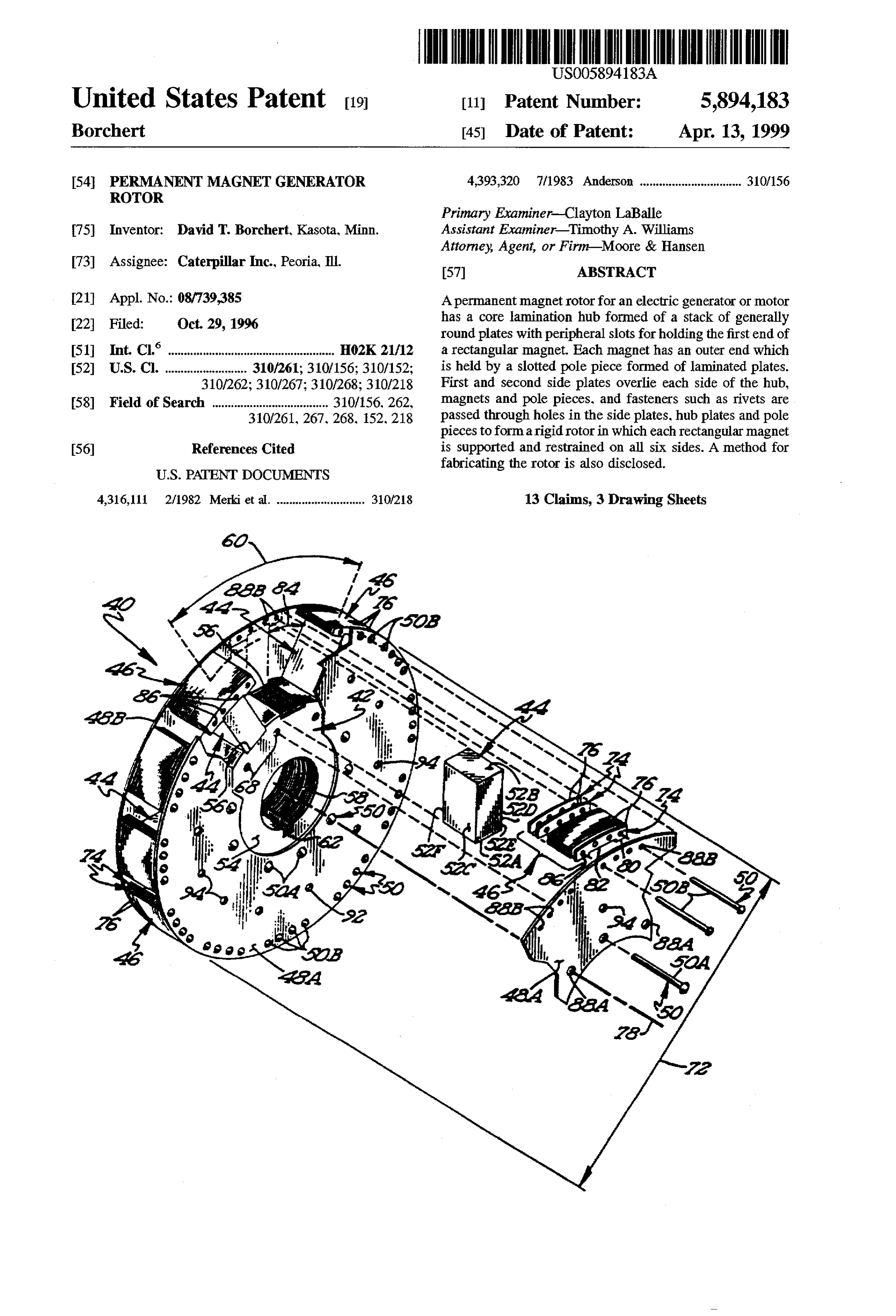
T5 Inventor: David T. Borchert, Kasota, Minn. Assistant Examiner Timothy A. Williams Attorney, Agent, or Firm-Moore & Hansen 73) Assignee: Caterpillar Inc., Peoria, Ill. 57 ABSTRACT 21 Appl. No.: 08/739,385 A permanent magnetrotor for an electric generator or motor 1a. has a core lamination hub formed of a stack of generally 22 Filed: Oct. 29, 1996 round plates with peripheral slots for holding the first end of (51 Int. Claim. HO2K 21/12 a rectangular magnet. Each magnet has an outer end which 52 U.S. Cl. ......................... 310,261; 310/156; 310/152; is held by a slotted pole piece formed of laminated plates. 310/262; 310/267; 310/268; 310/218 First and second side plates overlie each side of the hub, 58) Field of Search ..................................... 310/156.262, magnets and pole pieces, and fasteners such as rivets are 310,261,267,268, 152,218 passed through holes in the side plates, hub plates and pole pieces to formarigid rotor in which each rectangular magnet 56 References Cited is Supported and restrained on all six sides. A method for fabricating the rotor is also disclosed.
4,316,11 2/1982 Merki et al. ............................ 310/28 13 Claims, 3 Drawing Sheets
Page 2
Drawing sheet — no readable text.
Page 3
Drawing sheet — no readable text.
Page 4
Drawing sheet — no readable text.
Page 5
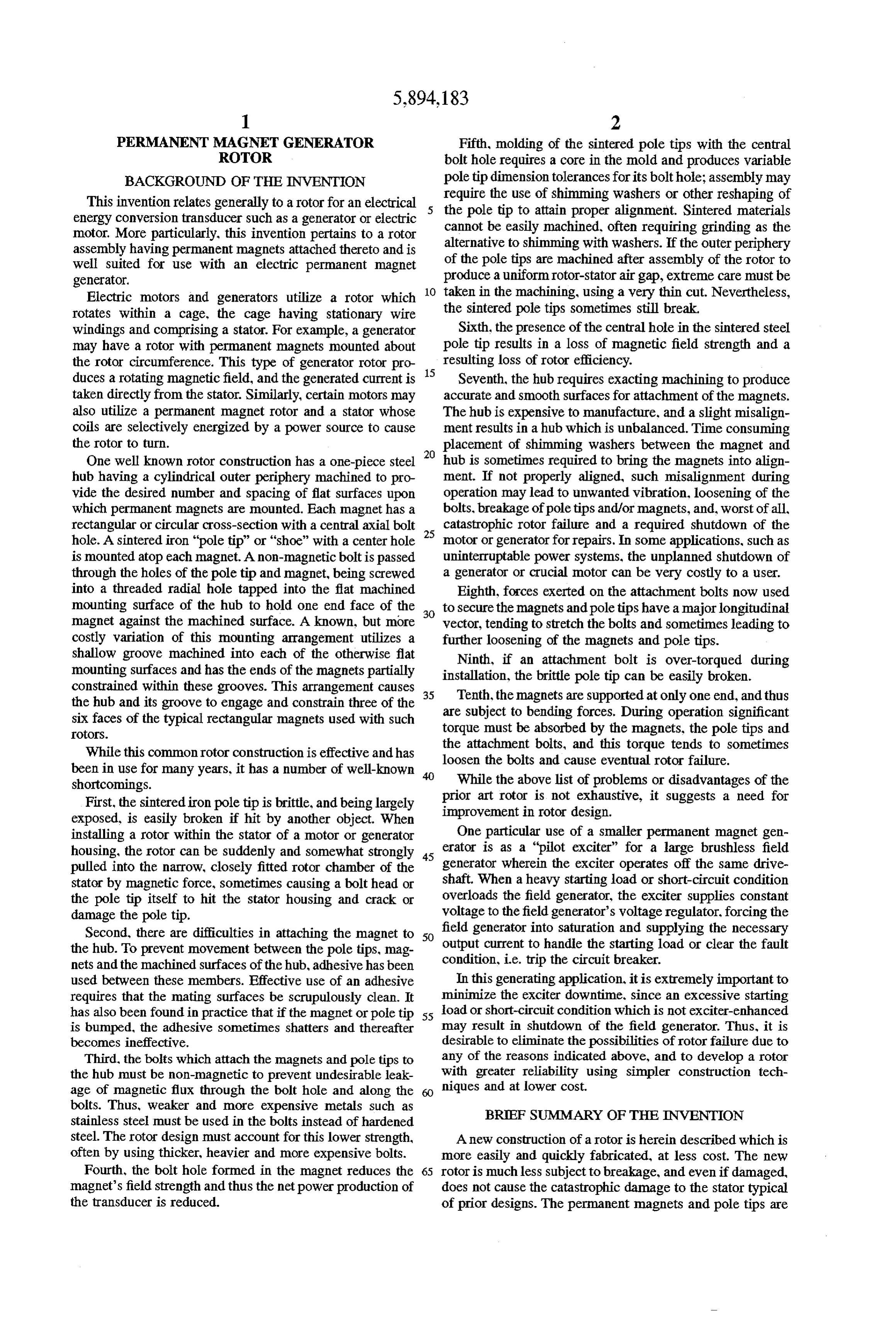
PERMANENT MAGNET GENERATOR Fifth, molding of the sintered pole tips with the central ROTOR bolt hole requires a core in the mold and produces variable BACKGROUND OF THE INVENTION pole tip dimension tolerances for its bolt hole; assembly may require the use of shimming washers or other reshaping of
This invention relates generally to a rotor for an electrical 5 the energy conversion transducer such as a generator or electric pole tip to attain proper alignment. Sintered materials motor. More particularly, this invention pertains to a rotor cannot be easily machined, often requiring grinding as the assembly having permanent magnets attached thereto and is alternative to shimming with washers. If the outer periphery well suited for use with an electric permanent magnet of the pole tips are machined after assembly of the rotor to generator. produce a uniform rotor-stator air gap, extreme care must be Electric motors and generators utilize a rotor which 10 taken in the machining, using a very thin cut. Nevertheless, rotates within a cage, the cage having stationary wire the sintered pole tips sometimes still break. windings and comprising a stator. For example, a generator Sixth, the presence of the central hole in the sintered steel may have a rotor with permanent magnets mounted about pole tip results in a loss of magnetic field strength and a the rotor circumference. This type of generator rotor pro 15 resulting loss of rotor efficiency.
duces a rotating magnetic field, and the generated current is Seventh, the hub requires exacting machining to produce taken directly from the stator. Similarly, certain motors may accurate and smooth surfaces for attachment of the magnets. also utilize a permanent magnet rotor and a stator whose The hub is expensive to manufacture, and a slight misalign coils are selectively energized by a power source to cause ment results in a hub which is unbalanced. Time consuming the rotor to turn. placement of shimming washers between the magnet and One well known rotor construction has a one-piece steel 20 hub is sometimes required to bring the magnets into align hub having a cylindrical outer periphery machined to pro ment. If not properly aligned, such misalignment during vide the desired number and spacing of flat surfaces upon operation may lead to unwanted vibration, loosening of the which permanent magnets are mounted. Each magnet has a bolts, breakage of pole tips and/or magnets, and, worst of all, rectangular or circular cross-section with a central axial bolt catastrophic rotor failure and a required shutdown of the hole. A sintered iron "pole tip” or "shoe" with a center hole 25 motor or generator for repairs. In some applications, such as is mounted atop each magnet. A non-magnetic bolt is passed uninterruptable power systems, the unplanned shutdown of through the holes of the pole tip and magnet, being screwed a generator or crucial motor can be very costly to a user. into a threaded radial hole tapped into the flat machined Eighth, forces exerted on the attachment bolts now used mounting surface of the hub to hold one end face of the to secure the magnets and pole tips have a major longitudinal magnet against the machined surface. A known, but more vector, tending to stretch the bolts and sometimes leading to costly variation of this mounting arrangement utilizes a further loosening of the magnets and pole tips. shallow groove machined into each of the otherwise flat Ninth, if an attachment bolt is over-torqued during mounting surfaces and has the ends of the magnets partially installation, constrained within these grooves. This arrangement causes 35 Tenth, the the brittle pole tip can be easily broken. the hub and its groove to engage and constrain three of the are subject to bendingareforces.
magnets supported at only one end, and thus six faces of the typical rectangular magnets used with such torque must be absorbed by theDuring operation significant magnets, the pole tips and
OtOS.
While this common rotor construction is effective and has the attachment bolts, and this torque tends to sometimes loosen the bolts and cause eventual rotor failure.
been in use for many years, it has a number of well-known While the above list of problems or disadvantages of the shortcomings.
First, the sintered iron pole tip is brittle, and being largely prior art rotor is not exhaustive, it suggests a need for improvement in rotor design.
exposed, is easily broken if hit by another object. When installing a rotor within the stator of a motor or generator One particular use of a smaller permanent magnet gen housing, the rotor can be suddenly and somewhat strongly 45 erator is as a "pilot exciter” for a large brushless field pulled into the narrow, closely fitted rotor chamber of the generator wherein the exciter operates off the same drive stator by magnetic force, sometimes causing a bolt head or shaft. When a heavy starting load or short-circuit condition the pole tip itself to hit the stator housing and crack or overloads the field generator, the exciter supplies constant damage the pole tip. voltage to the field generator's voltage regulator. forcing the Second, there are difficulties in attaching the magnet to 50 field generator into saturation and supplying the necessary the hub. To prevent movement between the pole tips, mag output current to handle the starting load or clear the fault nets and the machined surfaces of the hub, adhesive has been condition, i.e. trip the circuit breaker. used between these members. Effective use of an adhesive In this generating application, it is extremely important to requires that the mating surfaces be scrupulously clean. It minimize the exciter downtime. Since an excessive starting has also been found in practice that if the magnet or pole tip 55 load or short-circuit condition which is not exciter-enhanced is bumped, the adhesive sometimes shatters and thereafter may result in shutdown of the field generator. Thus, it is becomes ineffective. desirable to eliminate the possibilities of rotor failure due to Third, the bolts which attach the magnets and pole tips to any of the reasons indicated above, and to develop a rotor the hub must be non-magnetic to prevent undesirable leak with greater reliability using simpler construction tech age of magnetic flux through the bolt hole and along the niques and at lower cost.
bolts. Thus, weaker and more expensive metals such as BRIEF SUMMARY OF THE INVENTION stainless steel must be used in the bolts instead of hardened steel. The rotor design must account for this lower strength, A new construction of a rotor is herein described which is often by using thicker, heavier and more expensive bolts. more easily and quickly fabricated, at less cost. The new Fourth, the bolt hole formed in the magnet reduces the 65 rotor is much less subject to breakage, and even if damaged, magnet's field strength and thus the net power production of does not cause the catastrophic damage to the stator typical the transducer is reduced. of prior designs. The permanent magnets and pole tips are
Page 6
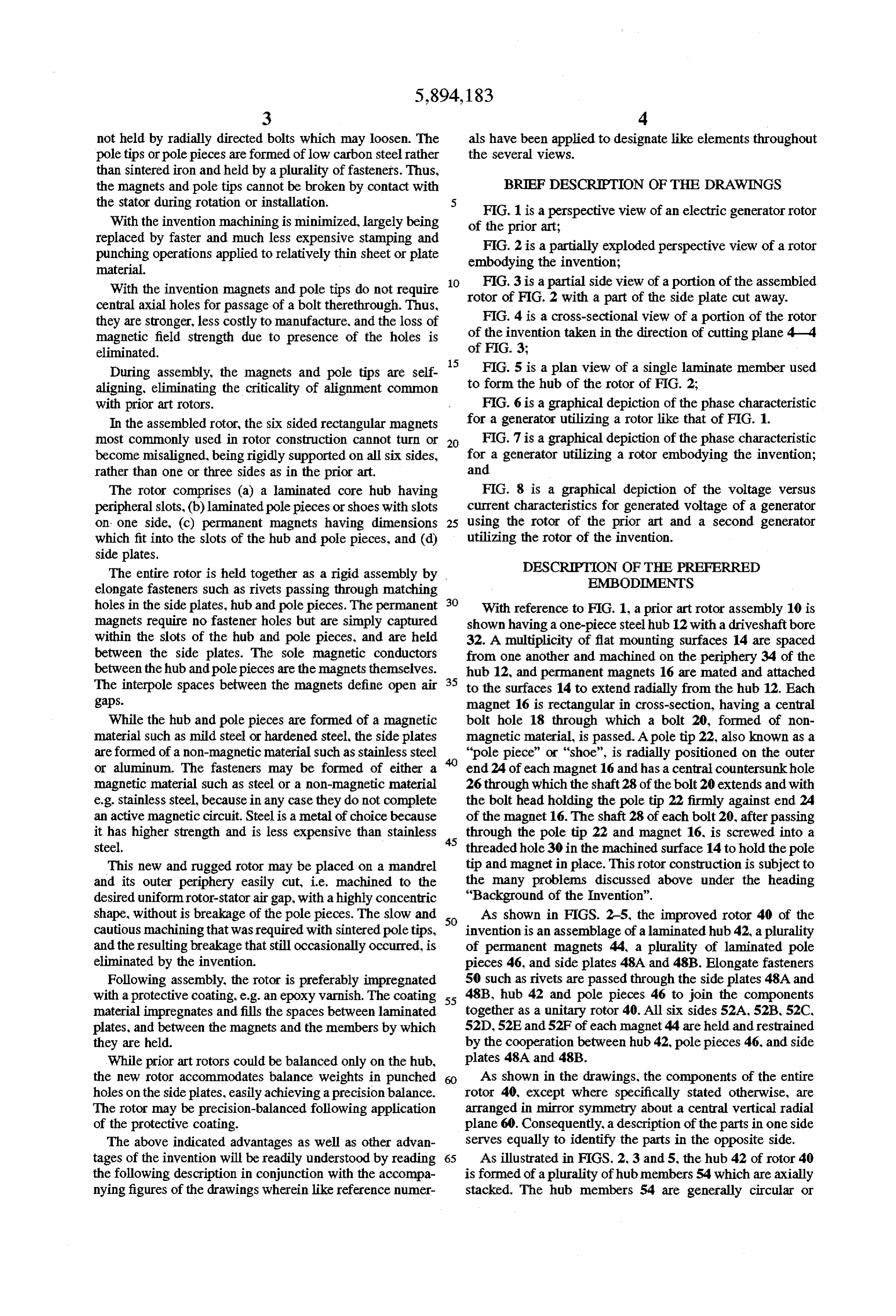
not held by radially directed bolts which may loosen. The als have been applied to designate like elements throughout pole tips or pole pieces are formed of low carbon steel rather the several views.
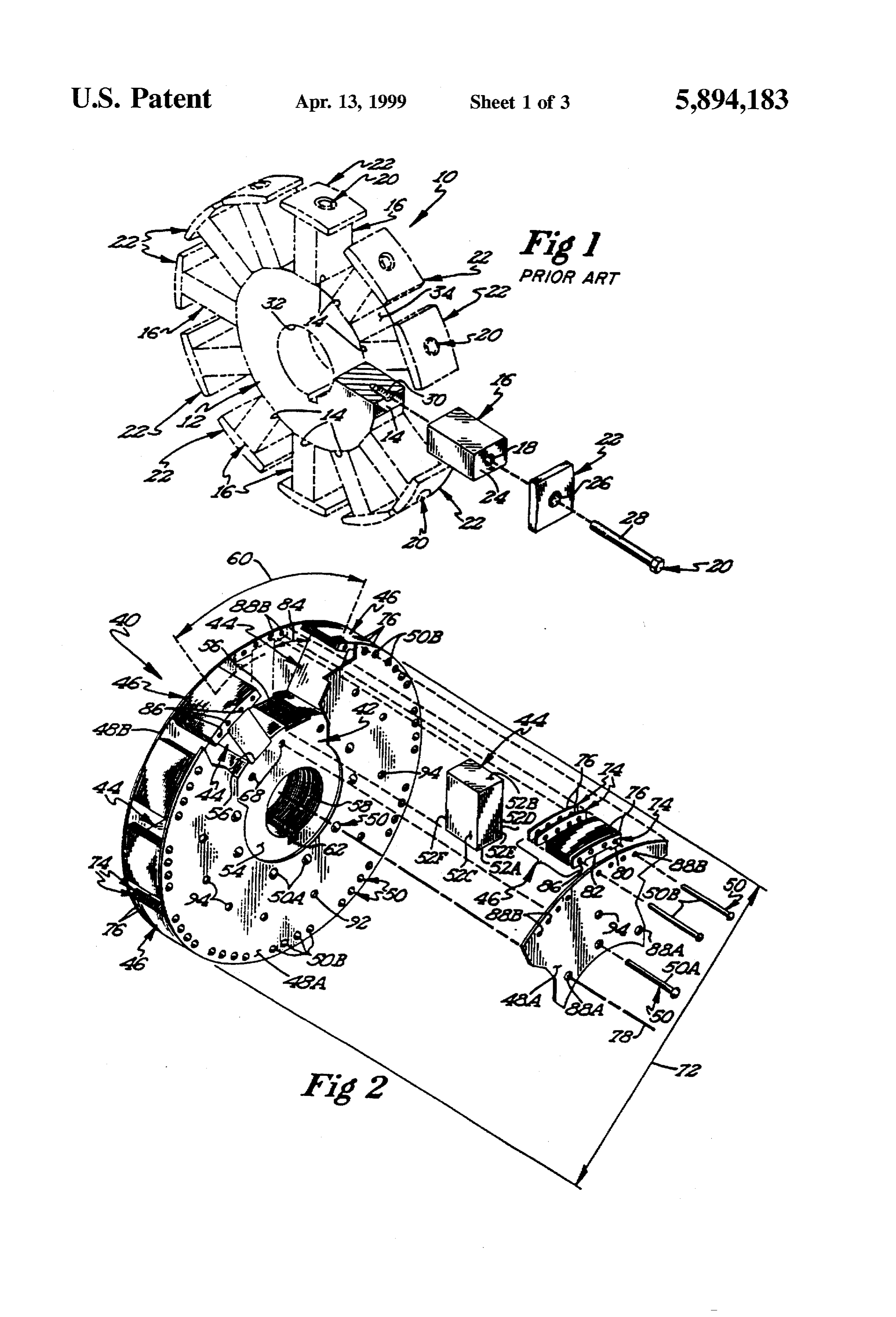
than sintered iron and held by a plurality of fasteners. Thus, the magnets and pole tips cannot be broken by contact with BRIEF DESCRIPTION OF THE DRAWINGS the stator during rotation or installation. FIG. 1 is a perspective view of an electric generator rotor With the invention machining is minimized, largely being of the prior art;
replaced by faster and much less expensive stamping and FIG. 2 is a partially exploded perspective view of a rotor punching operations applied to relatively thin sheet or plate embodying the invention;
material.
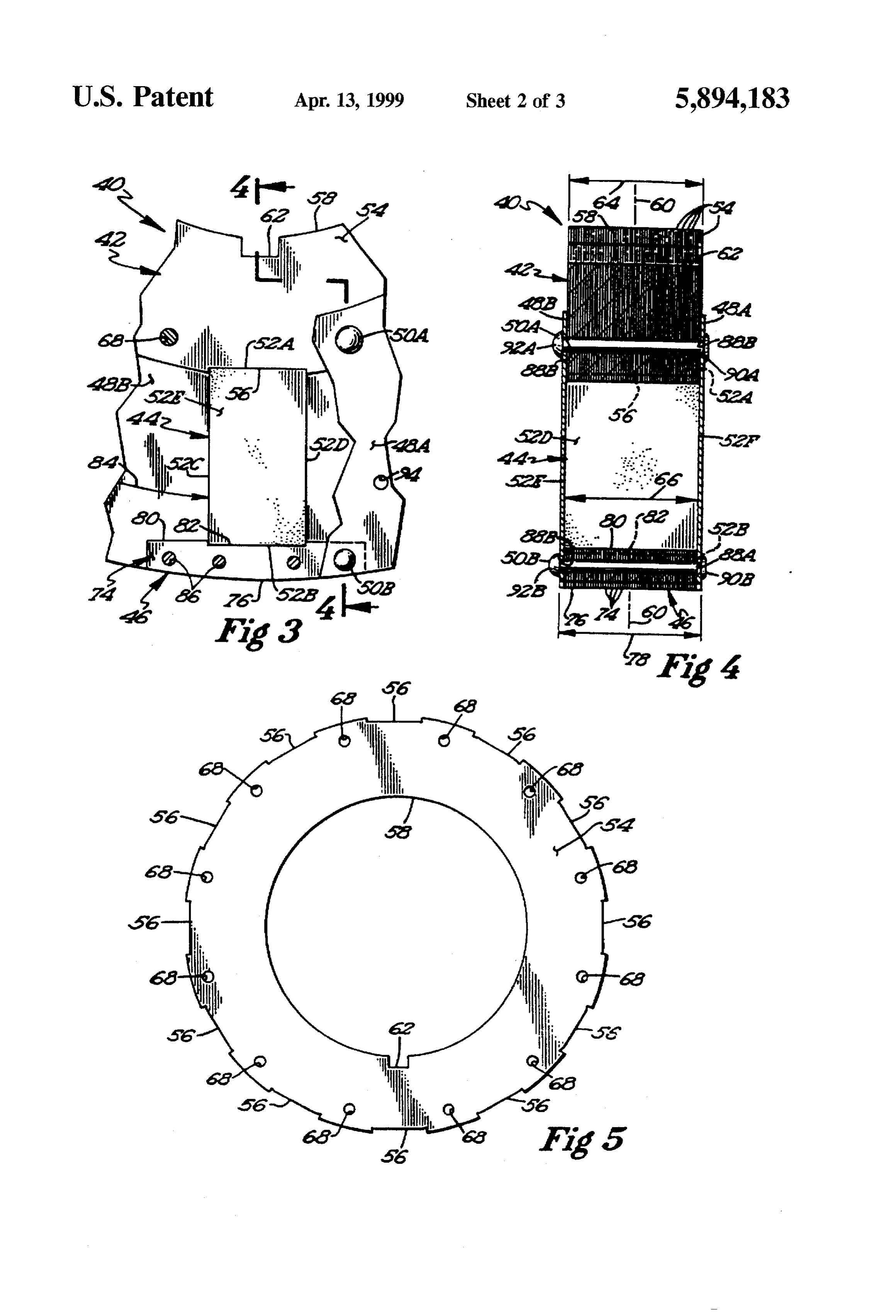
FIG. 3 is a partial side view of a portion of the assembled
With the invention magnets and pole tips do not require 10 rotor central axial holes for passage of a bolt therethrough. Thus, of FIG. 2 with a part of the side plate cut away. they are stronger, less costly to manufacture, and the loss of FIG. 4 is a cross-sectional view of a portion of the rotor magnetic field strength due to presence of the holes is of the invention taken in the direction of cutting plane 4-4 eliminated. of FIG. 3;
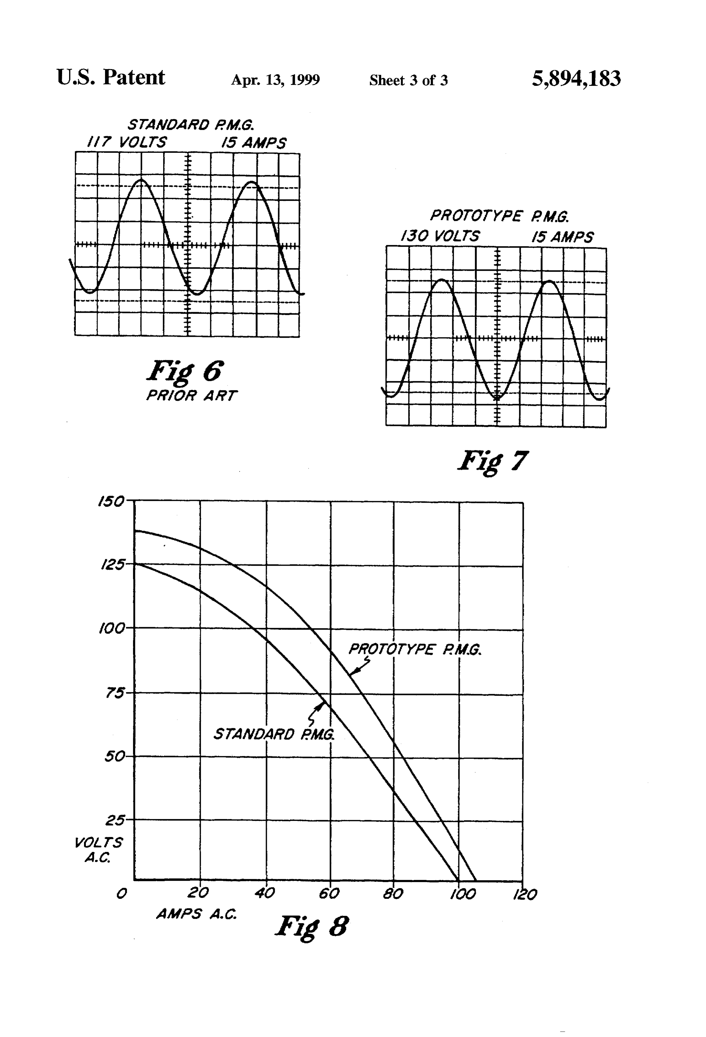
During assembly, the magnets and pole tips are self FIG. 5 is a plan view of a single laminate member used aligning, eliminating the criticality of alignment common to form the hub of the rotor of FIG. 2; with prior art rotors. F.G. 6 is a graphical depiction of the phase characteristic In the assembled rotor, the six sided rectangular magnets for a generator utilizing a rotor like that of FIG. 1. most commonly used in rotor construction cannot turn or 20 FIG. 7 is a graphical depiction of the phase characteristic become misaligned, being rigidly supported on all six sides, for a generator utilizing a rotor embodying the invention; rather than one or three sides as in the prior art. and
The rotor comprises (a) a laminated core hub having FIG. 8 is a graphical depiction of the voltage versus peripheral slots, (b) laminated pole pieces or shoes with slots current characteristics for generated voltage of a generator on- one side, (c) permanent magnets having dimensions 25 using the rotor of the prior art and a second generator which fit into the slots of the hub and pole pieces, and (d) utilizing the rotor of the invention. side plates.
The entire rotor is held together as a rigid assembly by DESCRIPTION OF THE PREFERRED elongate fasteners such as rivets passing through matching EMBODIMENTS holes in the side plates, hub and pole pieces. The permanent 30 With reference to FIG. 1, a prior art rotor assembly 10 is magnets require no fastener holes but are simply captured shown having a one-piece steel hub 12 with a driveshaft bore within the slots of the hub and pole pieces, and are held 32. A multiplicity of flat mounting surfaces 14 are spaced between the side plates. The sole magnetic conductors from one another and machined on the periphery 34 of the between the hub and pole pieces are the magnets themselves. hub 12, and permanent magnets 16 are mated and attached The interpole spaces between the magnets define open air 35 to the surfaces 14 to extend radially from the hub 12. Each gaps. magnet 16 is rectangular in cross-section, having a central While the hub and pole pieces are formed of a magnetic bolt hole 18 through which a bolt 20, formed of non material such as mild steel or hardened steel, the side plates magnetic material, is passed. A pole tip 22, also known as a are formed of a non-magnetic material such as stainless steel "pole piece" or "shoe", is radially positioned on the outer or aluminum. The fasteners may be formed of either a end 24 of each magnet 16 and has a central countersunkhole magnetic material such as steel or a non-magnetic material 26through which the shaft 28 of the bolt 20 extends and with e.g. stainless steel, because in any case they do not complete the bolt head holding the pole tip 22 firmly against end 24 an active magnetic circuit. Steel is a metal of choice because of the magnet 16. The shaft 28 of each bolt 20, after passing it has higher strength and is less expensive than stainless 45 through the pole tip 22 and magnet 16, is screwed into a steel. threaded hole 30 in the machined surface 14 to hold the pole This new and rugged rotor may be placed on a mandrel tip and magnet in place. This rotor construction is subject to and its outer periphery easily cut, i.e. machined to the the many problems discussed above under the heading desired uniform rotor-stator air gap, with a highly concentric "Background of the Invention".
shape, without is breakage of the pole pieces. The slow and 50 As shown in FIGS. 2-5, the improved rotor 40 of the cautious machining that was required with sintered pole tips, invention is an assemblage of a laminated hub 42, a plurality and the resulting breakage that still occasionally occurred, is of permanent magnets 44, a plurality of laminated pole eliminated by the invention. pieces 46, and side plates 48A and 48B. Elongate fasteners Following assembly, the rotor is preferably impregnated 50 such as rivets are passed through the side plates 48A and with a protective coating, e.g. an epoxy varnish. The coating 55 48B, hub 42 and pole pieces 46 to join the components material impregnates and fills the spaces between laminated together as a unitary rotor 40. All six sides 52A, 52B, 52C, plates, and between the magnets and the members by which 52D, 52E and 52F of each magnet 44 are held and restrained they are held. by the cooperation between hub 42, pole pieces 46, and side While prior art rotors could be balanced only on the hub, plates 48A and 48B.
the new rotor accommodates balance weights in punched As shown in the drawings, the components of the entire holes on the side plates, easily achieving a precision balance. rotor 40, except where specifically stated otherwise, are The rotor may be precision-balanced following application arranged in mirror symmetry about a central vertical radial of the protective coating. plane 60. Consequently, a description of the parts in one side The above indicated advantages as well as other advan serves equally to identify the parts in the opposite side. tages of the invention will be readily understood by reading 65 As illustrated in FIGS. 2, 3 and 5, the hub 42 of rotor 40 the following description in conjunction with the accompa is formed of a plurality of hub members 54 which are axially nying figures of the drawings wherein like reference numer stacked. The hub members 54 are generally circular or
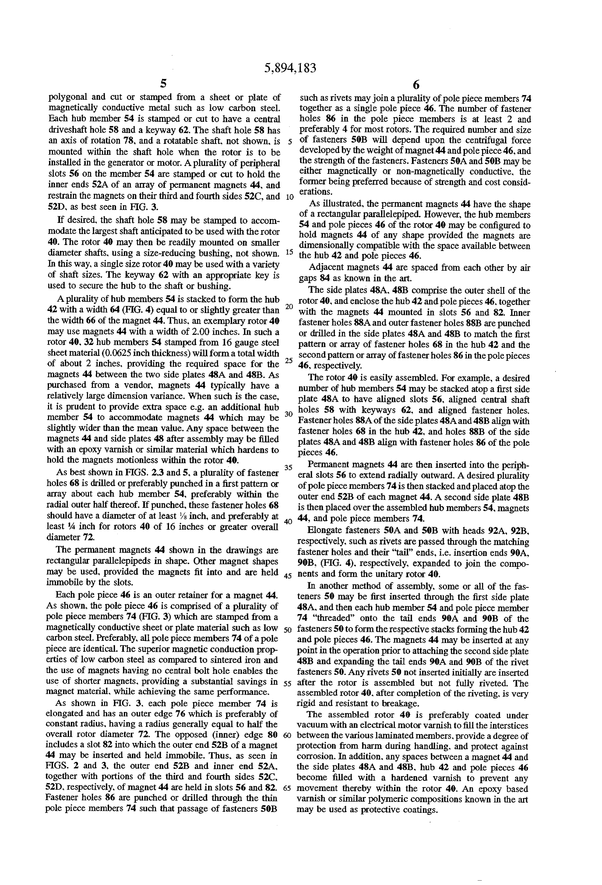
Page 7
S 6 polygonal and cut or stamped from a sheet or plate of such as rivets may join a plurality of pole piece members 74 magnetically conductive metal such as low carbon steel. together as a single pole piece 46. The number of fastener Each hub member 54 is stamped or cut to have a central holes 86 in the pole piece members is at least 2 and driveshaft hole 58 and a keyway 62. The shaft hole 58 has preferably 4 for most rotors. The required number and size an axis of rotation 78, and a rotatable shaft, not shown, is of fasteners 50B will depend upon the centrifugal force mounted within the shaft hole when the rotor is to be developed by the weight of magnet 44 and polepiece 46, and installed in the generator or motor. A plurality of peripheral the strength of the fasteners. Fasteners 50A and 50B may be slots 56 on the member 54 are stamped or cut to hold the either magnetically or non-magnetically conductive, the inner ends 52A of an array of permanent magnets 44, and erations.former being preferred because of strength and cost consid restrain the magnets on their third and fourth sides 52C, and 10 52D, as best seen in FIG. 3. As illustrated, the permanent magnets 44 have the shape If desired, the shaft hole 58 may be stamped to accom 54 aand of rectangular parallelepiped. However, the hub members pole pieces 46 of the rotor 40 may be configured to modate the largest shaft anticipated to be used with the rotor hold magnets 44 of any shape provided the magnets are 40. The rotor 40 may then be readily mounted on smaller dimensionally compatible with the space available between diameter shafts, using a size-reducing bushing, not shown. the hub 42 and pole pieces 46.
In this way, a single size rotor 40 may be used with a variety Adjacent magnets 44 are spaced from each other by air of shaft sizes. The keyway 62 with an appropriate key is gaps 84 as known in the art.
used to secure the hub to the shaft or bushing. The side plates 48A, 48B comprise the outer shell of the A plurality of hub members 54 is stacked to form the hub rotor 40, and enclose the hub 42 and pole pieces 46, together 42 with a width 64 (FIG. 4) equal to or slightly greater than with the magnets 44 mounted in slots 56 and 82. Inner the width 66 of the magnet 44. Thus, an exemplary rotor 40 fastener holes 88A and outerfastener holes 88B are punched may use magnets 44 with a width of 2.00 inches. In such a or drilled in the side plates 48A and 48B to match the first rotor 40, 32 hub members 54 stamped from 16 gauge steel pattern or array of fastener holes 68 in the hub 42 and the sheet material (0.0625 inch thickness) will form a total width second patternor array of fastener holes 86 in the pole pieces of about 2 inches, providing the required space for the 25 46, respectively.
magnets 44 between the two side plates 48A and 48B. As The rotor 40 is easily assembled. For example, a desired purchased from a vendor, magnets 44 typically have a number of hub members 54 may be stacked atop a first side relatively large dimension variance. When such is the case, plate 48A to have aligned slots 56, aligned central shaft it is prudent to provide extra space e.g. an additional hub 30 holes 58 with keyways 62, and aligned fastener holes. member 54 to accommodate magnets 44 which may be Fastenerholes 88A of the side plates 48A and 48B align with slightly wider than the mean value. Any space between the fastener holes 68 in the hub 42, and holes 88B of the side magnets 44 and side plates 48 after assembly may be filled plates 48A and 48B align with fastener holes 86 of the pole with an epoxy varnish or similar material which hardens to pieces 46.
hold the magnets motionless within the rotor 40. 35 Permanent magnets 44 are then inserted into the periph As best shown in FIGS. 2.3 and 5, a plurality of fastener eral slots 56 to extend radially outward. A desired plurality holes 68 is drilled or preferably punched in a first pattern or of pole piece members 74 is then stacked and placed atop the array about each hub member 54, preferably within the outer end 52B of each magnet 44. A second side plate 48B radial outer half thereof. If punched, these fastener holes 68 is then placed over the assembled hub members 54, magnets should have a diameter of at least/s inch, and preferably at 44, and pole piece members 74.
least A inch for rotors 40 of 16 inches or greater overall Elongate fasteners 50A and 50B with heads 92A, 92B, diameter 72. respectively, such as rivets are passed through the matching The permanent magnets 44 shown in the drawings are fastener holes and their "tail' ends, i.e. insertion ends 90A, rectangular parallelepipeds in shape. Other magnet shapes 90B, (FIG. 4), respectively, expanded to join the compo may be used, provided the magnets fit into and are held 45 nents and form the unitary rotor 40.
immobile by the slots. In another method of assembly, some or all of the fas Each pole piece 46 is an outer retainer for a magnet 44. teners 50 may be first inserted through the first side plate As shown, the pole piece 46 is comprised of a plurality of 48A, and then each hub member 54 and pole piece member pole piece members 74 (FIG. 3) which are stamped from a 74 "threaded' onto the tail ends 90A and 90B of the magnetically conductive sheet or plate material such as low 50 fasteners 50 to form the respective stacks forming the hub 42 carbon steel. Preferably, all pole piece members 74 of apole and pole pieces 46. The magnets 44 may be inserted at any piece are identical. The superior magnetic conduction prop point in the operation prior to attaching the second side plate erties of low carbon steel as compared to sintered iron and 48B and expanding the tail ends 90A and 90B of the rivet the use of magnets having no central bolt hole enables the fasteners 50. Any rivets 50 not inserted initially are inserted use of shorter magnets, providing a substantial Savings in 55 after the rotor is assembled but not fully riveted. The magnet material, while achieving the same performance. assembled rotor 40, after completion of the riveting, is very As shown in FIG. 3, each pole piece member 74 is rigid and resistant to breakage.
elongated and has an outer edge 76 which is preferably of The assembled rotor 40 is preferably coated under constant radius, having a radius generally equal to half the vacuum with an electrical motor varnish to fill the interstices overall rotor diameter 72. The opposed (inner) edge 80 between the various laminated members, provide a degree of includes a slot 82 into which the outer end 52B of a magnet protection from harm during handling, and protect against 44 may be inserted and held immobile. Thus, as seen in corrosion. In addition, any spaces between a magnet 44 and FIGS. 2 and 3, the outer end 52B and inner end 52A, the side plates 48A and 48B, hub 42 and pole pieces 46 together with portions of the third and fourth sides 52C, become filled with a hardened varnish to prevent any 52D, respectively, of magnet 44 are held in slots 56 and 82. 65 movement thereby within the rotor 40. An epoxy based Fastener holes 86 are punched or drilled through the thin varnish or similar polymeric compositions known in the art pole piece members 74 such that passage of fasteners 50B may be used as protective coatings.
Page 8
The assembled rotor, as fabricated for a generator in a hub having a central axial hole for mounting on the accordance with this description, has a weight approxi shaft, said hole having a central axis; mately equal to a prior art rotor, yet it provides enhanced a plurality of permanent magnets arrayed about said hub power generation and is less expensive to manufacture. and having inner and outer ends; Most machining operations required by the prior art hub 12 said hub formed as a unitary laminated core from a are eliminated.
The assembled rotor 40 is typically placed in a mandrel stacked plurality of flat metal plates, each said flat and rotated in a machining process to provide the desired metal plate continuously encircling said shaft and hav outer diameter and uniform rotor-stator air gaps for optimum ing an outer periphery;
performance. 10 a plurality of spaced slots in said outer periphery for The rotor 40 may be precision balanced by securing retaining the said inner ends of said permanent mag weights in balance holes 94 formed in the side plates 48A. nets;
48B. a plurality of magnetically conductive pole pieces posi Using a single size of hub members 54 and pole piece tioned On the outer ends of said magnets: and members 74, rotors of different widths, smaller or larger first and second side plates positioned on axially opposing magnets, and a differing numbers of poles may be con sides of said hub, magnets and pole pieces and con structed by simply varying the numbers of hub members, nected to said hub and pole pieces by fasteners. pole piece members, and magnets which are utilized. 2. The rotor of claim 1, further comprising a first pattern EXAMPLE of fastener holes through said hub and side plates for passage 20 therethrough of a first set of said fasteners parallel to said
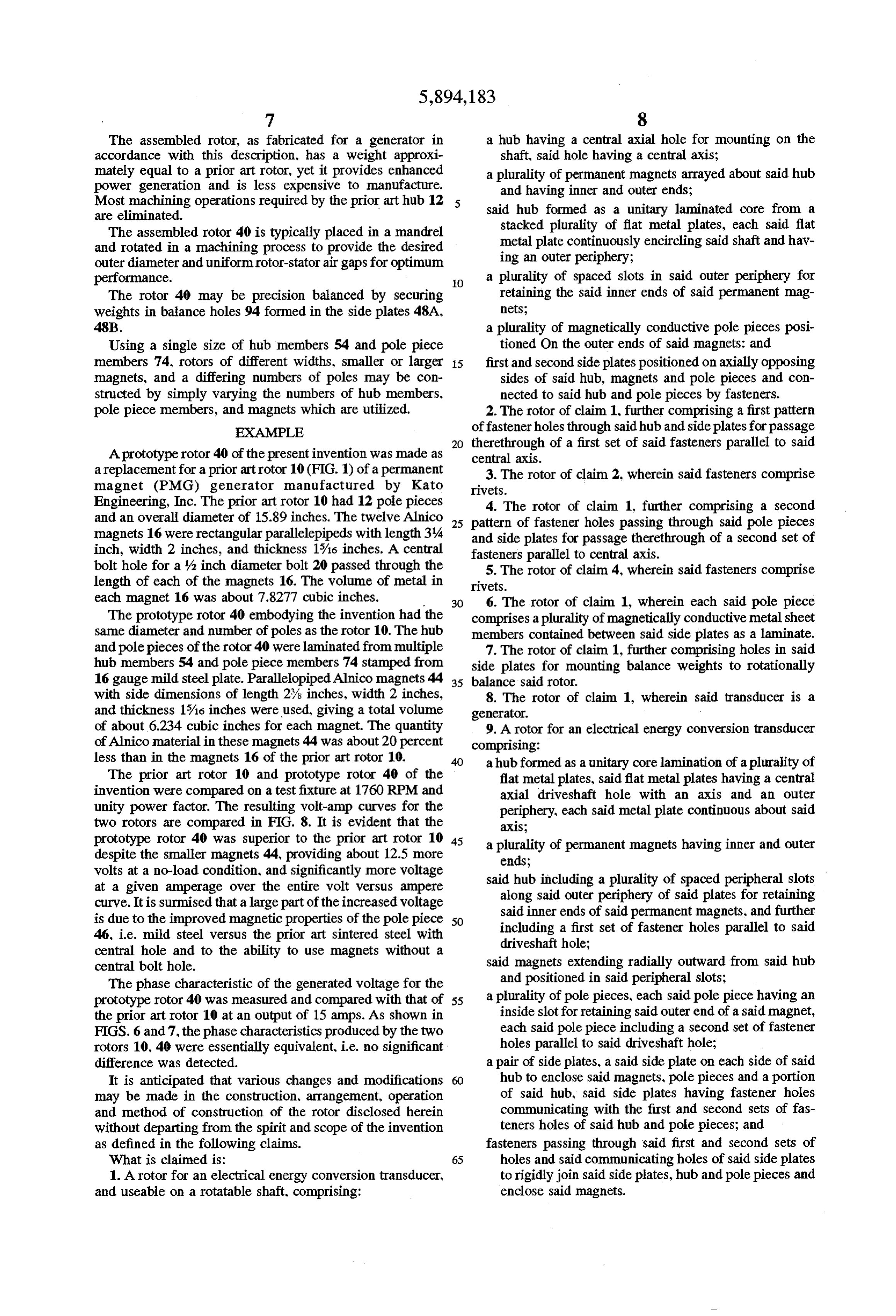
A prototype rotor 40 of the present invention was made as central axis.
a replacement for a prior art rotor 10 (FIG. 1) of a permanent 3. The rotor of claim 2, wherein said fasteners comprise magnet (PMG) generator manufactured by Kato rivets.
Engineering, Inc. The prior art rotor 10 had 12 pole pieces 4. The rotor of claim 1, further comprising a second and an overall diameter of 15.89 inches. The twelve Alnico 25 pattern of fastener holes passing through said pole pieces magnets 16 were rectangular parallelepipeds with length 34 and side plates for passage therethrough of a second set of inch, width 2 inches, and thickness 1%6 inches. A central fasteners parallel to central axis. bolt hole for a y2 inch diameter bolt 20 passed through the 5. The rotor of claim 4, wherein said fasteners comprise length of each of the magnets 16. The volume of metal in rivets.
each magnet 16 was about 7.8277 cubic inches. 30 6. The rotor of claim 1, wherein each said pole piece The prototype rotor 40 embodying the invention had the comprises a plurality of magnetically conductive metal sheet same diameter and number of poles as the rotor 10. The hub members contained between said side plates as a laminate. and pole pieces of the rotor 40 were laminated from multiple 7. The rotor of claim 1, further comprising holes in said hub members 54 and pole piece members 74 stamped from side plates for mounting balance weights to rotationally 16 gauge mild steel plate. Parallelopiped Alnico magnets 44 35 balance said rotor.
with side dimensions of length 2% inches, width 2 inches, 8. The rotor of claim 1, wherein said transducer is a and thickness 1%is inches were used, giving a total volume generator.
of about 6.234 cubic inches for each magnet. The quantity 9. A rotor for an electrical energy conversion transducer of Alnico material in these magnets 44 was about 20 percent comprising:
less than in the magnets 16 of the prior art rotor 10. a hub formed as a unitary core lamination of a plurality of The prior art rotor 10 and prototype rotor 40 of the flat metal plates, said flat metal plates having a central invention were compared on a testfixture at 1760 RPM and axial driveshaft hole with an axis and an outer unity power factor. The resulting volt-amp curves for the periphery, each said metal plate continuous about said two rotors are compared in FIG. 8. It is evident that the aXS.
prototype rotor 40 was superior to the prior art rotor 10 45 a plurality of permanent magnets having inner and outer despite the smaller magnets 44, providing about 12.5 more ends;
volts at a no-load condition, and significantly more voltage said hub including a plurality of spaced peripheral slots at a given amperage over the entire volt versus ampere along said outer periphery of said plates for retaining curve. It is surmised that a large part of the increased voltage said inner ends of said permanent magnets, and further is due to the improved magnetic properties of the pole piece 50 including a first set of fastener holes parallel to said 46, i.e. mild steel versus the prior art sintered steel with driveshaft hole;
central hole and to the ability to use magnets without a central bolt hole. said magnets extending radially outward from said hub The phase characteristic of the generated voltage for the and positioned in said peripheral slots; prototype rotor 40 was measured and compared with that of 55 a plurality of pole pieces, each said pole piece having an the prior art rotor 10 at an output of 15 amps. As shown in inside slot for retaining said outer end of a said magnet, FIGS. 6 and 7, the phase characteristics produced by the two each said pole piece including a second set of fastener rotors 10, 40 were essentially equivalent, i.e. no significant holes parallel to said driveshaft hole; difference was detected. a pair of side plates, a said side plate on each side of said It is anticipated that various changes and modifications hub to enclose said magnets, pole pieces and a portion may be made in the construction, arrangement, operation of said hub, said side plates having fastener holes and method of construction of the rotor disclosed herein communicating with the first and second sets of fas without departing from the spirit and scope of the invention teners holes of said hub and pole pieces; and as defined in the following claims. fasteners passing through said first and second sets of What is claimed is: 65 holes and said communicating holes of said side plates 1. A rotor for an electrical energy conversion transducer, to rigidly join said side plates, hub and pole pieces and and useable on a rotatable shaft, comprising: enclose said magnets.
Page 9
10. The rotor of claim 9, wherein said pole piece com retaining the radially oriented outer end of a permanent prises a plurality of magnetically conductive metal sheet magnet having ends and sides, and a plurality of fastener members joined together as a laminate. holes punched therethrough wherein said sheet members 11. The rotor of claim 9, wherein said elongate fasteners may be mounted as a laminate to define said pole piece, said comprise rivets. slot having sides conformed to generally abut said magnet 12. A pole piece for the rotor of an electrical energy power sides.
conversion transducer with a shaft, comprising a stack of 13. The pole piece of claim 12, wherein the plurality of thin flat sheet members formed of magnetically conductive fastener holes comprises four. material, each said thin sheet member having a substantially constant radius outer periphery, an inner edge with a slot for :: * : * :
Provenance
- Collection
- Cited prior art
- Original PDF
- patentimages.storage.googleapis.com →
- Filed
- 1996-10-29
- Pages
- 9
- Method
- pdftotext (the PDF's own text layer) + pdftoppm 300dpi page scans
- Source
- Google Patents bibliographic record
- Granted
- 1999-04-13
- Inventors
- David T. Borchert; Caterpillar Inc
- Transcribed from
- patentimages.storage.googleapis.com →