patent · US4452046
System for the obtaining of energy by fluid flows resembling a natural cyclone or anti-cyclone
5 June 1984
Page 1 — bibliographic record
United States Patent (19)
Valentin
54 SYSTEM FOR THE OBTAINING OF 4,275,309 6/1981 Lucier .............................. 60/641.12
ENERGY BY FLUID FLOWS RESEMBLNG
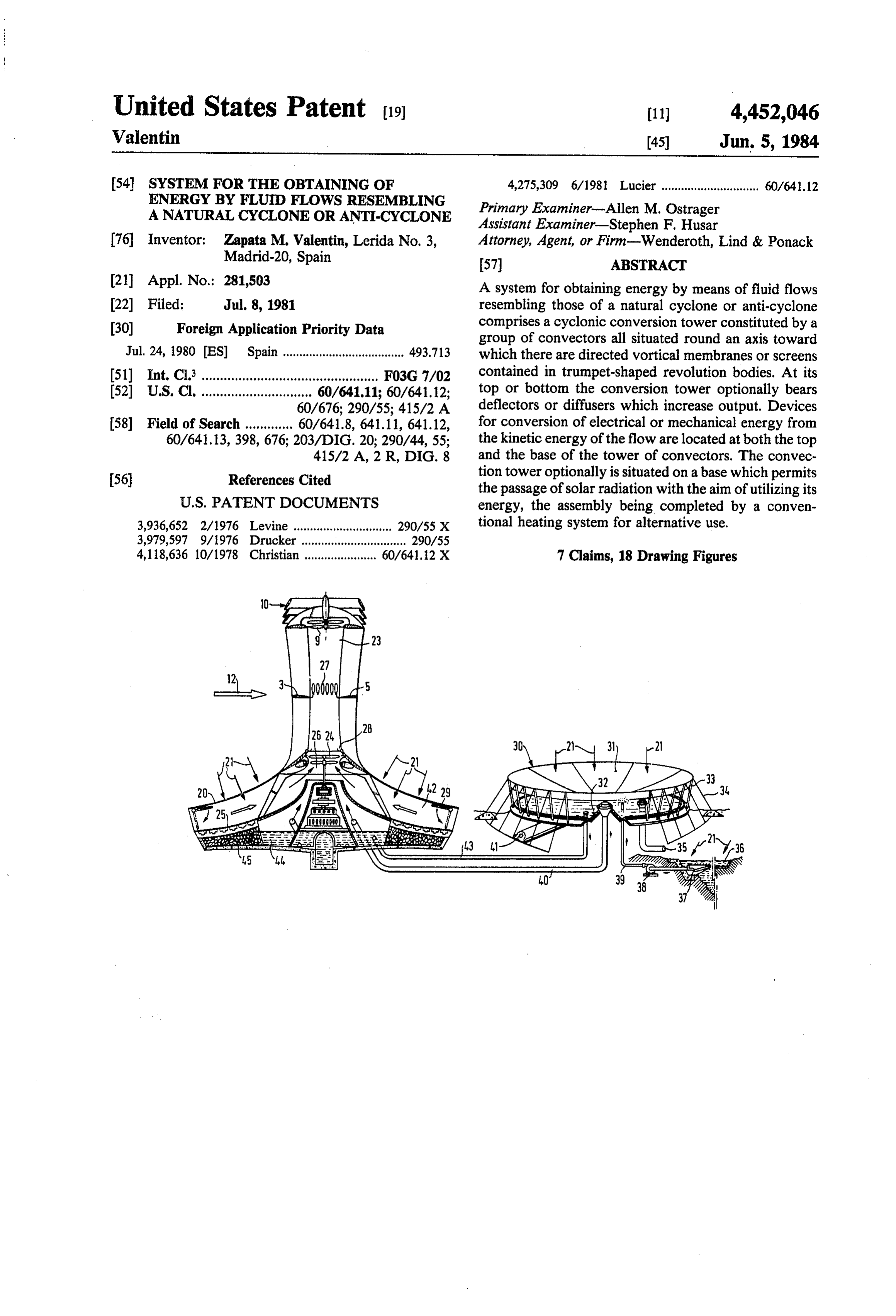
A NATURAL CYCLONE OR ANTI-CYCLONE Primary Examiner-Allen M. Ostrager Assistant Examiner-Stephen F. Husar 76 Inventor: Zapata M. Valentin, Lerida No. 3, Attorney, Agent, or Firm-Wenderoth, Lind & Ponack Madrid-20, Spain 57 ABSTRACT (21) Appl. No.: 281,503 A system for obtaining energy by means of fluid flows (22 Filed: Jul. 8, 1981 resembling those of a natural cyclone or anti-cyclone 30 Foreign Application Priority Data comprises a cyclonic conversion tower constituted by a group of convectors all situated round an axis toward
Jul. 24, 1980 ES Spain..................................... 493.713 which there are directed vortical membranes or screens 51) Int. Cl. ................................................ FO3G 7/02 contained in trumpet-shaped revolution bodies. At its 52 U.S. C. .............................. 60/641.11; 60/641.12; top or bottom the conversion tower optionally bears 60/676; 290/55; 41.5/2 A deflectors or diffusers which increase output. Devices 58) Field of Search ............. 60/641.8, 641.11, 641.12, for conversion of electrical or mechanical energy from 60/641.13,398,676; 203/DIG. 20; 290/44, 55; the kinetic energy of the flow are located at both the top 415/2A, 2 R, DIG. 8 and the base of the tower of convectors. The convec 56 References Cited tion tower optionally is situated on a base which permits the passage of solar radiation with the aim of utilizing its
3,936,652 2/1976 Levine .............................. 290/55 X tional heating system for alternative use. 3,979,597 9/1976 Drucker ................................ 290/55 4,118,636 10/1978 Christian ....... ... 60/641.12 X 7 Claims, 18 Drawing Figures
Page 2
Drawing sheet — no readable text.
Page 3
Drawing sheet — no readable text.
Page 4
Drawing sheet — no readable text.
Page 5
Drawing sheet — no readable text.
Page 6
Drawing sheet — no readable text.
Page 7
Drawing sheet — no readable text.
Page 8
Drawing sheet — no readable text.
Page 9
Drawing sheet — no readable text.
Page 10
Drawing sheet — no readable text.
Page 11
SYSTEM FOR THE OBTANING OF ENERGY BY
position or baric energy, the thermal energy of the air
FBLUED FLOWS RESEMBLNG ANATURAL
depending on its degree of saturation by water vapour,
CYCLONE OR ANT-CYCLONE and the thermal energy of sea water. A secondary, but important aspect is the obtaining of
BACKGROUND OF THE INVENTION desalinated water by the cyclonic conversion process in units which operate with a secondary suction flow of air
This invention relates to a system for the obtaining of saturated with water vapour.
energy by means of fluid flows similar to those forming As we have stated, cyclonic conversion is character a natural cyclone or anti-cyclone which permits cover 10 ised in that it transforms horizontal energy flows into age of the whole range of powers required by humanity, vertical energy flows, absorbing or not absorbing in the its origin being such that it can be installed in any loca vertical flow other flows originating from other energy tion. The energy obtained with the system is produced sources such as radiant solar energy or marine thermal by the artificial reproduction in suitable structures of energy.
confined vortices having a cyclonic configuration from the kinetic energy originating from flows or by taking 15 BRIEF DESCRIPTION OF THE DRAWINGS advantage of the pressure differences existing in the atmosphere as well as the components due to the ther theOther features of the invention will be apparent from following description by reference to the accompa mal gradients existing therein. This system permits nying drawings, in which:
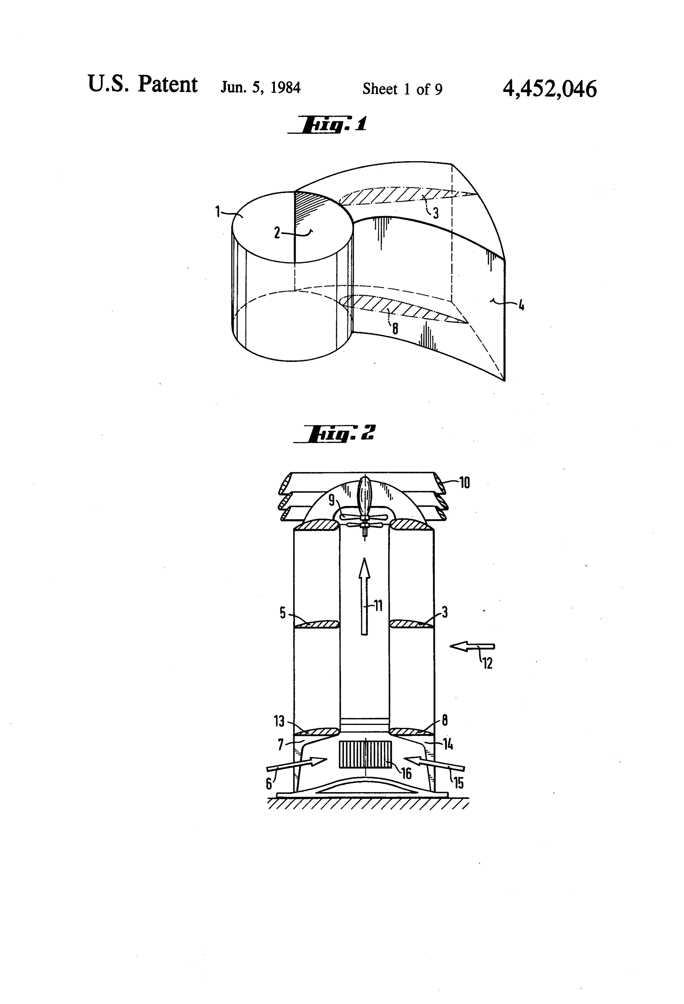
known phenomena such as cyclones, tornados, ty phoons, whirlwinds, etc. to be reproduced by analogy 20 FIG. 21 isshows
FIG.
a vortex duct of a cyclonic tower;
diagrammatic view of a cyclonic or anti and allows the energy produced therein as well as desa linated water to be obtained. For the description of the cyclonic tower;
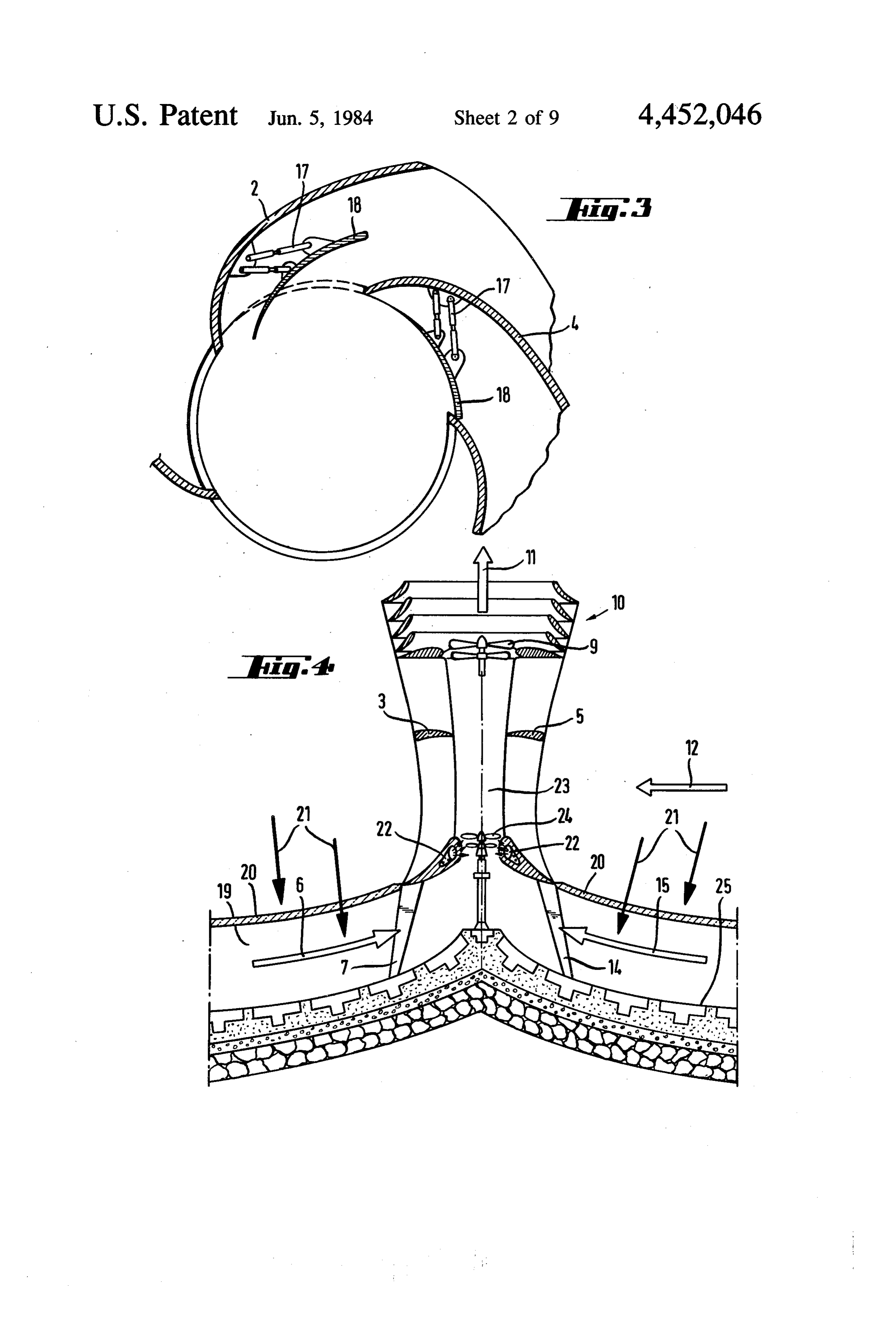
system, we will make use of a concrete example of the FIG. 3 is a cross-section through a tower of convec design to which there correspond the enclosed figures tors showing vertical screens and blocking devices; presented as embodiments, which are not intended to be 25 FIG. 4 is a fragmentary view of an energy converter limiting since the specific data in each case are in accor unit;
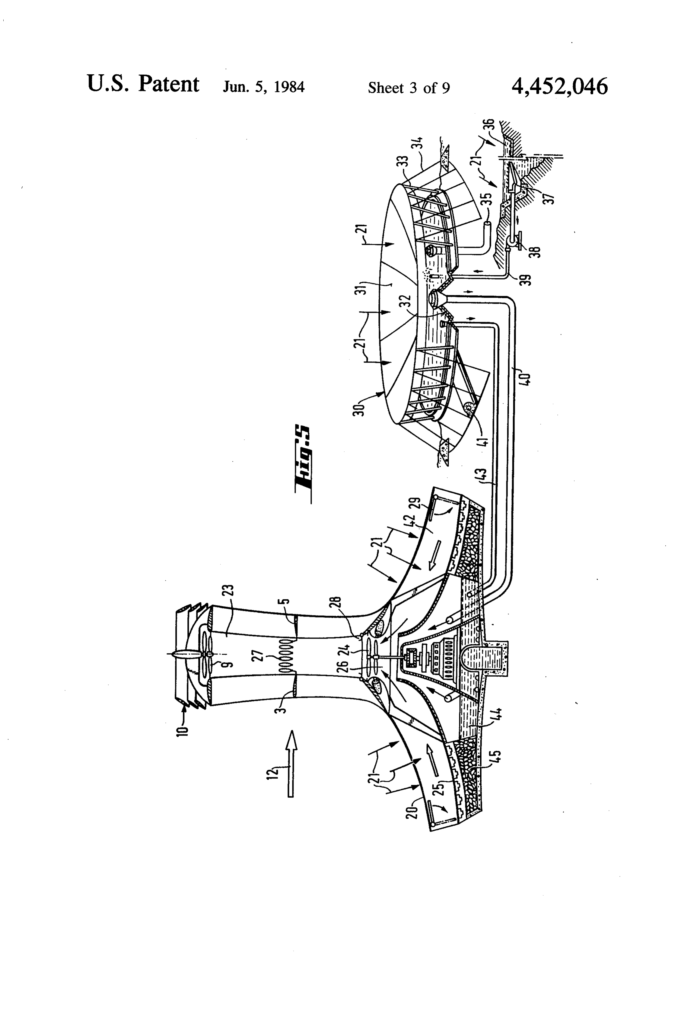
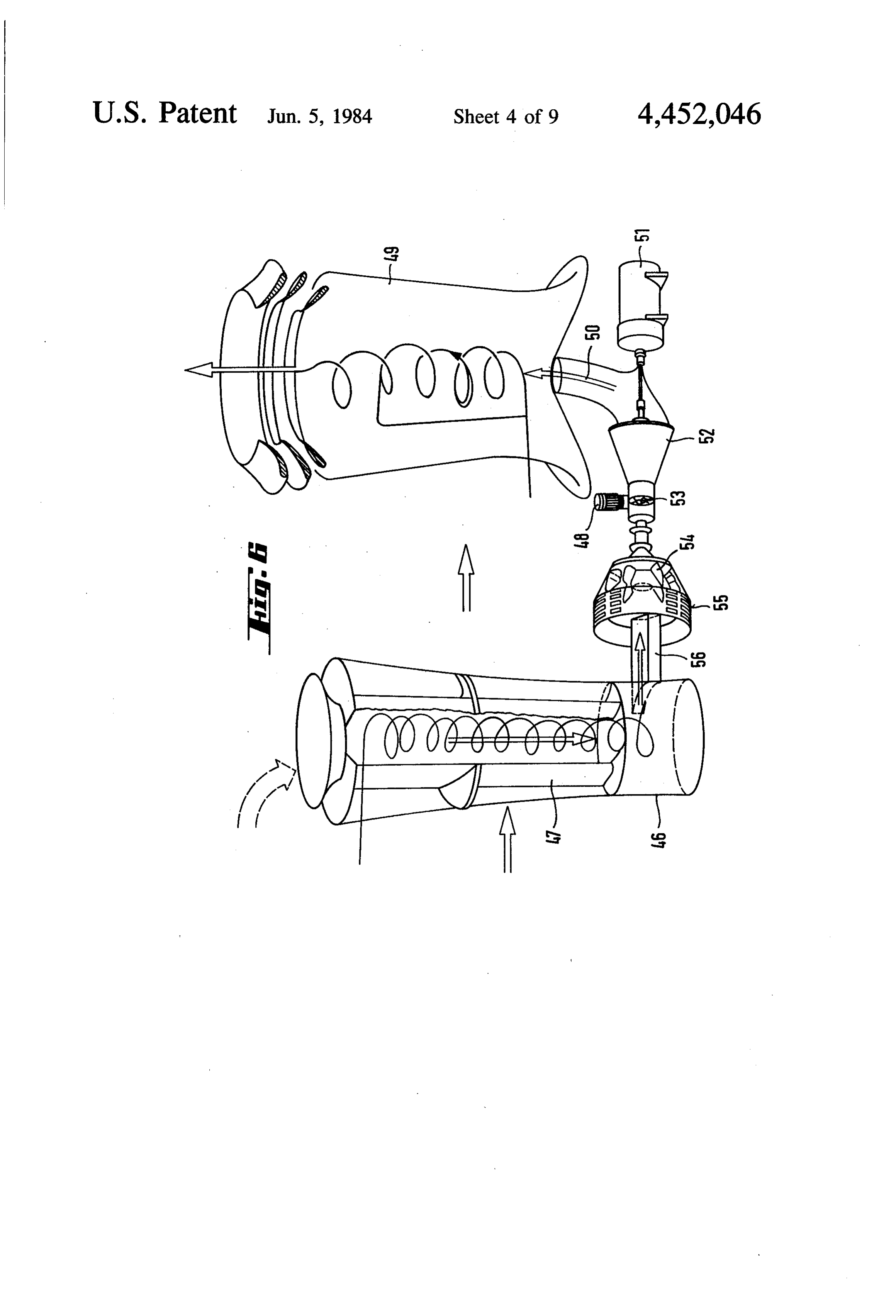
dance with the requirements of the design, without the FIG. 5 illustrates another form of cyclonic tower; modifications in detail affecting the essence protected in FIG. 6 illustrates a combined cyclonic-anti-cyclonic a general manner by the present registration. synergetic system;
SUMMARY OF THE INVENTION
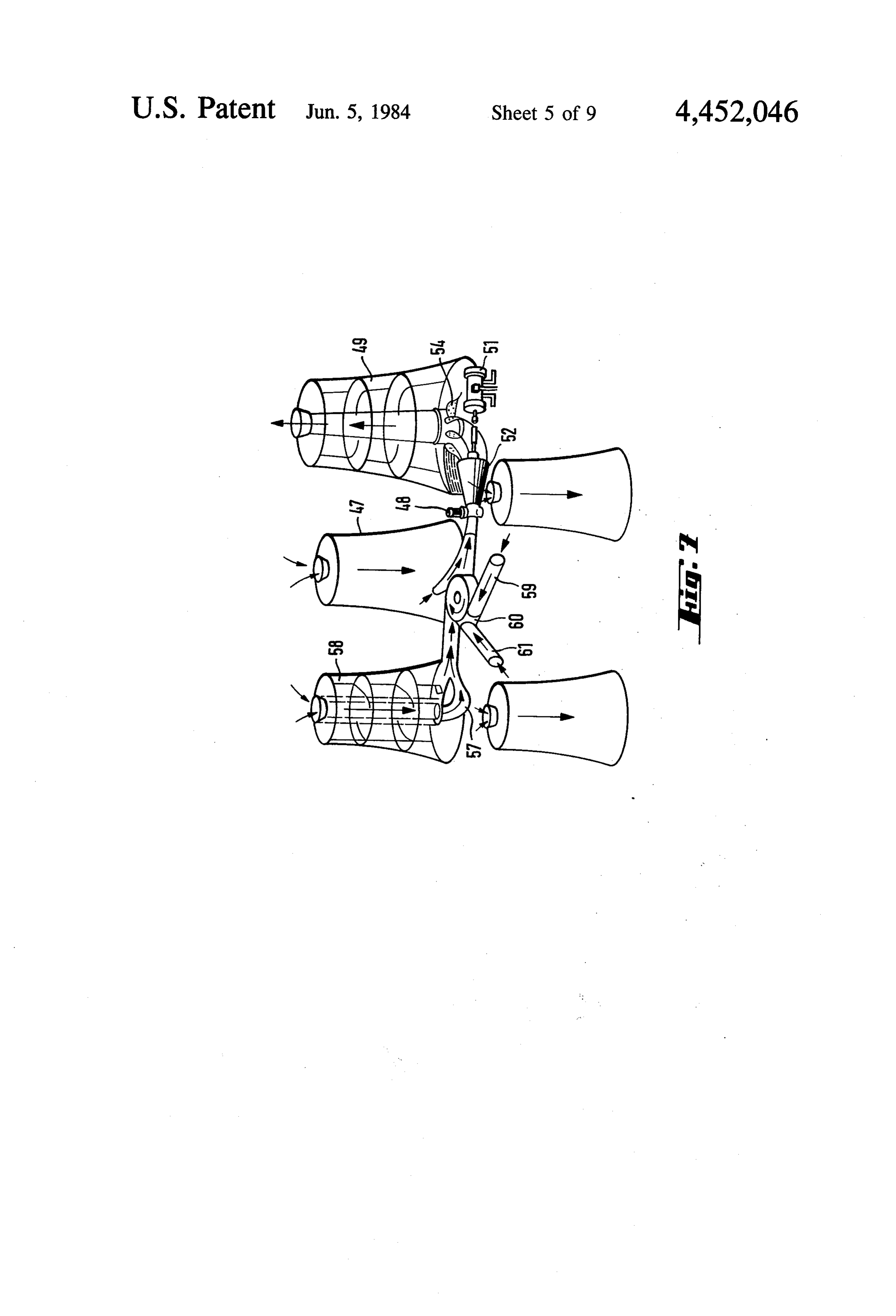
FIG. 7 is a diagrammatic representation of the mode of connection of units as shown in FIG. 4;
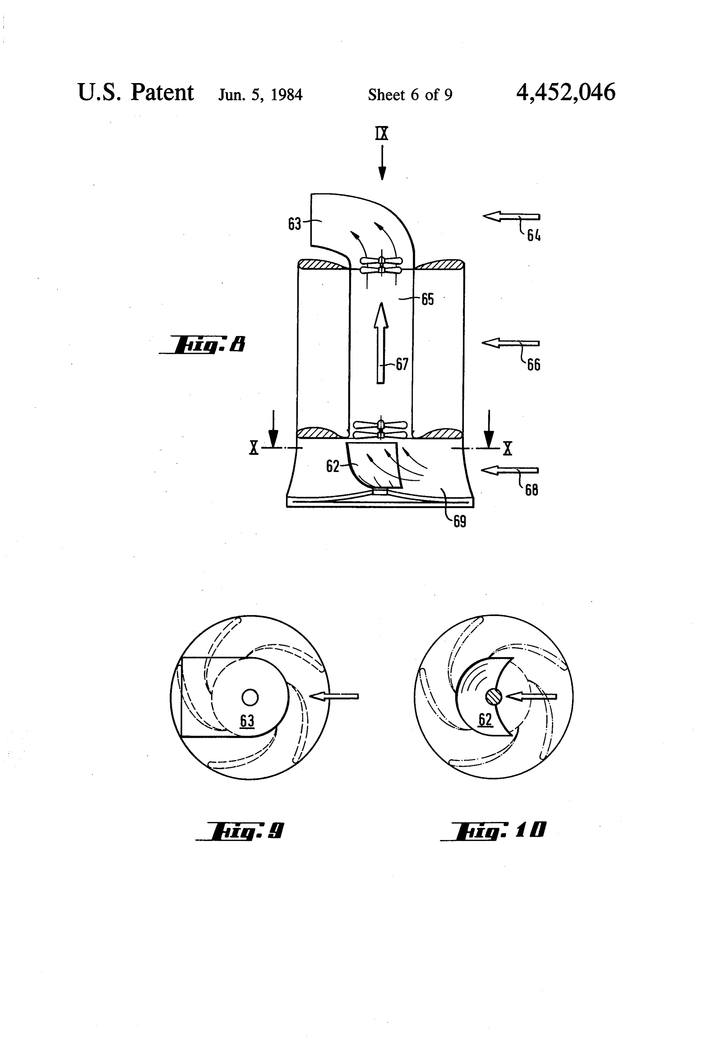
The system described differs from the prior art in that FIG. 8 is a diagram of an arrangement of deflector it allows use to be made of 83% of the energy in con diffusers;
trast to the considerably smaller percentages obtained at FIG. 9 is a plan view of the arrangement shown in present with wind systems, due to the fact that the 35 FIG. 8:
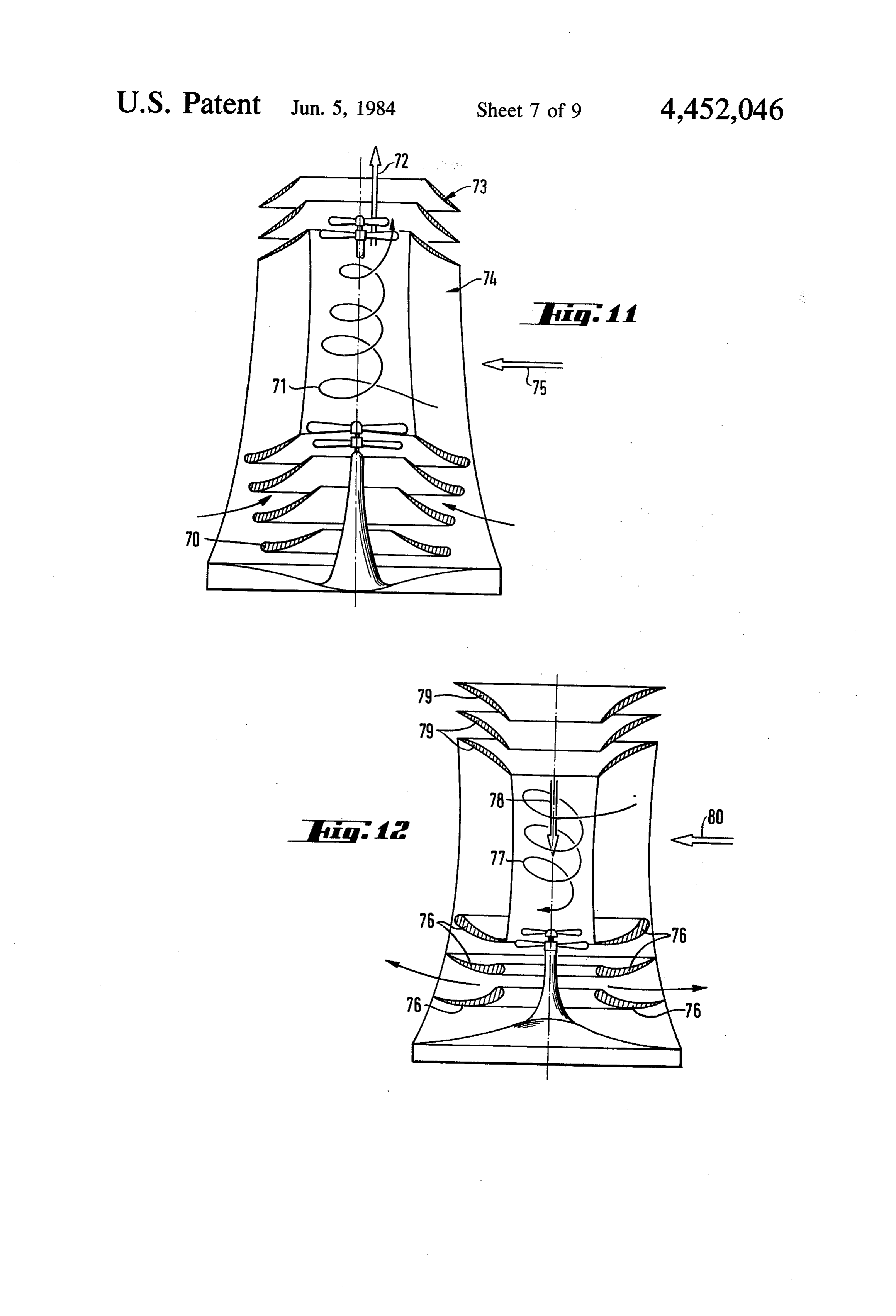
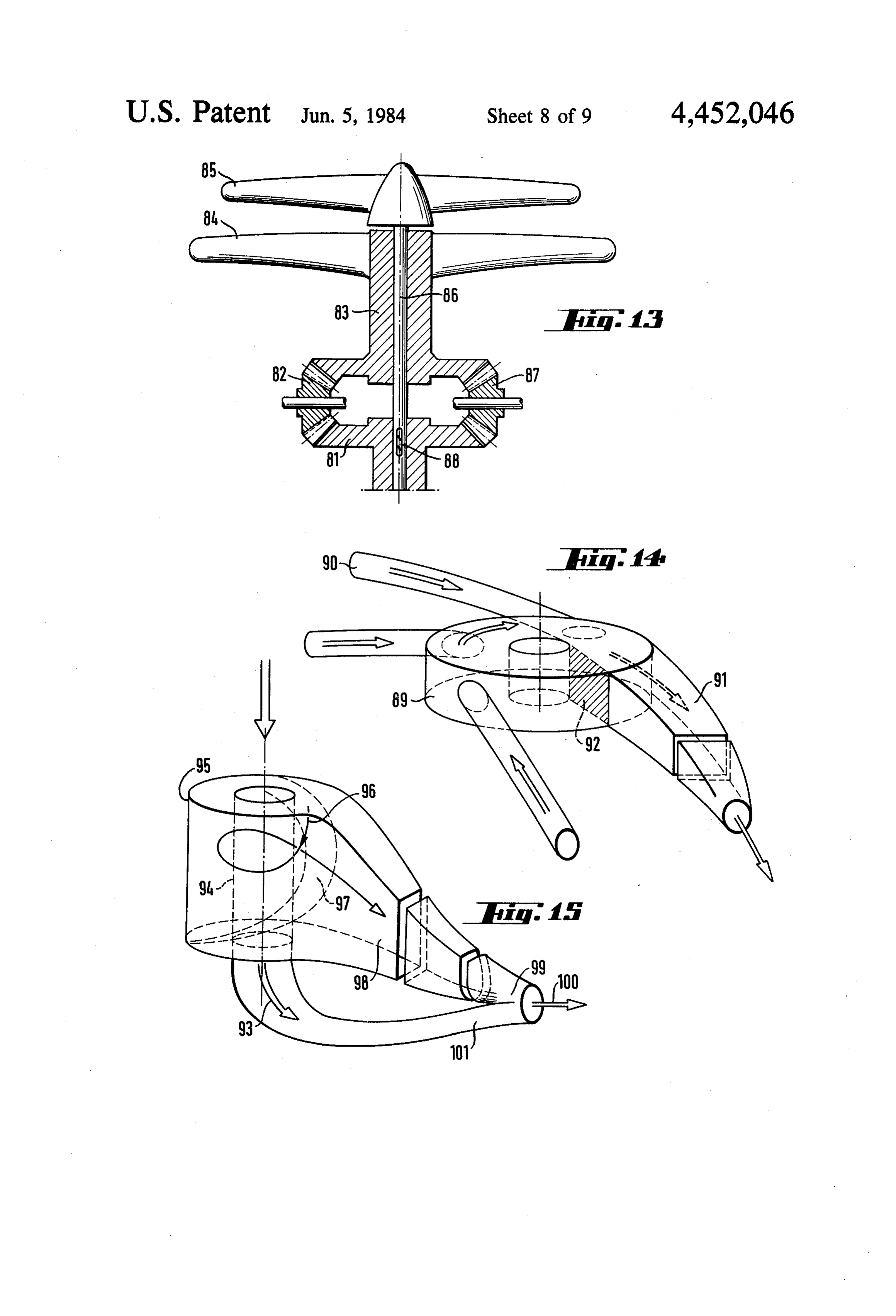
entering flow is subjected to convective acceleration by FIG. 10 is a section on line X-X of FIG. 8: natural causes, consequently producing the three basic FIG. 1 shows a cyclonic conversion device with flows of a natural cyclone which are: the convective fixed concentric screens;
flow accelerated by the law of continuity, the non-rotat FIG. 2 shows an anti-cyclonic conversion device; ing flow, and the rotating flow, which permits vortical 40 FIG. 13 shows a force rotation reversal device; nuclei of limited size to reach very high degrees of FIG. 14 shows a flow collector; energy concentration without design limits in the size of FIG. 15 shows a decyclonizing device; and the structures used.
One of the fundamental elements for the artificial FIGS. 16, 17 and 18 show alternative forms of flow production of cyclones or anti-cyclones is constituted 45 regulation devices.
by the convectors composed of two vertical membranes DETAILED DESCRIPTION OF THE or screens which are almost tangential to a central cy INVENTION lindrical duct whose generatrices follow a curved pro file in such a way that their presence, together with the convectors with theirare
Cyclonic towers composed fundamentally of central duct, causes in the flow an acceleration defined 50 FIG. 1 which shows vertical duct vortical as in the drawing in membranes or screens 4 by the laws of aerodynamics, compelling the natural wind to increase its velocity, accelerating at three con and 2 joined together by stiffeners constituted by hori secutive points which are: the curved screen, the actual zontal plates with streamlined sections 3 and 8. The vertical screens 4 and 2 of which there are two per convector, and the vortical duct. These convectors are at any level, without communicating with the flow at 55 convector are generated over a curve such as a circle, the floor or foundation level of the system, and are ellipse, hyperbola, parabola, logarithmic or hyperbolic intended to convey, deflect and accelerate convectively spiral or any other type, to a suitable height, and be tween each two consecutive screens 2 and 4 there is a substantially horizontal transverse flow.
The system permits the reproduction in suitable formed a convector which concentrates the flow of structures of confined artificial cyclones which, in the 60 energy flowing to the vortical duct 1 divided by all the same manner as natural cyclones, make use of the solar convectors if there are more than one. A cyclonic or energy as well as the kinetic and thermal energy in the anti-cyclonic tower is constituted by one or more con atmosphere. vectors like the one just described which are formed Similarly, this system permits different thermal ex between two stiffeners 3 and 8 and two consecutive ploitation of sea water to be integrated in a technologi 65 screens 2 and 4 forming various levels, the tower being cal device encompassing wind, radiant solar, and ther cyclonic if the fluid turns in an anti-clockwise direction mal sea water energy, creating a transformation which and anti-cyclonic if it turns in a clockwise direction, in uses not only the kinetic energy of the wind but also the the northern hemisphere.
Page 12
FIG. 2 shows a diagrammatic cyclonic or anti vector and the other by transposition of kinetic energy cyclonic tower. Four stiffeners 3, 5, 8 and 13 and the in the main flow.
tower-supporting piles 14 and 7 can be seen therein. In The heat accumulator and the thermally absorbent this Figure the arrow 12 indicates the direction of the black bottom 25 constitute a regulating element which wind entering the tower and the arrow 11 the direction accumulates the heat during the day, giving off surplus of the flow making this tower a cyclonic tower as the at night and thus balancing the thermal wind. direction is from bottom to top. The flow also enters in The thermal energy plus the transposed kinetic en the directions indicated by the arrows 15 and 6, which ergy give to the energy converters 24 and 9 in FIG. 4 flow actuates the relevant converter device which, in their combined energy under the regularizing interac FIG. 2, is a turbine 16 at the bottom, an assembly of 10 tive influence of the paravortical flows created recipro propellers or blades 9 being situated in the upper por cally.
tion, of which the rotors are contra-rotating and are at To regularize the use of the installation in calm or the top of the tower inside the diffusers 10. The deflec cloudy climatic conditions, the tower with conversion tors would be situated in the lower portion of FIG. 2. 15 of radiant solar energy is provided with an artificial Devices for transforming the kinetic energy of the heating aid based on burners 22 of gases of liquid fuels flow into electrical or mechanical energy, such as arranged in such a way that the entry of the hot gases of pumps, generators, compressors, dynamos, alternators, combustion will take place tangentially and horizon etc. are situated without distinction at either of the ends tally at the base of the vortical duct 23 and with such an or at both ends, both at the base and at the top of a 20 arrangement that the exhaust gases create an artificial tower of convectors. vortex with suction at the secondary suction base 19 FIG, 3 shows a cross-section through a tower of after having actuated the blade-type energy converter convectors, showing the section of the vertical mem 24.
branes or screens 4 and 2 as well as the blocking devices In a unit like the one just described, it is possible to 18, for blocking the intake of the flow into the vortical 25 use radiant solar energy and optionally thermal energy duct resting on the damping arms 17 turning about the originating from combustion together with or distinctly support and opening when they are located at the con from wind energy.
A unit like the one described with reference to FIG.
vector which should permit the passage of fluid by attracting it in the direction of the wind, providing that 4 is provided with a base in the form of a tank 44 having the streamlined profile of the blocking device 18 posi a low level of water (FIG. 5) which receives hot water tions it in such a way that it has the minimum resistance and saturated air from some pre-evaporators known as thereto and, nevertheless, shuts itself when the fluid hydric hothouses 30 with a black thermally absorbent attempts to circulate inside the convector towards the bottom 32 which is covered by a transparent surface 31 exterior from the vortex already created. The blocking constituting the membrane sheet covering which forms devices 18 turn when the air enters a convector in such 35 hothouses 30 over the surface or sheet of water supplied a direction that it pushes the blocking device 18 from from a large natural or artificial sheet of water 36 pre the outside inwards causing it to be located in the posi heated by the sun's rays 21 and trapped by the surface tion having least resistance to the intake of air, whereas sea water collector 37 pumped by the pump 38 which reaches the hydric hothouse 30 through the pipes 39 it remains closed when the air travels from the inside outwards, keeping this given convector blocked. The 40 located above the thermally absorbent black bottom 32 convectors have one or more recovery damping de and is heated even more by the sun's rays 21 striking the vices 17 which are actuated in a suitable direction by membrane sheet covering 31. This air is sent through the actual flow. the pipe 40 connected to the saturated air inlet to the top If the blocking devices 18 lengthening the membranes of the tank 44. In the same way, the tank 44 is filled by 2 and 4 beyond their tangent to the flow until they form 45 means of the pipes 43 with hot water from the hydric part of the vortical duct are removed from the convec hothouse 30. The transparent covering 31 is supported by the pillars 33 and tightened by the tension rods 34.
tors described with reference to FIG. 3, convectors will be obtained which can be used for units in which the The ambient air enters the above-mentioned hothouse power will be up to 5 kilowatts and the output will be of via the duct 35, the duct 41 serving for the extraction of little importance with the considerable advantage that 50 salt. In the tank enclosure 44, due to the water received moving parts will be eliminated. by it through the pipe duct 43 and the saturated air If the cyclonic conversion tower described above is reaching the top from the hydrichothouse 30 through provided at its base with a face 20 (FIG. 4) permitting the pipe duct 40, it is possible to create the thermal the passage of solar radiation 21, said face 20 being conditions of a natural cyclone at the base of the cy made of for example glass, plastics, etc., preventing 55 clonic converter.
reflection to the ambient air retained under the face 20, Using these devices it is possible to integrate the kinetic energy of the wind, the radiant thermal solar in the scope of secondary suction by the cyclonic con energy, verter due to the known hothouse effect, the radiant the energy produced by combustion, in the base solar energy is in the form of unstable hot air. of the vortical duct, of gases or liquid fuels, the energy To increase the radiant heating effect of the solar 60 of the hot water at the surface of the sea due to satura cyclonic system, the system will comprise, at its base, a tion by hot air and the energy obtained by insulation of thermally absorbent black bottom 25 made of a material hydric hothouses 30.
As they can all be integrated easily, the maximum capable of accumulating heat.
The energy converter 24 which, in FIG. 4, is consti naturalwhether energy available can be extracted at any mo tuted by two propellers mounted on contra-rotating 65 ment it is wind, solar, or thermal, from the sea. axles, receives the flow of thermal and kinetic energy. In the absence thereof, energy can be supplied by liquid There are therefore two energy vectors in the displace and/or gaseous fuels, thus making the system indepen ment of the flow inside the vortical duct: one thermal dent from the prevailing climatic conditions.
Page 13
In the tower illustrated in FIG. 5, the kinetic energy an anti-cyclonic tower 47, the flow will be sent through of the wind creates a depressed column drawing in the a duct 56 traversing an energy converter 52 which unsteady hot air generated by the face 20, the thermally actuates an electric generator, for example 51, continu absorbent black surface 25 and the accumulator 45. The ing to travel in the direction of the arrow 50 where it is rising column of air sucks saturated hot air from the 5 sucked through the cyclonic tower 49. The system is pipes through duct 26 while the hot water enters completed and improved by a combustion module 55 through the tubing pipe 43. provided with burners 54 which supply energy when The most suitable mixtures of saturated air and dry air the climatic conditions do not assist operation of the 42 can be made by means of the blocking devices 29 system.
acting as throttling deflectors for the secondary suction 10 Finally, a plate diaphragm 53 which is operated by a ducts. hydro-pneumatic servo-mechanism 48 opens or closes This cyclonic tower which can be completely regu the suction duct 56, thus controlling operation and in lated lifts a column of saturated air by means of the cluding the power of the system.
depression created by the kinetic energy. The condensa When the axes of the cyclonic and anti-cyclonic tow tion of this air at a given height of the cyclonic conver- 15 ers 49 and 47 are spaced apart as viewed in the direction sion tower can produce at will condensed and desali 50 of the prevailing flow, the space being known as the nated water which is gathered in the thermal condens "disturbance length', the system is such that the second ers 27 and is collected in the receivers 28 by means of tower 49, aligned with the main uniform flow, receives suitable channels or pipes. the flow already disturbed in velocity by the first tower The heat of condensation imparted to the column of 20 47, the energy rising air reinforces the rising flow of the vortical flow, tower 49 being per unit area of collection in the second increased significantly due to the higher increasing the depression column and the paravortical velocity of the flow disturbed by the first tower 47 in flows. The rising thermal column generated in this way the direction 50 of the flow. can therefore replace the kinetic energy of the wind up The cyclonic system combined with the anti-cyclonic to the level of a confined and established cyclone. 25 system with a disturbed rate in the flow demands the The condensation of the saturation water from the sucked air provides the system with an external thermal 49) bringing together of the conversion units (towers 47 and energy source which keeps the confined cyclone in the separationwhile the conventional propeller system demands motion even in the absence of paravortical winds, that is of the propeller supporting towers. to say the fundamental kinetic flow used for the priming 30 In this case, it is found that, unlike what happens with and unleashing of the cyclone. Sufficiently large hydric the conventional propeller-type converters when one hothouses 30 provide a natural and economical system flow is caused to act upon another, the combination of for trapping solar energy and transforming it into the the two towers 47 and 49 collects more energy than kinetic energy of rising air which can be used and trans each tower would collect individually. A dual combination like the one just described is formed in a converter with turbines and propellers 9 to 35 suitable produce electrical power. for single-direction flows like those existing in The air 42 as well as the air at the top of tank 44 mountain gorges for catabatic (abating) flows or in collects and rises through the vortical duct 23 actuating coastal zones for thermal winds. These combined cyclonic-anti-cyclonic systems are the propellers 24 as it passes through them. This FIG. 5 also shows that the sun's rays 21 heat the face 20, and 40 obviously improved by removing some screens located on the leeward or windward side between the towers 47 stiffeners 3 and 5 are streamlined, which form part of adjacent convectors traversed by the air from wind and 49 or by replacing them with guide screens. The direction 12. optimum disturbance length is a function of the prevail All the components described up until now with this ing mean velocity of the flow. The distance at which reference to FIG. 5 can be used together or separately. 45 phenomenon takes place with maximum intensity Of course, the arrangement shown in this FIG. 5 is will be called "induced disturbance length'. neither restricting nor limiting, and the face 20, the The compound or combined arrangement of the sym hydric hothouse 30 and the burners 22 (FIG. 4) can be metrically reciprocal cyclonic-anti-cyclonic systems arranged in any manner providing that the physical permits high density energy collection and conversion effect of regulation and integration of the flows are 50 systems for wind energy to be concentrated over rela combined in an ascending driving vector of the air tively small areas. This phenomenon is identical to and column propelling the elements for converting the en has the same causes as the disturbances in the wind ergy received into electrical energy for turbines, pro between high-rise buildings.
pellers etc., which are coupled to the generators or FIG. 7 shows diagrammatically the connection be other means of exploitation such as pumps, compressors 55 tween the various units such as those described above or accumulators. which are spaced apart at distances known as induced In a manner similar to that in which cyclonic towers disturbance length which, as already stated, is the dis are produced, an anti-cyclonic tower is obtained if the tance producing the optimum output, the units being rotational direction of the entering air is reversed, with situated in such a way that their distribution is similar to the characteristic inherent in it and in our hemisphere 60 the pattern of winds and velocities prevailing at the that the vortex will travel from top to bottom instead of location. This multiple combination results in an in from bottom to top as things happen in the opposite duced disturbed flow which we will call for short direction in the other hemisphere. "poly-fluper" (from poly-flujo-perturbado), which pro FIG. 6 shows a combined cyclonic-anti-cyclonic duces a high output in the concentration of wind energy system which is synergetic. The method of making use 65 since this arrangement is the most suitable for the con of the combined effects of a cyclonic tower and an struction of large power stations based on wind energy, anti-cyclonic tower will be described with reference to producing levels of installed power similar to those of this FIG. 6. In fact, by connecting a decyclonizer 46 to large thermal, hydraulic or nuclear power stations.
Page 14
FIG. 7 shows an example of a multiple combination clonic system converting a horizontal wind 75 into a for omni-directional wind comprising a cyclonic unit Vortex. 7 with propulsion in direction 72 and in the and several anti-cyclonic units distributed in a horizon northern hemisphere, a top diffuser 73 would collect the tal plane over the pattern of prevailing winds and direc flow at the top, preventing the occurrence of horizontal tions, illustrating how various anti-cyclonic units 58, shearing forces when the vortical flow leaves the tower each with their decyclonizer 57. In the anti-cyclonic and thus helping the soft leeward shift of the vortex and unit 47 air is arriving via intake ducts 61 and 59 which its diffusion in the uniform main flow. converge in the collector 60, the energy originating The base deflector 70 acts similarly at the base, pre therefrom traversing the diaphragm regulated by the venting the formation of low pressures. In this case, the Servomechanism 48 and then arriving at the energy O significant difference can be convergence in the diffuser converter unit 52, actuating the electrical generator 51, or diffusers and divergence in the deflectors, as shown and passing through the duct with burners 54 operated in FIG. 12 which illustrates an anti-cyclonic system. by hydrogen or a different fuel situated around its pe In FIG. 12, the incident energy flow 80 rotating in a riphery, finally traversing the cyclonic module 49 in clockwise direction 77 causes a descending flow 78 which the flow therefrom is combined with the earlier 15 toward the energy converters. The head deflectors 79 flows producing the maximum energy. compel the flow to descend through a vortical duct In the following pages, we will describe in sufficient while the base diffusers 76 create a depression due to detail some of the components of the systems forming their convergence which helps the exit of the descend the subject of this specification: ing flow.
The devices blocking the vortical duct tend to close 20 The deflector diffuser is consequently formed by one, when the air attempts to issue outwards from the vorti two or more discs of variable size with a concentric cal duct and to open when the air tends to pass towards orifice in the centre thereof with a streamlined cross the vortical duct. section which converges and/or diverges from the in Although deflectors and diffusers have opposing side out or from the outside in, depending on whether it functions, in the cyclonic-anti-cyclonic energy system, 25 acts as a diffuser or deflector. due to the axial symmetry of the flows in each, the In the northern hemisphere, with an anti-cyclonic designs can be identical with a deflector for channeling system according to FIG. 12, the deflectors 79 diverge and concentrating the flow in the case of an anti-cylonic towards the centre whereas the diffusers 76 converge flow whereas the opposing function of distributing and towards the axis.
diffusing the issuing flow into a uniform flow can be 30 Deflector diffusers of the venturi or cylindrical or fulfilled in a cyclonic system. hemispherical type with doubly swinging plates are FIG. 8 shows a diagram of such an arrangement with obviously also utilized frequently and are widely used in several deflector diffusers with tubular bends, with the these systems as well as deflector diffusers combined aim of increasing and improving the energy collection with all those mentioned up until now. and conversion capacity of the installation. 35 In order to transform and utilize the energy in the Although the structural geometric relationships are transposed flow (or secondary vortical ascending or different, in order to produce an omni-directional orien descending, linear or rotating flow), there are used tation relative to the wind which is suitable in both various devices such a double or single concentric, cases, the principle is the same. contra-rotating turbines as well as conventional propel FIG. 9 shows a plan view of FIG. 8, and FIG. 10 is lers or propellers modified according to the geometry a section along line X-X in FIG. 8. and the flow of the path of the lines of the energy cur The flow from direction 68 which enters at inlet 69 rent, or double, contra-rotating propellers arranged in (FIG. 8) covers the secondary flow sucked in by the the secondary flow to make use of the sucked or pro vortical duct 65 in a cyclonic system from the wind pelled flow or the ascending thermal flow, if any, for travelling in direction 66. The external flow 64 entering 45 the cyclonic or anti-cyclonic systems described herein above the diffuser 63 also creates a leeward depression as well as the main paravortical or substantially hori which assists the suction and diffusion of the issuing Zontal flow.
flow. This produces the geometric addition of the gen Other possible devices include turbines with multiple erated energy vectors 67. blades and a fixed or rotating deflector for air and/or This FIG. 8 shows clearly that the diffuser 63 also 50 hot gases in simple cyclonic installations, combined acts as a deflector 62. anti-cyclonic installations or multiple poly-fluper instal When changing hemisphere with the same system, lations.
the deflectors 62 act as diffusers 63 and the diffusers 63 In all cases, the use of simple propellers or turbines act as deflectors 62, and they are all utilized for the first for the conversion of the transposed or induced energy time in these cyclonic and anti-cyclonic systems and 55 flow produces a low collection capacity of the order of they can be either capable of orientation or static and 59% maximum. In order to improve this capacity, dou concentric like those shown in FIG. 11 which shows a ble contra-rotating energy converters are connected to cyclonic conversion device with fixed screens 74 which the cyclonic and anti-cyclonic systems to produce indi form the corresponding convectors provided with ces of collection of approximately 83%.
blocking devices 18 (FIG. 3) which oscillate in the 60 For this purpose, it is necessary to reverse the direc direction of the main flow. In the case which we are tion of rotation of the resultant force by combining it describing with reference to FIG. 11, the deflectors and with the force of the other concentric device, as shown diffusers can be constructed in the form of a disc with in FIG. 13. In this FIG. 13, the propeller 85, which can an orifice in the centre and with a streamlined cross-sec be substituted by a rotor or turbine, rotates in a given tion, parallel to each other converging and/or diverg 65 direction entraining the axle 86, for example, in a clock ing from the inside out or from the outside in, depend wise direction while the propeller 84 which entrains the ing on whether they have the function of diffusion or axle 83 rotates in the opposite direction. Owing to the deflection (FIG. 12). In FIG. 11, in the case of a cy conical gears 87 and 82, this rotational direction is re
Page 15
versed in such a way that the body 81 rotates in the the same way as solar energy which we will describe same direction as the axle 86, making the movement of the two axles 83 and 86 integral by means of the pin 88. separately below owing to its importance. The flow collector (FIG. 14) has the object of chan the following amanner:
First of all, hydro-wind system can be produced in nelling and orientating the flows from various anti- 5 The electrical energy from cyclonic and/or anti cyclonic systems or sucked by the cyclonic system cyclonic power stations can be applied to the operation towards the common energy converter, and for this of reciprocating pumps or turbines or reciprocating purpose it is constituted essentially by a body 89 whose generators which pump water from the opposing dams walls are formed by two concentric or non-concentric cylinders which are closed at the top and the bottom. 10 inforhydraulic installations so that the water consumption The ducts 90 transporting the flow from the anti tionthe production of electricity is reduced to evapora or filtration losses.
cyclonic systems enter this body 89. To produce the cylindrical configuration of the flow, it circulates cir This arrangement opens up great possibilities not cumferentially, permitting the subsequent addition of expected hitherto. Firstly, it permits the exploitation of flows from other systems, up to a given point at which 15 hydraulic basins which, owing to their steep gradient, a tangential screen 92 is connected to a common outlet did not allow large tailings dams and a damming capac duct 9. ity sufficient to justify the installation of hydro-electric The flow from duct 91 can be connected to an energy power stations. Secondly, in locations where they al converter and to the suction of a cyclonic tower. ready exist, it liberates large volumes of water for indus When it is necessary to transform the non-rotating 20 trial, agricultural or domestic use which, up until now, and rotating flow of the vortex into a linear flow again had to be available in reservoirs in order to be used for so that it can be integrated into the common flow, for energy.
example, by decyclonizing and devortizing the flow, Since the cyclonic anti-cylonic system relies on inex there are devices called decyclonizers or devortizers, as haustible and recoverable wind energy, radiant solar illustrated in FIG. 15, which shows that the device 25 energy and marine thermal energy, it makes it possible essentially consists of two concentric cylinders 95 and to construct large power stations having a potential 94 in whose interior there is arranged a conoidal de level per unit of the order of thermal, hydraulic or flecting surface 97 which compels the flow to enter the nuclear energy, thus altering the accepted premises on curvilinear duct 98. The rotating flow 96 is composed of the availability of water and energy. the asymmetrical sheet legs 99 with the linearized flow 30 Cyclonic hydrogen system: by applying the energy of the vortex 93 descending in the duct 101. This linear obtained in cyclonic anti-cyclonic units, with or with ized flow 100 can be integrated in the collector with out assistance, to electrolytic modules supplied with sea flows from other origins or towers. water or unhygienic water, it is possible to obtain hy By throttling the flow 100 at the beginning or end of drogen at low cost and this makes it possible to obtain the vortical column, the fluid volume in the column 35 methanol or liquid fuels or, in combination with carbon, and, consequently, the energy therein changes per unit hydrocarbons, by means of the relevant technology. time.
One hydrogen wind unit can produce energy and
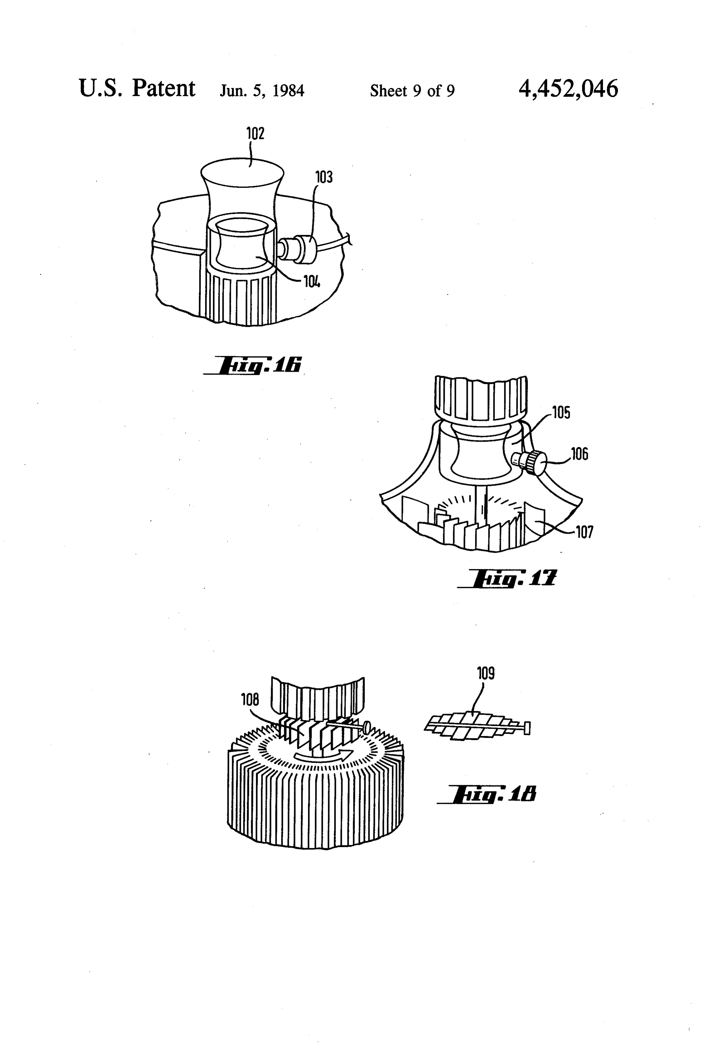
Regulators such as the one shown in FIG. 16 effect other valuable products or, in turn, hydrogen, oxygen, this regulation at the head or, like the one shown in all types of salts, and desalinated water. FIG. 7, at the base. Both devices regulate by means of 40 Just as the hydro-wind system is justifiable in moun an elastic cylindrical diaphragm 104 or 105 which is tainous countries, the hydrogen-wind system is particu situated at the end or at the beginning of the vortical larly suitable column, respectively. With the regulator in FIG. 16, the internal lakes for countries with coastal zones or with or landlocked seas.
flow reaches the nozzle 02 after traversing the elastic diaphragm 104, controlled by the servo-compressor and 45 is In view of the characteristics of the invention which claimed in a general manner and with reference to
The regulating devices are formed by a strong exter for obtaining energy by itmeans concrete embodiments, can be stated that the systems of flows similar to those nal cylinder and another flexible diaphragm-like con forming centric internal cylinder of which the diameter varies as tuted by the shapes and sizes consideredcantobebeconsti a natural cyclone or anti-cyclone most a function of the pressure and/or vacuum regulated in 50 convenient and by the most suitable materials for each the interior or cavity of the two cylindrical bodies via a servo-compressor and control valve 103 or servo concrete application, without variations such as those regulator 106. The diffuser or deflector devices 107 can which might occur in details of presentation and finish be seen at the base. affecting the essence claimed, since the systems con FIG. 18 shows a regulating device which is arranged 55 structed in accordance with such characteristics with without distinction at the beginning and/or at the end of any of these modifications will only be variations which the vortical column and which consists essentially of a are also included and protected by the present claims. variable number of flaps or shutters composed of slats I claim:
which open and close the vortical duct, regulating the 1. A wind-solar energy conversion system utilising flow through the vortical duct. This FIG. 18 clearly 60 cyclonic or anticyclonic fluid flow comprising: shows how the flaps 108 located in the flow path corre a cyclonic conversion tower having an axial fluid spond to the open position of the regulator whereas the flow vortex duct;
flaps 109 correspond to the closed position. at least one fluid flow convector arranged vertically The irregularity of wind energy means that it must be in the tower for concentrating lateral wind flow possible to accumulate the surplus energy in order to 65 into the tower into axial fluid flow along said vor satisfy the demand, as in the case of hydraulic energy. tex duct;
One of the basic applications of the claimed system is diffuser/deflector means, arranged at one end of the mass production for the accumulation of wind energy in tower, for augmenting fluid flow output;
Page 16
means, arranged at the top and bottom of the tower, and further includes stiffeners joining together the for converting kinetic fluid flow energy into an vertical screens and having a streamlined profile, other mode of energy; said system further comprising: a base means for supporting the tower and for admit fluid flow blocking devices mounted on damping ting solar energy to augment energy output; and 5 arms and turnable to and from positions in which a heating system, arranged in the tower, for augment they prevent fluid flow into or out of the vortex ing energy output when climatic conditions result duct.
in an insufficient supply of solar energy. 6. An energy conversion system utilising cyclonic or 2. The energy conversion systern according to claim anticyclonic fluid flow comprising:
1 wherein: 10 a cyclonic conversion tower having an axial fluid said base means incorporates a wind energy means for flow vortex duct;
generating the axial fluid flow for integration with at least one fluid flow convector arranged vertically the lateral wind flow, and in the tower for concentrating lateral wind flow said heating system utilises a fluid fuel to generate and into the tower into axial fluid flow along said vor augment axial fluid flow. 15 tex duct;
3. The energy conversion system according to claim diffuser/deflector means, arranged at one end of the 1 further comprising: tower, for augmenting fluid flow output; an elastic cylindrical diaphragm means, situated in means, arranged at the top and bottom of the tower, the tower, for throttling the fluid flow there for converting kinetic fluid flow energy into an through. 20 other mode of energy;
4. An energy conversion system utilising cyclonic or a base means for supporting the tower and for admit anticyclonic fluid flow comprising: ting Solar energy to augment energy output; and a cyclonic conversion tower having an axial fluid a heating system, arranged in the tower, for augment flow vortex duct; ing energy output when climatic conditions result at least one fluid flow convector arranged vertically 25 in an insufficient supply of solar energy; in the tower, for concentrating lateral wind flow wherein said at least one fluid flow convector is a into the tower into axial fluid flow along said vor hollow body formed by curvilinear and truncated tex duct; pyramidal surfaces;
diffuser/deflector means, arranged at one end of the said system further comprising: tower, for augmenting fluid flow output; 30 fluid flow blocking devices which are each mov means, arranged at the top and bottom of the tower, able about a vertical axis and are equipped with for converting kinetic fluid flow energy into an damping arms, and other mode of energy; servo-mechanism means for concentrating power a base means for supporting the tower and for admit due to fluid flow to the at least one fluid flow ting Solar energy to augment energy output; and 35 Convector.
a heating system, arranged in the tower, for augment 7. An energy conversion system utilising cyclonic or ing energy output when climatic conditions result anticyclonic fluid flow comprising:
in an insufficient supply of solar energy; a cyclonic conversion tower having an axial fluid wherein the at least one fluid flow convector includes flow vortex duct;
two vertical screens generated by profiles which 40 at least one fluid flow convector arranged vertically are tangential to the direction of axial fluid flow in the tower for concentrating lateral wind flow and further includes stiffeners joining together the into the tower into axial fluid flow along said vor vertical screens and having a streamlined profile, tex duct;
said screens merging into said vortex duct. diffuser/deflector means, arranged at one end of the 5. An energy conversion system utilising cyclonic or 45 tower, for augmenting fluid flow output; anticyclonic fluid flow comprising: means, arranged at the top and bottom of the tower, a cyclonic conversion tower having an axial fluid for converting kinetic fluid flow energy into an flow vortex duct; other mode of energy;
at least one fluid flow convector arranged vertically a base means for supporting the tower and for admit in the tower for concentrating lateral wind flow 50 ting solar energy to augment energy output; into the tower into axial fluid flow along said vor a fluid fuel heating system, arranged in the tower, for tex duct; augmenting energy output when climatic condi diffuser/deflector means, arranged at one end of the tions result in an insufficient supply of solar energy; tower, for augmenting fluid flow output; a wind energy means, incorporated into the base means, arranged at the top and bottom of the tower, 55 means, for generating the axial fluid flow for inte for converting kinetic fluid flow energy into an gration with the lateral wind flow; and other mode of energy; a low level water tank in the base means of the tower, a base means for supporting the tower and for admit an hydric hothouse being connected to the low level ting solar energy to augment energy output; and water tank and having a thermally absorbent black a heating system, arranged in the tower, for augment 60 bottom, ing energy output when climatic conditions result pipe means, interconnecting the hydric hothouse in an insufficient supply of solar energy; with the low level water tank, for supplying heated wherein the at least one fluid flow convector includes water from the hydric hothouse to the low level two vertical screens generated by profiles which water tank.
are tangential to the direction of axial fluid flow 65
Provenance
- Collection
- Cited prior art
- Original PDF
- patentimages.storage.googleapis.com →
- Filed
- 1981-07-08
- Pages
- 16
- Method
- pdftotext (the PDF's own text layer) + pdftoppm 300dpi page scans
- Source
- Google Patents bibliographic record
- Granted
- 1984-06-05
- Inventors
- Zapata M. Valentin
- Transcribed from
- patentimages.storage.googleapis.com →