patent · US4517483
Permanent magnet rotor with saturable flux bridges
14 May 1985
Page 1 — bibliographic record
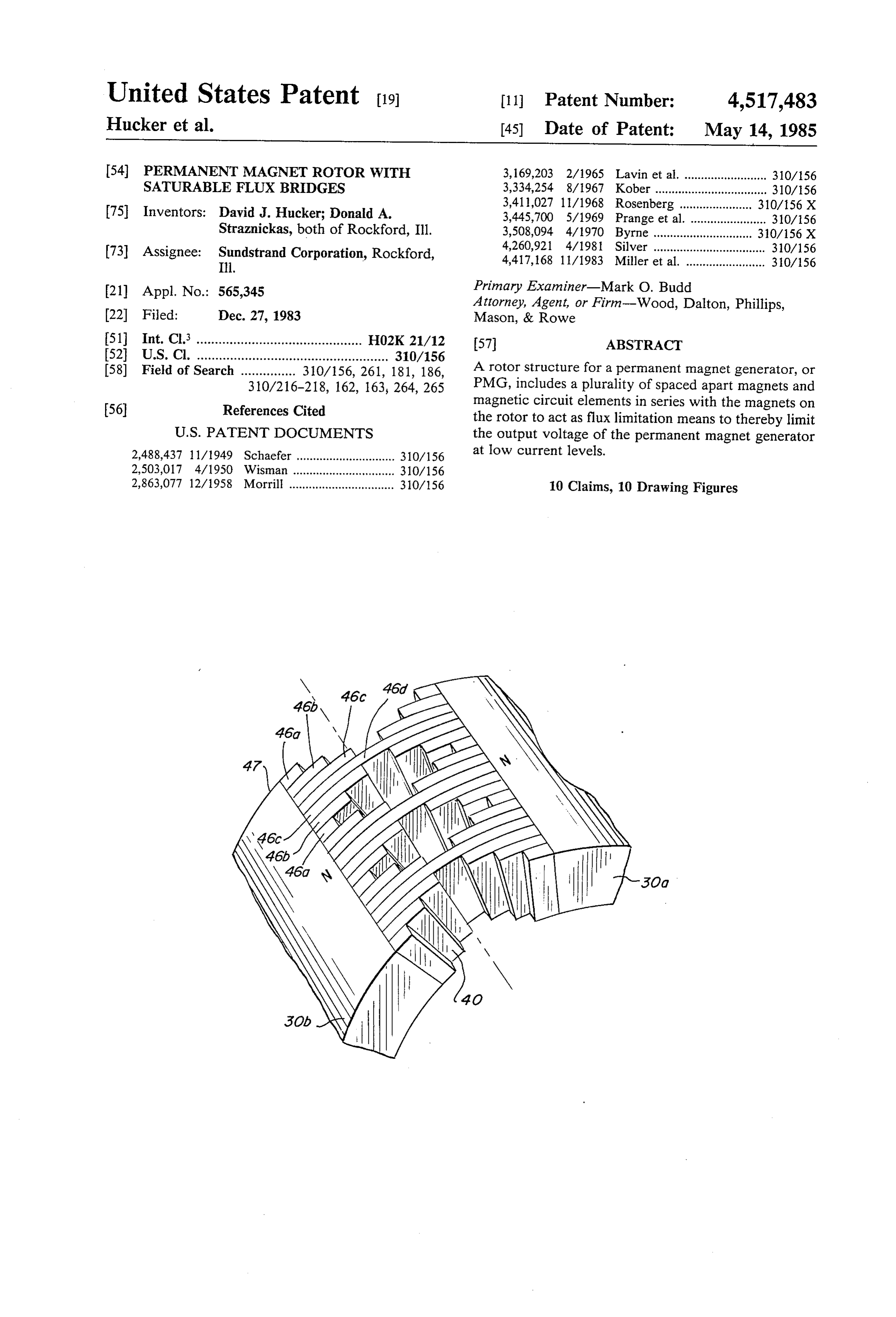
United States Patent (19) 11 Patent Number: 4,517,483 Hucker et al. 45) Date of Patent: May 14, 1985 54) PERMANENT MAGNET ROTOR WITH 3, 169,203 2/1965 Lavin et al. ......................... 310/156 SATURABLE FLUX BRIDGES 3,334,254 8/1967 Kober .................................. 310/156 3,411,027 11/1968 Rosenberg. ... 310/156 X 75 Inventors: David J. Hucker; Donald A. 3,445,700 5/1969 Prange et al. . ... 310/156 Straznickas, both of Rockford, Ill. 3,508,094 4/1970 Byrne .... ... 310/156 X (73) Assignee: Sundstrand Corporation, Rockford, 4,260,921 4/1981 Silver .................................. 310/156 Ill. 4,417, 168 11/1983 Miller et al. ........................ 310/156 21) Appl. No.: 565,345 Primary Examiner-Mark O. Budd Attorney, Agent, or Firm-Wood, Dalton, Phillips, 22 Fied: Dec. 27, 1983 Mason, & Rowe 51 Int. Cl. ............................................. H02K 21/12 57 ABSTRACT 52) - -- - - -- - - - - - - - - - - - - - - - - - - - - 310/156
58) Field of Search ............... 310/156, 261, 181, 186, A rotor structure for a permanent magnet generator, or 310/216-218, 162, 163, 264, 265 PMG, includes a plurality of spaced apart magnets and 56) References Cited magnetic circuit elements in series with the magnets on the rotor to act as flux limitation means to thereby limit
2,488,437 11/1949 Schaefer .............................. 310/156 at low current levels.
2,503,017 4/1950 Wisman. ... 310/156 2,863,077 12/1958 Morrill ................................ 310/156 10 Claims, 10 Drawing Figures
Page 2
Drawing sheet — no readable text.
Page 3
Drawing sheet — no readable text.
Page 4
Drawing sheet — no readable text.
Page 5
which voltage must be maintained at an approximately
PERMANENT MAGNET ROTOR WITH constant value. Accordingly, flux is limited below this SATURABLE FLUX BRIDGES maximum current level, and since voltage is propor
DESCRIPTION
tional to flux, the output voltage of the PMG is also limited.
1. Technical Field In a second embodiment of the invention, a series of The present invention relates generally to dynamo equally spaced radially polarized or magnetized mag electric machines and more particularly to a structure nets are disposed on a ferromagnetic yoke which is in for a permanent magnet machine or generator. turn mounted on a shaft. The yoke itself comprises flux 10 limiting means in that it is made sufficiently thin at least 2. Background Art
Permanent magnet generators, or PMG's, are inher in those portions between adjacent magnets to increase ently more efficient than wound rotor machines due to flux density to the saturation point for the yoke mate the fact that the PMG has only one winding which rial. The result is that flux, and hence output voltage, experiences copper losses as opposed to wound rotor are limited at desired levels.
machines which have multiple windings experiencing 15 The ferromagnetic material is selected to exhibit an such losses. abrupt change in permeability at the maximum design The recent development of high energy permanent load so that flux, and hence output voltage, is controlled magnet materials has aided in the design of permanent to no more than a particular value at current levels magnet generators, particularly those which are to be below design rating.
used in environments requiring low weight and high 20 While in the above embodiments, flux limiting is performance. However, the inherent nature of these accomplished by suitable dimensioning of ferromag high energy materials is that a large voltage drop occurs netic material in a magnetic circuit, it should be under as load is applied. For example, if the PMG is run at a stood that such flux limiting can be accomplished with constant speed and is proportioned to operate near the out maximum energy product of the magnets at maximum 25 iron dimensional change by utilizing materials such as or iron-nickel alloys which saturate at a particular power, the output voltage at no load (i.e. the open cir flux level.
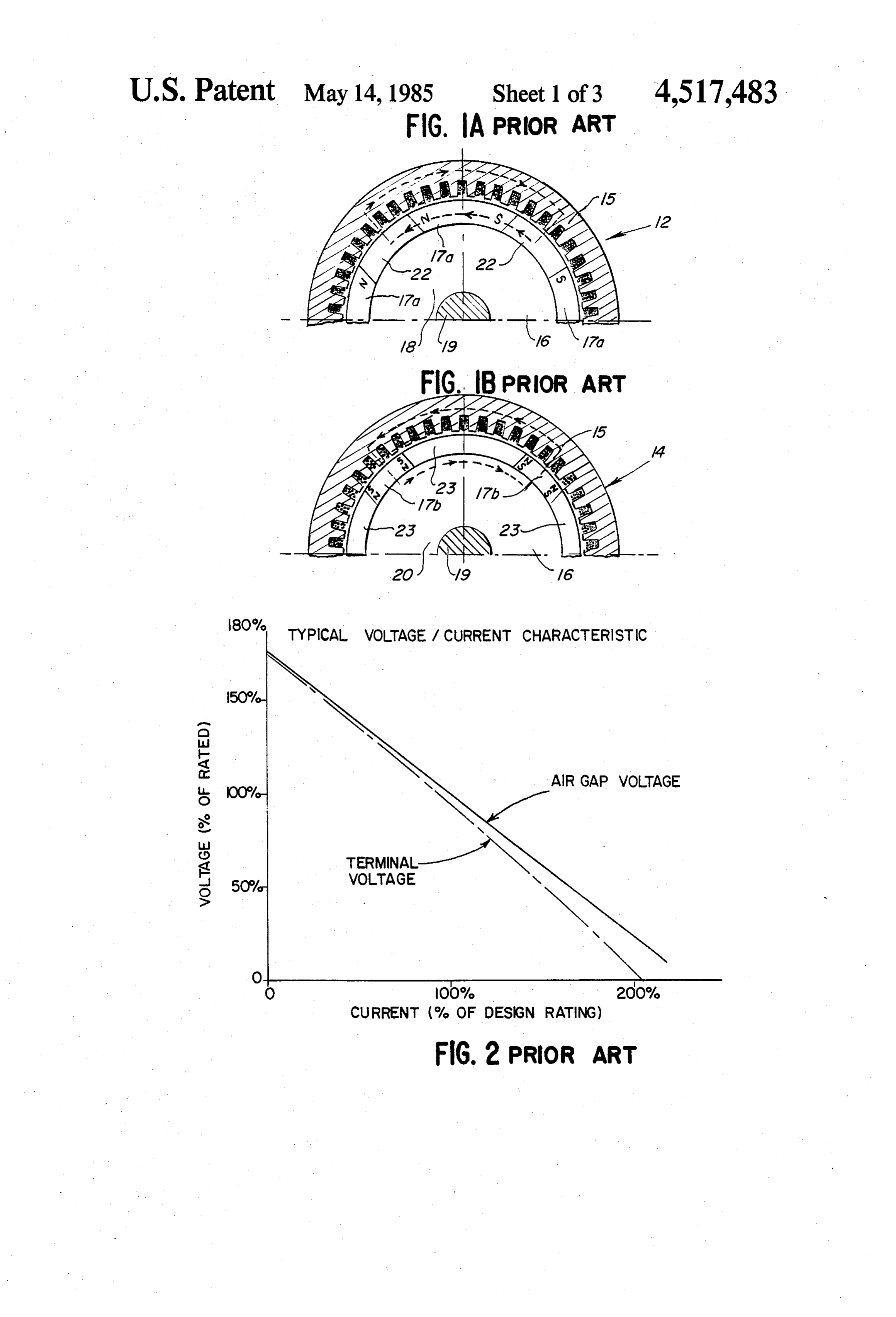
cuit voltage) may be approximately 70% of rated volt age. BRIEF DESCRIPTION OF THE DRAWINGS Hence, PMG's have typically been utilized only as an FIGS. 1A and 1B are fragmentary schematic views of auxiliary power source, for example, in a brushless al 30 prior art permanent magnet generators or PMG’s, FIG. ternator to supply field current to an exciter which in 1A disclosing a PMG utilizing tangentially magnetized turn develops main field current for a generator. Even magnets and FIG. 1B disclosing a PMG utilizing radi when used as an auxiliary power source, a voltage regu lator is required to ensure that the PMG output is main ally magnetized magnets;
tained at a substantially constant level. 35 FIG. 2 is a graph of the voltage/current characteris There have been various attempts to design improved tic for the permanent magnet generators shown in rotor assemblies for permanent magnet generators. For FIGS. 1A and 1B:
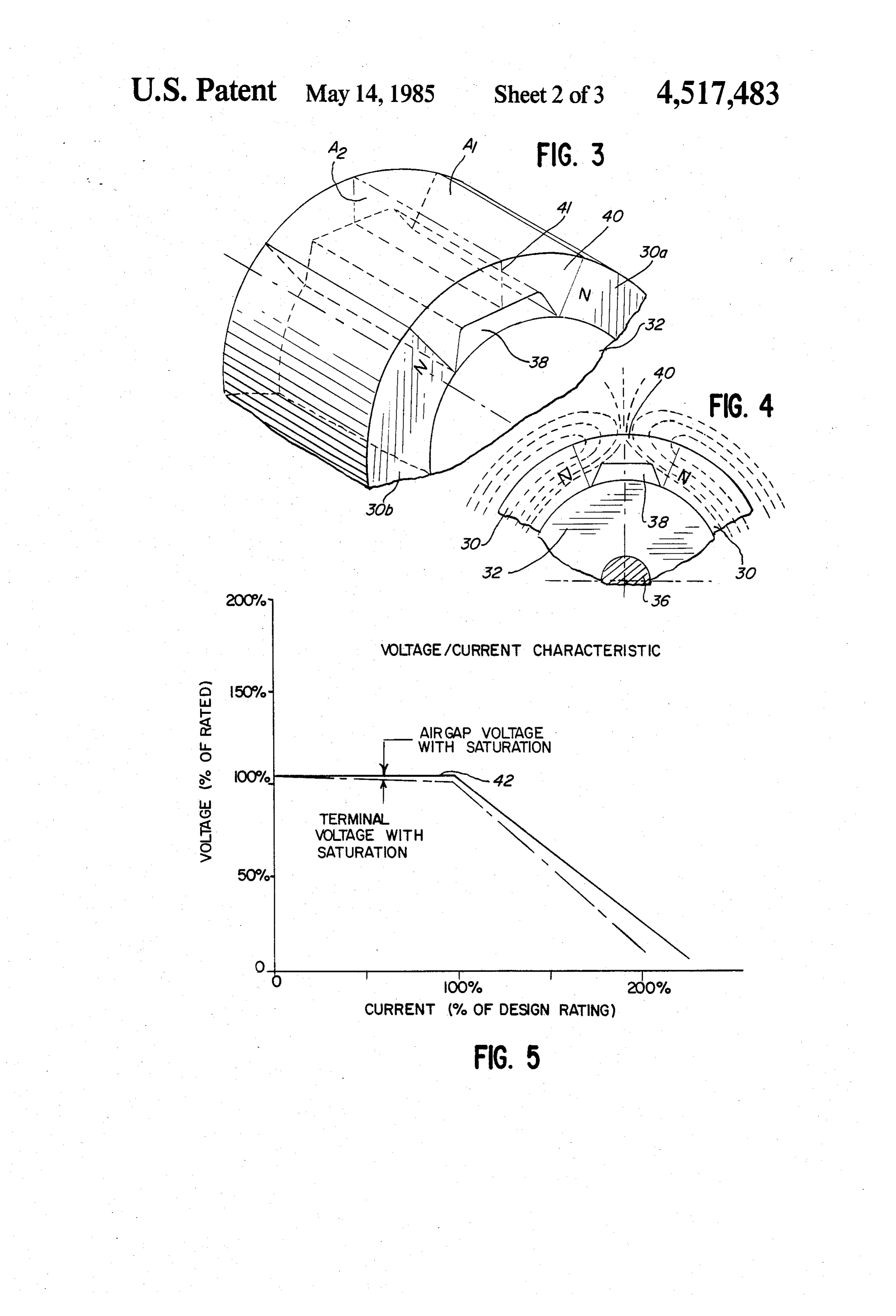
example, each of McCarty et al U.S. Pat. No. 4,242,610, FIG. 3 is a fragmentary perspective view of a rotor Silver U.S. Pat. No. 4,260,921 and Burgmeier et al U.S. magnetic structure for a permanent magnet generator Pat. Nos. 4,296,544 and 4,302,693 discloses a rotor as 40 rotor according to the present invention; sembly wherein tangentially magnetized magnets are FIG. 4 is a fragmentary elevational view of the mag separated by support members. The support members netic structure shown in FIG. 3;
have a plurality of generally equally spaced holes dis FIG. 5 is a graph of the voltage/current characteris posed near the periphery thereof to reduce the rotor tic for a PMG incorporating the magnetic structure mass and presumably allow the rotor to operate at high 45 shown in FIGS. 3 and 4;
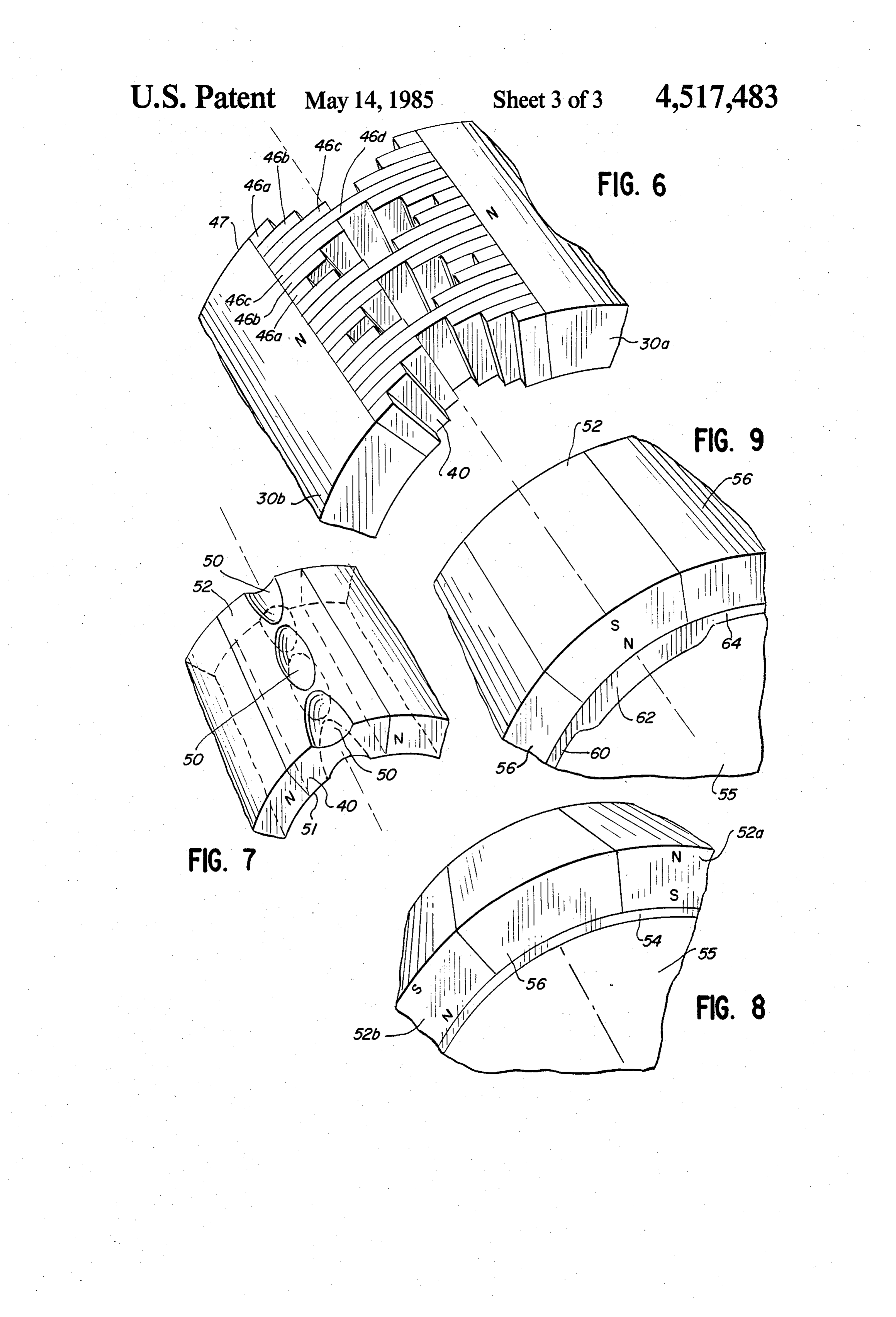
speeds. It is noted in these patents that the size and FIG. 6 is a fragmentary perspective view of a second location of the holes are established with regard to embodiment of the invention;
magnetic and structural considerations. However, there FIG. 7 is a fragmentary perspective view of a third is not even a recognition in these patents of the problem embodiment of the invention;
of variations in output voltage with changes in load 50 FIG. 8 is a fragmentary perspective view of a fourth current, and hence, no solution to this problem is pro embodiment of the invention for use in permanent mag posed in any of these patents. net generators utilizing radially magnetized magnets; and
DISCLOSURE OF INVENTION FIG. 9 is a fragmentary perspective view of a fifth In accordance with the present invention, a rotor 55 embodiment of the invention.
structure for a permanent magnet generator, or PMG, BEST MODE FOR CARRYING OUT THE includes means for limiting the voltage at low current INVENTION below a desired level.
In a first embodiment of the invention, a series of Referring now to FIGS. 1A and 1B, there is schemat tangentially magnetized magnets are equally spaced 60 ically illustrated a pair of prior art permanent magnet about the periphery of a nonmagnetic hub. Disposed in generators, or PMG’s 12,14, respectively. In FIGS. 1A the space between magnets is means for limiting the flux and 1B, common elements are designated by like refer developed by the magnets. In this first embodiment, flux ence numerals.
is limited by placing a ferromagnetic material having a Each PMG 12,14 includes a stationary stator 15 and a region of relatively small cross-sectional area between 65 rotor 16 which is rotatable with respect to the stator 15, the magnets so that flux density is increased to the satu as is conventional.
ration point of the below ferromagnetic material at all The rotor 16 includes either a plurality of tangentially current levels up to a maximum current level below polarized or magnetized magnets 17a in the PMG 12 or
Page 6
a plurality of radially polarized or magnetized magnets and low flux density. The material of the interpole mass 17b in the PMG 14. In the PMG's illustrated in FIGS. 40 is selected so that the magnetics saturate the inter 1A and 1B, the magnets are the high energy type having pole mass at the desired level to achieve the proper high coercive force and low flux density, such as samar voltage limiting. The interpole mass 40 is preferably ium cobalt. fabricated from a solid piece of magnetically saturable The magnets 17a of the PMG 12, FIG. 1A, are ferromagnetic material, preferably a ferromagnetic mounted on a hub 18 of nonmagnetic material which is alloy of iron, cobalt and vanadium with trace elements in turn secured to a shaft 19 driven by a prime mover marketed by Alleghany Ludlum Steel Corporation of (not shown). Disposed in the spaces between magnets Pittsburgh, Pa.. under the name Vanadium Permendur. 17a in the PMG 12 are bodies or spacers 22 of ferromag O The interpole mass 40 may alternatively comprise a netic material such as soft iron laminations, or the like. series of laminations, as described more specifically The magnets 17a, spacers 22 and stator 15 together below.
comprise a magnetic circuit to establish flux linkages, A retaining ring (not shown) may extend about the one of which is shown by the dotted lines in FIG. 1A. periphery of the rotor structure to maintain the place The magnets 17b of the PMG 14 are mounted on a 15 ment of the various parts, if desired.
hub 20 which is fabricated of ferromagnetic material The U-shaped interpole mass 40 cross-sectional area such as soft iron or the like to form a yoke. The hub 20 decreases from a cross-sectional area Al adjacent one of is secured to the shaft and is driven by a prime mover, the magnets 30a to a cross-sectional area A2 midway as noted in connection with FIG. 1A. Spacers 23 of between the magnet 30a and a second magnet 30b. This nonmagnetic material are disposed between the mag 20 decrease in cross-sectional area results in a greater flux nets 17b. The magnets 17b, hub or yoke 20 and stator 15 density in the region about area A2 than in the region of together comprise a magnetic circuit similar to that area A1. At a particular flux density, the ferromagnetic noted in connection with FIG. A. material of the interpole mass 40 saturates and thereby Referring now to FIG. 2, the voltage/current charac limits the flux in the series magnetic circuit comprising teristic for each of the PMG’s 12, 14 is illustrated. As the magnets 30, the interpole mass 40 and the stator (not shown by the solid line of FIG. 2, the voltage at the shown). As seen in FIG. 5, since output voltage is pro terminals of the PMG decreases approximately linearly portional to flux, the voltage of the device is likewise as a function of increasing current since the magnet flux maintained near a predetermined level for current levels decreases with increasing load current. Likewise, the less than 100% of the rated design point. This limiting "air gap" voltage, i.e. the voltage developed by the 30 of output voltage at low current levels means that the generator without regard to the internal resistance and circuitry connected to the output of the resulting PMG reactance of the stator windings also varies approxi need not be capable of tolerating wide voltage swings as mately linearly with changes in current. It can be seen was necessary with the prior art devices. Furthermore, from the graph of FIG. 2 that the terminal and air gap particularly where high energy magnetics are used such voltages increase substantially above rated voltage 35 as samarium cobalt, the resulting PMG can, with less when the current approaches zero. This is disadvanta weight and size, replace the heretofore known PMG geous since the load circuits connected to the output of exciter-generator arrangement.
the PMG must be capable of tolerating this wide fluctu As an example of the rotor structure shown in FIGS. ation in voltage with changes in current and/or a volt 3 and 4, assume that the flux density at the maximum age regulator must be used. 40 power point for the magnets is 4500 gauss and that In order to minimize the dependence of output volt Vanadium Permendur is the ferromagnetic material in age with output current, the magnetic structure of the the interpole volume 38. The cross-sectional areas Al present invention effectively imposes an air gap in the and A2 can be selected so that the flux density ap magnetic circuit by causing the permeability of the proaches 23.5 kilogauss as load current in the stator ferromagnetic material in the circuit to approach that of 45 windings of the PMG drops below 100% of rated cur air at a particular flux level. This is accomplished by rent. As load current continues to decrease and the appropriate dimensioning of the ferromagnetic material voltage or flux increases, the Vanadium Permendur in the magnetic circuit and/or by utilizing ferromag material saturates at a flux density slightly greater than netic materials which inherently saturate at a given flux 23.5 kilogauss and appear as a very long air gap in series density as noted more specifically below. 50 in the magnetic circuit.
Referring now to FIGS. 3 and 4, a magnetic structure It is desirable to have the break or "knee' 42 of the for the rotor of a PMG utilizing tangential magnets is curve representing air gap voltage to be as close as illustrated, only a portion of the magnetic structure possible to the maximum load point. This point is a being shown for purposes of clarity. The tangential function of PMG speed and magnet volume and is also magnetic structure shown in FIGS. 3 and 4 may be 55 related to the saturation parameters of the ferromag utilized in the PMG 12 in place of the rotor 16 shown in netic material of the flux limiting means.
FIG. 1A.
It is possible to limit flux in the stator of the PMG
As seen in FIGS. 3 and 4, a plurality of tangentially rather than in the rotor; however, controlling flux den magnetized magnets 30 are secured to a nonmagnetic sity in the stator is somewhat less efficient than rotor hub 32 which is in turn secured to a shaft 36. The mag 60 flux control since the stator flux density is changing at a nets 30 may be secured to the hub 32 by any suitable high frequency and the magnetics are driven relatively means such that an interpole volume 38 is created be hard into saturation leading to high losses in the core tween adjacent poles 30. Secured to the hub 32 in the material. Owing to the inherent nature of the PMG, it is interpole volume 38 is flux limiting means in the form of generally more desirable to control flux in the rotor, a U-shaped interpole mass 40 having a region of de 65 where the flux is continuous and saturation has no effect creased cross-sectional area 41. on efficiency.
In the preferred embodiment, the magnets are of the The embodiment shown in FIGS. 3 and 4 is preferred samarium cobalt type which has high coercive force for the tangential magnet arrangement since the outer
Page 7
surface of the magnets and interpole mass is cylindrical, the saturation point of the yoke material so that flux, thereby reducing windage and unbalance problems. and hence output voltage, are limited. Typically, this Other configurations can be utilized for the interpole would require that the yoke thickness be substantially mass 40, such as those shown in FIGS. 6 and 7. For less than the thickness of yokes disclosed in the prior example, as seen in FIG. 6, the interpole mass 40 may art, such as the magnetic hub shown in FIG. 1B. This comprise a series or stack of laminations 46 of varying reduction in thickness may lead to a reduction in length which when assembled together and placed in strength for the rotor assembly, and hence additional the interpole volume 38 act as flux limiting means in the means may be necessary to strengthen the rotor assem series magnetic circuit including the magnets 30, the bly to prevent deformation of the yoke 54 during use. stator of the PMG and the laminations 46. The lamina 10 Referring now to FIG. 9, there is shown an alterna tions 46 are of differing lengths or circumferential ex tive embodiment of a rotor structure for a PMG utiliz tent 46a-46d with the lamination 46a being the shortest ing radially magnetized magnets wherein the yoke 54 and the lamination 46d being the longest. The lamina shown in FIG. 8 is replaced by a yoke 60 of varying tions are bonded together in the pattern shown in FIG. thickness. In FIGS. 8 and 9, common elements have like 6 wherein the length or circumferential extent of suc 15 reference numerals. The yoke 60 includes relatively cessive laminations, starting at one axial end 47 of the thick portions 62 and thin portions 64. The thin portion rotor, increases up to the lamination 46d which tra 64 limits flux, and hence output voltage, as was noted verses the entire distance between adjacent magnets with respect to the embodiment shown in FIG.8. The 30a,30b. The length of successive laminations then de thick portions 62 provide additional support for the creases down to the shortest lamination 46a and the 20 magnetic structure on the yoke 60 to increase the sequence then repeats. The laminations are preferably strength and hence structural integrity of the rotor constructed of the Vanadium Permendur material pre assembly. In this case, the additional strengthening viously described. means which may be necessary with the embodiment of The lamination stack effects flux limitation due to the FIG. 8 may be dispensed with in certain applications. restriction in cross-sectional area between adjacent 25 Analogous to the previous embodiments, the flux magnets. The number and size of laminations may be limitation may be accomplished in various other ways in varied to achieve the proper flux saturation level. the yoke 54 or 60, such as by drilling holes or otherwise As seen in FIG. 7, the interpole mass 40 may alterna removing material at appropriate spaces in the series tively comprise a solid piece of ferromagnetic material, magnetic circuit, or by utilizing a material which satu such as Vanadium Permendur, having a series of inden 30 rates at a particular level, as was noted with respect to tations or dimples 50 which accomplish a reduction in the embodiments utilizing tangential magnets noted cross-sectional area which in turn limits flux and there above.
fore output voltage at low current levels. The indenta We claim:
tions 50 may be present on one or both of the radially 1. In a permanent magnet generator having a rotor inner and outer walls 51.52 respectively of the interpole 35 rotatable within a stator, the stator having windings mass 40, as desired. which develop output voltage in response to rotation of Other means or methods of reducing magnetic flux the rotor relative thereto, the output voltage being de may be utilized, such as by drilling holes, or otherwise pendent upon the level of current in the stator windings, selectively removing material to accomplish a cross a magnetic structure for reducing the dependence of sectional area reduction. 40 output voltage on the current in the stator windings, It should also be noted that flux limitation can be comprising:
accomplished without a dimensional change in cross a magnet on the rotor which develops magnetic flux sectional area by utilizing materials, such as iron or linking the stator windings; iron-nickel alloys, which saturate at a particular level. means connected in a magnetic circuit with the mag In such a case, the interpole mass 40 may be configured 45 net for limiting the flux developed thereby to main to minimize windage losses while at the same time pro tain the output voltage of the permanent magnet viding the desired voltage limitation at low current machine near a desired level substantially indepen levels. dent of current in the stator windings, wherein the Referring now to FIG. 8, there is shown an alterna flux limiting means includes a body of magnetically tive rotor assembly of the present invention for use in 50 saturable material having means for increasing the PMG's having radially magnetized magnets or poles 52. flux density therein to a saturation point to thereby As seen in FIG. 8, two of the magnets 52a,52b are se limit flux; and cured to a yoke 54. The yoke 54 is in turn connected to a second magnet spaced apart from the aforemen a nonmagnetic hub 55 which is in turn secured to a shaft tioned magnet and wherein the flux limiting means (not shown). 55 includes a plurality of magnetically saturable lami Disposed between the magnets 52a, 52b is a nonmag nations of different lengths, only some of the lami netic spacer 56. A retaining ring (not shown) may be nations traversing the entire space between the used, as before, to maintain the placement of the various magnets.
parts. 2. In a permanent magnet generator having a rotor The rotor assembly may be used in the PMG 14 60 rotatable within a stator, the stator having windings shown in FIG. 1B in place of the rotor 16. which develop output voltage in response to rotation of In this embodiment of the invention, the yoke 54 acts the rotor relative thereto, the output voltage being de as the means in which flux limiting is accomplished in pendent upon the level of current in the stator windings, the series magnetic circuit comprising the magnets 52, a magnetic structure for reducing the dependence of the yoke 54 and the stator of the PMG. The yoke mate 65 output voltage on the current in the stator windings, rial may be Vanadium Permendur, or any other suitable comprising: o material. In this case, the thickness of the yoke 54 is a magnet on the rotor which develops magnetic flux selected to cause an increase of flux density therein to linking the stator windings;
Page 8
means connected in a magnetic circuit with the mag in a magnetic circuit with the magnets for limiting net for limiting the flux developed thereby to main the flux therefrom to limit the output voltage at a tain the output voltage of the permanent magnet desired level; and machine near a desired level substantially indepen wherein the rotor includes a nonmagnetic hub, a dent of current in the stator windings; and 5 ferromagnetic yoke disposed about the hub and wherein the rotor includes a ferromagnetic yoke dis wherein the magnets are radially polarized and posed about the hub and wherein the magnet is connected in a magnetic series circuit with the radially polarized and connected in a magnetic yoke.
series circuit with the yoke. 7. The permanent magnet generator of claim 6, 3. The permanent magnet generator of claim 2, O wherein the yoke thickness is such that the yoke mate wherein the yoke thickness is such that the yoke mate rial saturates at a desired flux density so that the output rial saturates at a particular flux density so that the voltage is limited below a predetermined voltage. output voltage is limited to a point slightly greater than 8. The permanent magnet generator of claim 6, the output voltage at rated current and voltage for the wherein the yoke includes thin portions, the thin por machine. 5 tions limiting flux at a desired level. 4. The permanent magnet generator of claim 2, 9. In a permanent magnet generator, or PMG, for wherein the yoke includes thick and thin portions, the delivering current to a load, the PMG having a rotor thin portions limiting flux at a desired level. and a stator having windings, the rotor being rotatable 5. A permanent magnet generator having means for relative to the stator to develop output voltage which limiting output voltage at current levels below 100% of 20 varies as a function of load current, a magnetic structure design rating, comprising: on the rotor for limiting output voltage at low load a stator having stator windings which develop output current levels, comprising:
voltage; a plurality of spaced-apart tangentially magnetized a rotor disposed within the stator and rotatable with magnets for developing magnetic flux; and respect thereto, the rotor having a magnetic struc 25 means disposed in the space between adjacent mag ture including a plurality of spaced-apart magnets nets for establishing a magnetic circuit therewith which develop magnetic flux and means connected including a region of decreased cross-sectional area in a magnetic circuit with the magnets for limiting for increasing flux density to a point of saturation the flux therefrom to limit the output voltage at a to thereby limit the output voltage. desired level, the flux limiting means including a 30 10. In a permanent magnet generator, or PMG, for body of ferromagnetic material disposed between delivering current to a load, the PMG having a rotor the magnets including means for increasing flux and a stator having windings, the rotor being rotatable density to a point of saturation to thereby limit the relative to the stator to develop output voltage which output voltage wherein the body of ferromagnetic varies as a function of load current, a magnetic structure material includes a plurality of laminations of dif 35 on the rotor for limiting output voltage at low load ferent lengths, only some of the laminations tra current levels, comprising:
versing the entire space between adjacent magnets. a plurality of spaced-apart radially magnetized mag 6. A permanent magnet generator having means for nets for developing magnetic flux; and limiting output voltage at current levels below 100% of a ferromagnetic yoke disposed on the rotor con design rating, comprising: 40 nected in a magnetic series circuit with the plural a stator having stator windings which develop output ity of magnets including at least one portion suffi voltage; ciently thin so that the yoke material in such por a rotor disposed within the stator and rotatable with tion saturates at a particular flux density in turn respect thereto, the rotor having a magnetic struc causing the output voltage to be limited to a point ture including a plurality of spaced-apart magnets 45 below a particular voltage.
which develop magnetic flux and means connected sk ck ck ck :k
Provenance
- Collection
- Cited prior art
- Original PDF
- patentimages.storage.googleapis.com →
- Filed
- 1983-12-27
- Pages
- 8
- Method
- pdftotext (the PDF's own text layer) + pdftoppm 300dpi page scans
- Source
- Google Patents bibliographic record
- Granted
- 1985-05-14
- Inventors
- David J. Hucker; Donald A. Straznickas; Sundstrand Corp
- Transcribed from
- patentimages.storage.googleapis.com →