patent · US6064123
Horizontal axis wind turbine
16 May 2000
Page 1 — bibliographic record
United States Patent (19) 11 Patent Number: 6,064,123 Gislason (45) Date of Patent: May 16, 2000 54) HORIZONTALAXIS WIND TURBINE 1944,239 1/1934 Honnef ...................................... 290/55 4,289.970 9/1981 Deibert ... ... 290/44 76 Inventor: Nils Erik Gislason, Lyngholt 2, 4,302,684 11/1981 Gogins ........... ... 290/55 Akuneyri, Iceland 4.323,331 4/1982 Schachle et al. ........................... 416/9 s 4,330,714 5/1982 Smith ........................................ 290/55 21 Appl. No.: 09/051,554 5,299,913 4/1994 Heidelberg .......................... 416/197 A 22 PCT Filed: Oct. 13, 1995 Primary Examiner Nicholas Ponomarenko Attorney, Agent, or Firm-Richard C. Litman 86 PCT No.: PCT/IB95/00871 57 ABSTRACT
A horizontal axis wind turbine comprises a rotor-Supporting
S 102(e) Date: Apr. 10, 1998 framework, a multi-vaned rotor, an electricity-generating Stator, and a rotation track. The Supporting framework is 87 PCT Pub. No.: WO97/13979 constructed with a plurality of triangular Sub-units. The rotor PCT Pub. Date:Apr 17, 1997 has a plurality of Vanes projecting therefrom. The Vanes 7 have adjustable pitch and are encircled by a rim having a 51) Int. Cl.' ........................................................ F03D 5/04 plurality of magnets. Wind induces rotation of the rim. The 52) U.S. Cl. ................................................. 290/55; 290/44 Stator is essentially Stationary and is mounted on the frame 58 Field of Search .......................................... 290/44, 55 work opposite the rim. AS magnets on the rotating rim pass by the Stator, electricity is generated. The Stator uses the pull 56) References Cited of the magnets to automatically adjust itself to align with the
So that the framework can continually be adjusted to maxi 717,939 1/1903 Hernandez. mize wind-induced rotation of the rotor.
1,233,232 7/1917 Heyroth. 4 Claims, 4 Drawing Sheets
size 7-zzzzz
ST Tef 2NZaz-e-Zaas
SSGR TNYXNITN
Page 2
Drawing sheet — no readable text.
Page 3
Drawing sheet — no readable text.
Page 4
Drawing sheet — no readable text.
Page 5
Drawing sheet — no readable text.
Page 6
HORIZONTALAXIS WIND TURBINE conventional blades is expensive. Moreover, the increased rotor diameter of horizontal axis wind turbines makes blade
BACKGROUND OF THE INVENTION control and Structural integrity difficult at high wind Speeds. The need arises for a horizontal axis wind turbine of 1. Field of the Invention
Simple construction, low production cost, low maintenance
The present invention relates generally to turbines for cost, and Sound Structural integrity. creation of electrical power, and more specifically to hori U.S. Pat. No. 145,970, issued to Emilius Sanderson, on Zontal wind turbines. Dec. 30, 1873, shows the concept of supporting two sides of 2. Description of the Prior Art a horizontal axis of a wind-wheel.
Throughout history, civilization has yearned for better and U.S. Pat. No. 273,182, issued to Homer B. Sprague, on more efficient Sources of power generation. Fossil fuels have J.Feb. 27, 1883, and U.S. Pat. No. 5,161,952, issued to Alfred Eggers, Jr., on Nov. 10, 1992, show use of a rim having not always locally available and have been expensive to spokes to Support blades. These patents also show an aero transport over long distances. Nuclear power has produced unwanted radioactive waste and carries potential for apoca dynamiconto blade shape, as well as the use of blades threaded spokes.
lyptic accidents. Solar power's promise has been dimmed by 15 the high cost of equipment necessary to utilize the Sun's Jul.U.S. Pat. No. 282,122, issued to Carl F. W. Schramm, on 31, 1883, shows a windmill that automatically adjusts to energy. Hydroelectric power generation requires flowing changes in wind Speed.
water and, often, disruption of normal paths of water. U.S. Pat. No. 717,939, issued to Luis Soria Y Hernandez, Seemingly, the wind is the only readily available and Safe on Jan. 6, 1903, shows a wind turbine rotating on a wheeled Source of power. base.
Though developed centuries ago, wind-powered devices are thus still a favored Source of power generation today. The Jan.U.S. Pat. No. 1,015,416, issued to Judson A. Bennett, on windmill, once used to grind grain, has been adapted to ends of a1912, 23, shows a frame structure which supports both horizontal shaft on which is mounted a windmills produce electricity. Windmills have evolved into wind tur bines wherein the wind's power no longer turns Stone 25 Vanes. The center post remains fixed as the outer corners follow a circular track to allow rotation.
wheels atop grain, but rather passes magnets alongside wire coils to generate electricity. In wind turbines, the winds Jul.U.S. Pat. No. 1,233,232, issued to Albert H. Heyroth, on force pushes the blades of a wheel which act as the rotors of Honnef, 1917,
on Jan. 23, 1934, and British Patent Document No.
a generator.
507,555, issued to Clement Lean, on Jul. 13, 1939, show use
Over time, wind turbines have been developed to work of a rim of a blade Structure, in conjunction with a fixed more efficiently in compensating for many of the natural Stator Section, to generate electricity. obstacles impeding consistent energy recovery from the U.S. Pat. No. 4,323,331, issued to Schachle et al., on Apr. wind. For example, Shifts in wind direction can Stop a fixed 6, 1982, shows a frame structure in which a turbine Support wind turbine; thus, wind turbines have been constructed 35 is rotatably mounted on a ground-based Support member. with various rotational methods so that the wind will strike
U.S. Pat.
the blade in the optimum fashion. Further, wind turbines Dec. 21, 1982, shows No. 4,364,708, issued to Constant V. David, on have been developed whereby fluctuations in wind velocity a windmill having adjustable blades. leave the wind turbine relatively unaffected in both struc Singly None of the above inventions and patents, taken either tural integrity and power generation potential. or in combination, is seen to describe the instant 40 invention as claimed.
Horizontal axis wind turbine generators have proven very effective in producing electricity from the wind. Typically, SUMMARY OF THE INVENTION they consist of a nacelle mounted atop a tall tower. The A horizontal axis wind turbine, according to the present nacelle houses a transmission to increase a rotor's rotational invention, comprises a rotor-Supporting framework, a multi Speed to the Speed of an electrical generator, Some means of 45 Vaned rotor, an electricity-generating Stator, and a rotation power Smoothing is necessary to compensate for cyclic track. The Supporting framework is constructed with a fluctuation and wind gusts. The nacelle also incorporates a plurality of triangular Sub-units. The rotor has a plurality of Strong Shaft to carry a large rotor hub and blades. Turning in Vanes projecting from a central hub rotatably mounted on a horizontal plane, the nacelle adjusts to the direction of the the Supporting framework. The Vanes have adjustable pitch wind current to face the rotor into the oncoming wind. 50 and are encircled by a rim having a plurality of magnets. Horizontal axis wind turbines are not without their Wind induces rotation of the rim. The stator is essentially problems, however. The transmission requires regular main Stationary and is mounted on Supports that attach the Stator tenance and repair, a major expense in horizontal axis wind to the framework opposite the rim. The Supports on which turbine design is the transmission. Furthermore, the main the Stator is mounted adjust to ensure a constant distance shaft must withstand not only the load of the rotor hub and 55 between the rim and the Stator, regardless of movement of blades, but also the load from Oscillations and wind gusts. the rim. The attraction between the rotor rim magnets and Additionally, expenses are incurred in reinforcing the tower the Stator maintains the Stator in alignment with the rotor. Structure Supporting the heavy nacelle. The stator is able to move into alignment with the rotor Another problem with horizontal axis wind turbines is because the Supports fleX but remain parallel to the rotor maximizing rotor diameter and the number of rotor blades. 60 axis. This is a major feature of the present invention. AS Horizontal wind turbine generators usually have a rotor magnets on the rotating rim pass by the Stator, electricity is diameter of at least 20 meters, and they are designed with generated. The framework is mounted on the rotation track only two or three blades. As a general rule, if a wind turbine So that the framework can continually be adjusted to maxi has a large number of blades, the rotor's Solidity is mize wind-induced rotation of the rotor.
increased, rotation speed is slower, and leSS noise is pro 65 Accordingly, it is a principal object of the invention to duced. Horizontal axis wind turbines have employed few provide a wind-driven electrical generator with minimal blades, however, because the design and construction of mechanically inter-engaging parts.
Page 7
It is another object of the invention to provide stator The bottom end B of the first one 34 of the middle leg Supports that adjust to maintain a constant distance and members is connected to the bottom end B of the first one alignment between mobile magnets and a Stator. 42 of the forward leg members, and at this connection, there It is a further object of the invention to use a plurality of is disposed a first rotatable wheel 48 dimensioned and spokes to ensure a rigid rim for maintaining positions of configured to engage the rotation track 18. The bottom end each Vane of a plurality of Vanes projecting from a rotor. B of the second one 36 of the middle leg members is connected to the bottom end B of the second one 44 of the
Still another object of the invention is to provide a simple yet Sturdy, adjustable frame work for Supporting a rotor and forward leg members, and at this connection, there is stator of a wind turbine. attached and disposed a second rotatable wheel 50 dimen It is an object of the invention to provide improved Sioned and configured to engage the rotation track 18. elements and arrangements thereof in an apparatus for the nected Two horizontal strengthening members 52, 53 are con purposes described which is inexpensive, dependable and to and disposed centrally between the middle leg fully effective in accomplishing its intended purposes. members 34, 36 and the forward leg members 42, 44, respectively. Two angled Strengthening members 54 each
These and other objects of the present invention will 15 become readily apparent upon further review of the follow havingand a first end 56 and a second end 58 are connected to disposed between the middle leg members 34, 36 and ing Specification and drawings. the forward leg members 42, 44. The first ends 56 of the BRIEF DESCRIPTION OF THE DRAWINGS angled Strengthening members 54 are connected to the first one 42 of the front leg members and the first one 34 of the
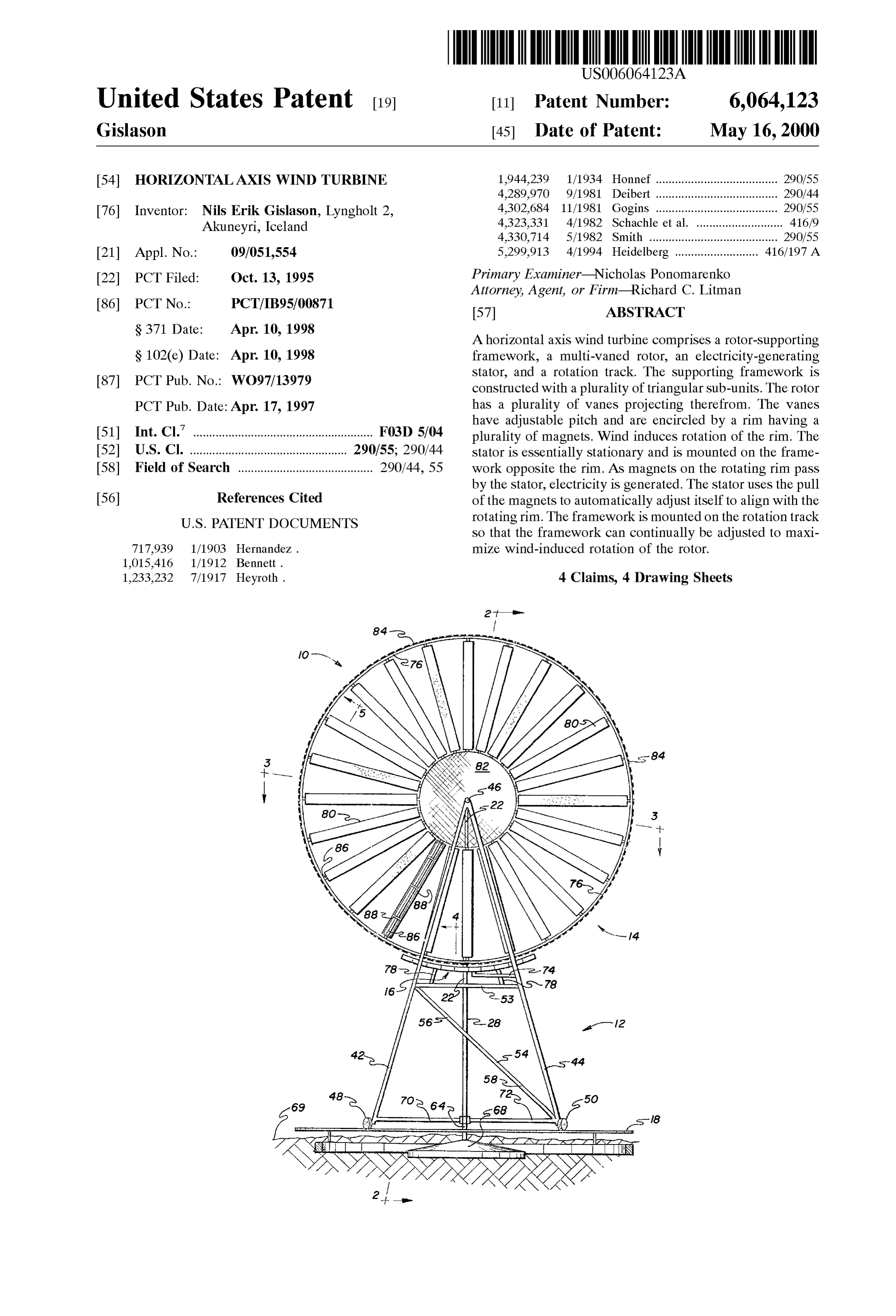
FIG. 1 is a front elevational view of the present invention, middle leg members, respectively, at about the same place as shown with portions of the invention projecting below the the horizontal Strengthening members 52, 53 are connected. Surface of the earth. The second ends 56 of the angled strengthening members 54 FIG. 2 is a side section view of the present invention. are connected to the Second one 44 of the front leg members and the second one 36 of the middle leg members,
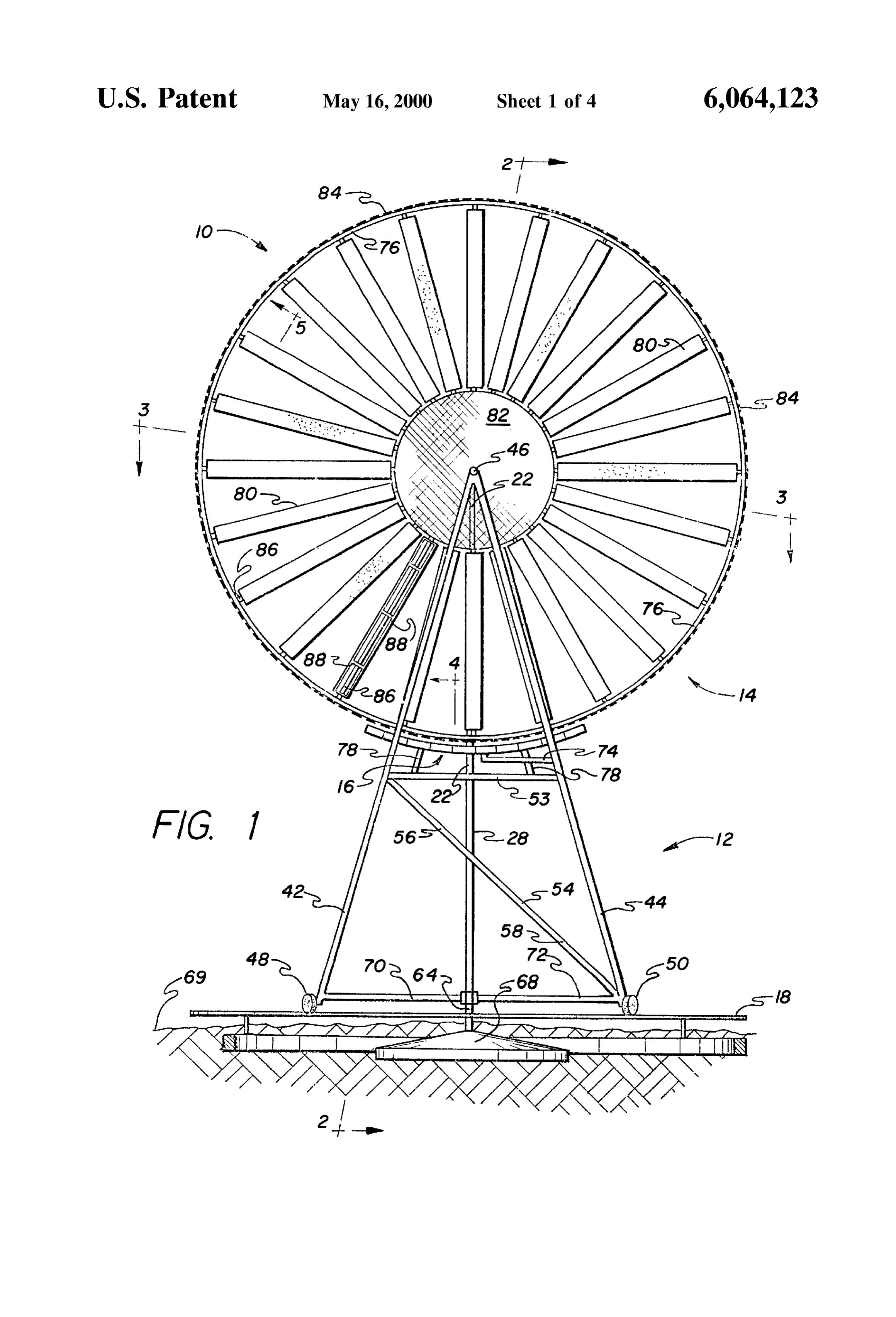
FIG. 3 is a top section view of the present invention. 25 respectively,
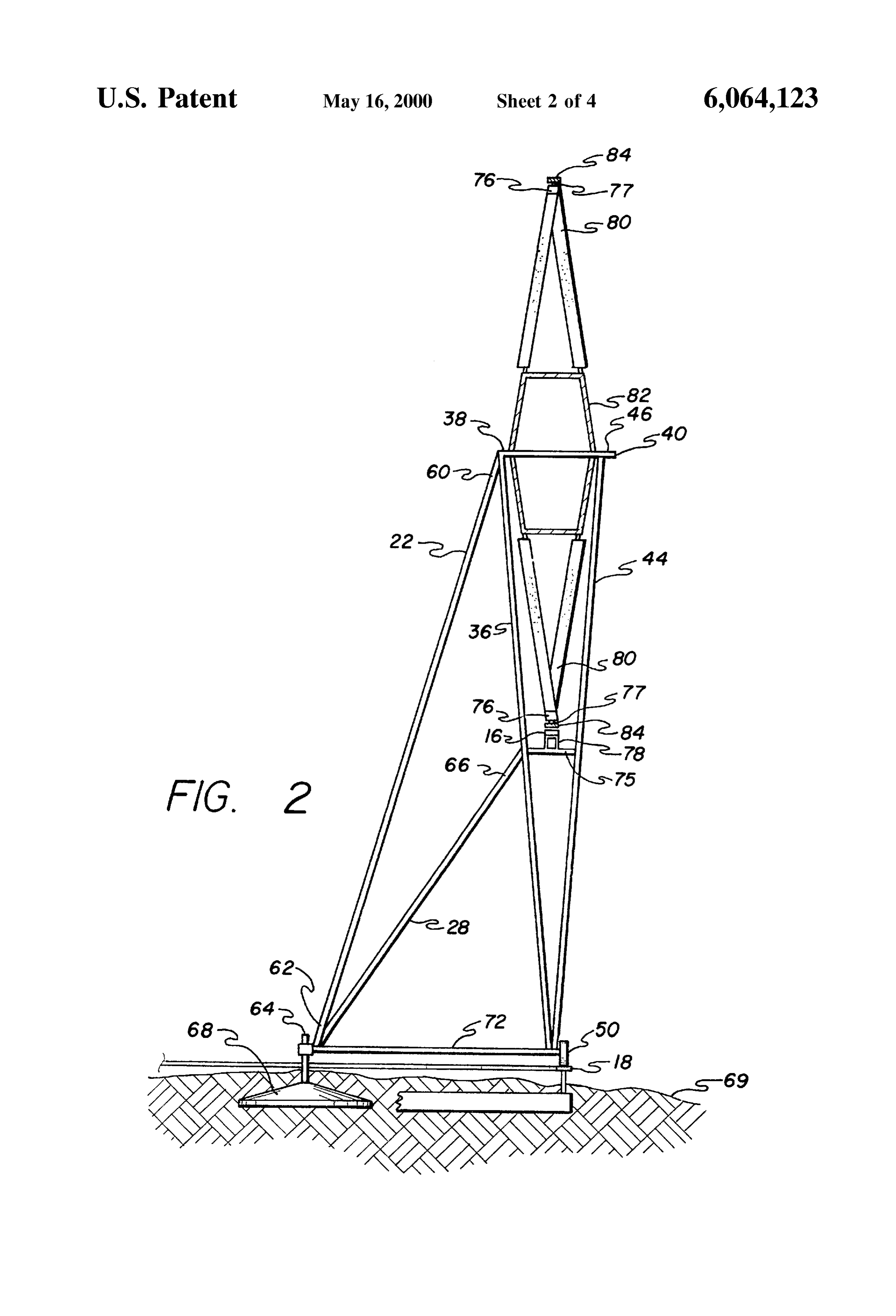
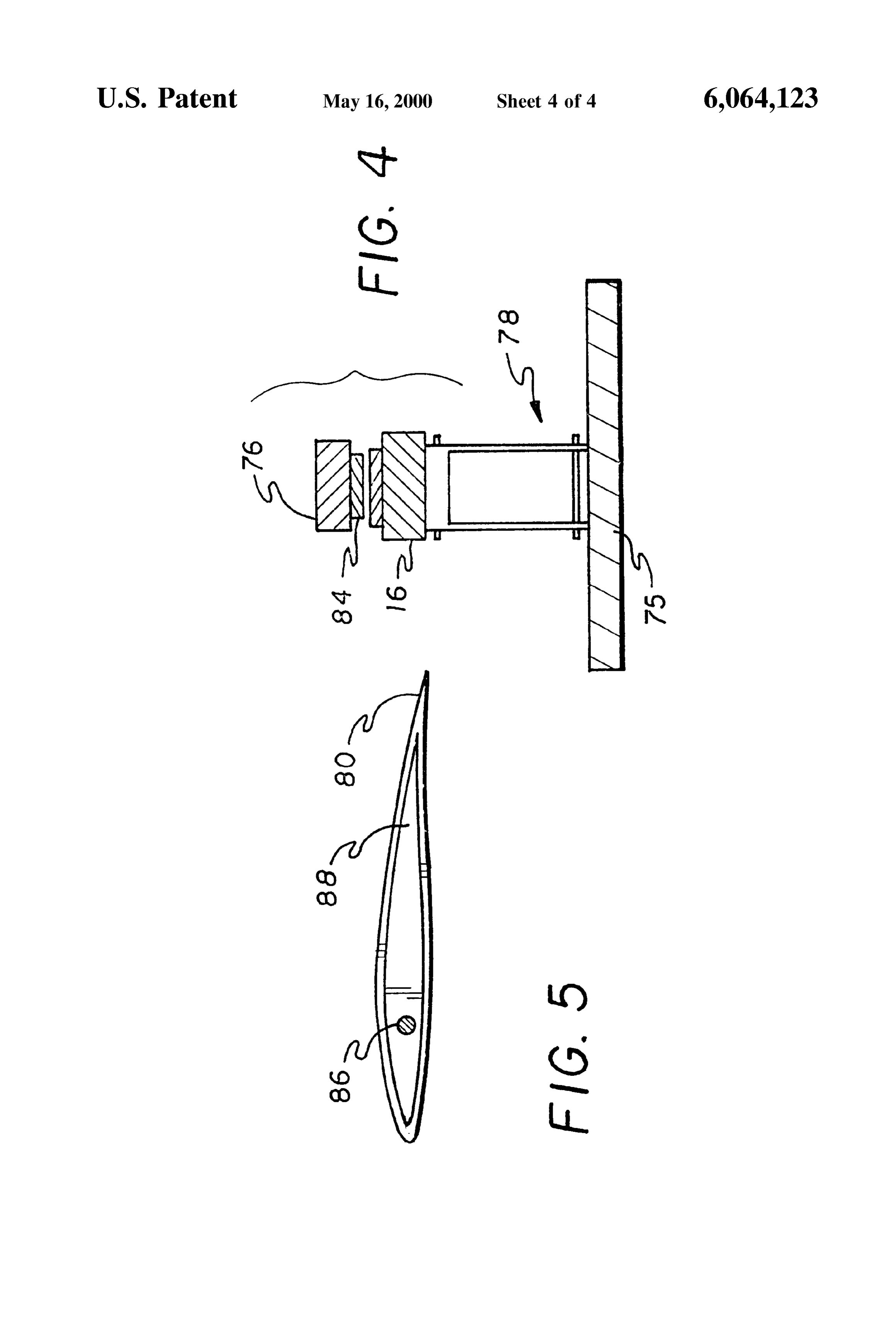
FIG. 4 is a detail Section view of a rim-stator-framework at about the same place as the Second rotatable wheel 50 is attached.
region of the present invention. The major rear leg member 22 is connected at a first end FIG. 5 is a section view of a vane and a spoke on which 60 to the top ends T of the two middle leg members 34, 36, the Vane is mounted. and a Second end 62 of the major rear leg member 22 is Similar reference characters denote corresponding fea rotatably connected to a central turbine rotation shaft 64. tures consistently throughout the attached drawings. The minor rear leg member 28 is connected at a first end 66
DETAILED DESCRIPTION OF THE
to a central point (not shown) on a rear horizontal Strength
PREFERRED EMBODIMENT
ening member 52, and a Second end of the minor rear leg
member 28 is rotatably connected to the central turbine
The present invention is a horizontal axis wind turbine rotation shaft 64. Various further strengthening members that minimizes mechanical wear, Simplifies wind turbine (not shown) may be disposed between the major rear leg construction, and provides mechanisms for ensuring consis member and the middle leg members, or between other members of the framework.
tent spacing between rotated magnets and an electricity generating Stator, despite flexing effects of wind, and attrac 40 Because of the rotatable connection of the framework 12 tive forces of the magnets on the Stator. with the rotation shaft 64, and the rotatable nature of the Referring to the drawings, a horizontal axis wind turbine wheels 48 and 50 that engage the rotation track 18, the 10 according to the present invention comprises a rotor framework 12 can continually be adjusted to maximize Supporting framework 12, a multi-vaned rotor 14, an wind-induced rotation of the rotor 14. This adjustment is electricity-generating Stator 16, and a rotation track 18. 45 accomplished by a linkage or control System of known type The rotor-Supporting framework 12, includes a plurality (not shown).
of triangular sub-units formed by structural members. More The rotation shaft 64 is connected to a heavy central Specifically, there are at least five vertical leg members, anchor member 68 of known type that is disposed centrally including a major rear leg member 22, two middle leg with respect to the rotation track 18. The anchor member 68 members 34, 36, and two forward leg members 42, 44. 50 is supported by or imbedded in ground 69. Two horizontal Optionally and preferably, there is also a minor rear leg base members 70, 72 are connected between the rotation member 28. Each leg member is thin, elongated and com shaft 64 and the bottom ends B of the middle leg members posed of a Sturdy, durable, light-weight material of known 34, 36 and the forward leg members 42, 44. These base type. In one embodiment, each leg member is a piece of members 70, 72 further strengthen the framework 12. Standard, thin-walled Steel tubing. Each leg member also has 55 There is at least one front-back Stator Support mechanism a top end T and a bottom end B. A first one 34 of the middle 74 mounted on the framework 12, Such as on the forward 42, leg members joins a Second one 36 of the middle leg 44 and/or middle 34, 36 leg members, for providing support members at the top ends T thereof. The top ends T of the to the stator 16, the front-back stator support mechanism 74 middle leg members 34, 36 Support a rear end 38 of a being dimensioned and configured to fleX in directions hub-shaft 40 rotatably disposed on and connected by known 60 parallel with the rotor 14, while maintaining the stator 16 a means to the top ends T of the middle leg members 34, 36. constant distance from a rim 76. There is also at least one A first one 42 of the forward leg members joins a Second one Side-side Stator Support mechanism 78, preferably two, 44 of the forward leg members at the top ends Tthereof. The mounted on the framework 12, Such as on one or both of the top ends T of the forward leg members 42, 44 support a horizontal strengthening members 52, 53 or on horizontal forward end 46 of the hub-shaft 40 rotatably disposed on and 65 stator support members 75. The two horizontal stator Sup connected by known means to the top ends T of the forward port members 75 are positioned between horizontal strength leg members 42, 44. ening members 52, 53 So as to provide a greater Structural
Page 8
S 6 integrity. This Side-Side Stator Support mechanism 78 pro It is to be understood that the present invention is not vides Support to the Stator 16, and is dimensioned and limited to the Sole embodiment described above, but encom configured to flex in directions parallel with the rim 76, passes any and all embodiments within the Scope of the while maintaining the Stator a constant distance from the rim 5 following claims.
What is claimed is:
1. A horizontal axis wind turbine comprising:
The multi-vaned rotor 14 includes a plurality of vanes 80 a rotor-Supporting framework, projecting from a hub 82 rotatably mounted on the hub shaft a rotor Supported by Said framework, Said rotor including, 40. The hub 82 may be left open so that the wind can blow a plurality of Vanes, through it, as shown, or the hub 82 may be left closed so that a rim encircling Said Vanes, and the wind will blow around it through the vanes 80. Together, a plurality of magnets Secured to Said rim; the vanes 80 are encircled by the rim 76, which has a a Stator; and plurality of magnets 84 disposed outside the rim 76, relative a Stator Support mechanism attaching Said Stator to Said to the vanes 80. In the preferred embodiment, thin steel 15 framework opposite Said rim, said Stator Support shims 77 are disposed between the magnets 84 and the rim mechanism including flex means for maintaining Said 76. The vanes 80 have adjustable pitch. Preferably, there are Stator and Said rim of the rotor in alignment during movement of Said rim.
as many Vanes 80 as practicable in order to reduce the 2. The horizontal axis wind turbine according to claim 1, necessary StiffneSS and therefore weight and cost of the rim further including:
76. The number and width of the vanes 80 can be varied to a plurality of Spokes equal in number to Said plurality of maximize the efficiency of the wind turbine 10 for the wind Vanes, and envelope of the area. a generally circular hub rotatably mounted on a shaft, Said There is a plurality of spokes 86 equal in number to the plurality of Spokes being connected to and tensioned plurality of vanes 80 on the hub 82 mounted on the hub shaft 25 between Said hub and Said rim, Said Vanes being 40. The plurality of spokes 86 is connected to and tensioned mounted on Said Spokes.
between the hub 82 and the rim 76, with the vanes 80 3. The horizontal axis wind turbine according to claim 1, mounted on the spokes 86. The vanes 80 are dimensioned where 4. A each of Said Vanes has an adjustable pitch.
horizontal axis wind turbine according to the present and configured to rotate about the spokes 86 and thus the invention comprising:
vanes 80 have adjustable pitch. Pitch of the vanes 80 is a rotor-Supporting framework including a major rear leg controlled by a linkage of known type (not shown). member, two middle leg members, two forward leg Preferably, the vanes 80 are substantially hollow and are members, and a minor rear leg member, each leg constructed of light-weight, durable material, Such as fiber member having a top end and a bottom end, a first one glass and sheet metal. Ribs 88 disposed in the vanes 80 35 of Said middle leg members joining a Second one of Support the Vanes 80 and ensure proper spatial relationship Said middle leg members at Said top ends thereof, Said between the spokes 86 and the vanes 80. top ends of Said middle leg memberS Supporting a rear end of a hub-shaft rotatably disposed on and connected
The electricity-generating Stator 16 is attached to the to Said top ends of Said middle leg members, a first one framework 12 opposite the rotating rim 76, whereby the 40 of Said forward leg members joining a Second one of plurality of magnets 84 on the rotating rim 76 pass by the Said forward leg members at Said top ends thereof, Said stator 16, when wind induces rotation of the rotor 14, top ends of Said forward leg members Supporting a thereby generating electricity by induction. In order to forward end of said hub-shaft rotatably disposed on and maintain proper control of the Spatial relationship between connected to Said top ends of Said forward leg the stator 16 and the rotor 14, it is desirable that the stator 45 members, said bottom end of said first one of Said 16 not circumscribe more than ninety degrees of the rim 76. middle leg members being connected to Said bottom Preferably, the stator circumscribes less than forty-five end of Said first one of Said forward leg members, a first degrees of the rim 76. rotatable wheel disposed at said bottom end of said first one of Said forward leg members, Said bottom end of
It is important to maintain a constant Voltage, regardless 50 Said Second one of Said middle leg members being of what wind load is impinging on the Vanes. One way to connected to Said bottom end of Said Second one of Said maintain constant Voltage is to vary the Spatial orientation of forward leg members, a Second rotatable wheel being the stator 16 with respect to the rotor 14 according to disposed at Said bottom end of Said Second one of Said variations in the wind load. Specifically, the stator 16 can be forward leg members, two horizontal Strengthening moved away from the rotor 14 in order to decrease Voltage 55 members being connected to and disposed centrally output, and, conversely, moved closer to the rotor 14 in order between Said middle leg members and Said forward leg to increase Voltage. In this case, the Stator 16 is dimensioned members, two horizontal Stator Support members posi and configured to Selectively move nearer to and farther tioned between Said horizontal Strengthening members, from the rim 76 (and magnets 84) of the rotor 14. two angled Strengthening members each having a first 60 end and a Second end and being connected to and
Alternately, it is possible to have a plurality of taps (not disposed between Said middle leg members and Said shown), each tap connected to different portions of induction forward leg members, Said first ends of Said angled windings (not shown) in the Stator 16, So that each tap (not Strengthening members being connected to Said first shown) produces a different voltage. Then, as wind loads one of Said forward leg members and Said first one of varies, a tap (not shown) having the desired Voltage is 65 Said middle leg members, respectively, at Substantially Selected by known means, and Voltage is thus maintained at where Said horizontal Strengthening members are an approximately constant level. connected, Said Second ends of Said angled Strengthen
Page 9
ing members being connected to Said Second one of a rotation track, Said rotation shaft being connected to a Said forward leg members and Said Second one of Said heavy central anchor member disposed centrally with middle leg members, respectively, at about where Said respect to Said rotation track, two horizontal base rotatable wheel is attached, said major rear lea member members being connected between Said rotation Shaft being connected at a first end thereof to Said top ends and Said bottom ends of Said middle leg members and of Said two middle leg members, and a Second end of of Said forward leg members, whereby Said base mem Said major rear leg member being rotatably connected bers further Strengthen Said framework, Said framework to a central turbine rotation shaft, Said minor rear leg being mounted, via Said wheels on Said rotation track member being connected at a first end to a central point whereby said framework is continually adjusted to on a rear one of Said horizontal Strengthening members, maximize wind-induced rotation of Said rotor; and a Second end of Said minor rear leg member being an electricity-generating Stator attached to Said frame rotatably connected to Said central turbine rotation work opposite Said rim, whereby Said plurality of shaft; magnets on Said rim pass by Said Stator, when wind a multi-vaned rotor, including a plurality of Vanes pro induces rotation of Said rotor, thereby generating elec jecting from a hub rotatably mounted on Said hub shaft, 15 tricity by induction, Said Stator circumscribing about Said Vanes being encircled by a rim having a plurality forty-five degrees of Said rim, Said Stator being dimen of magnets, said magnets being connected to Said rim Sioned and configured to Selectively move nearer to and by thin Steel Shims, Said rotor further including a farther from said rim of said rotor; plurality of Spokes equal in number to Said plurality of at least one front-back Stator Support mechanism mounted Vanes on Said hub mounted on Said hub shaft, Said on Said forward and middle leg members, Said front plurality of Spokes being connected to and tensioned back Stator Support mechanism being dimensioned and between said hub and Said rim, with Said Vanes configured to fleX for maintaining alignment of Said mounted on Said spokes, Said Vanes being dimensioned Stator with Said rim during movement of Said rim; and and configured to rotate about Said Spokes thereby at least one Side-side Stator Support mechanism mounted having adjustable pitch, Said Vanes being Substantially 25 on Said horizontal Stator Support members, Said Side hollow and constructed of light-weight, durable Side Stator Support mechanism being dimensioned and material, Selected from fiberglass and sheet metal, Said configured to fleX for maintaining alignment of Said Vanes having ribs disposed in Said Vanes, said ribs stator With said rim during movement of said rim. Supporting Said Vanes and ensuring proper spatial rela tionship between said spokes and Said Vanes, k k k k k
Provenance
- Collection
- Cited prior art
- Original PDF
- patentimages.storage.googleapis.com →
- Filed
- 1995-10-13
- Pages
- 9
- Method
- pdftotext (the PDF's own text layer) + pdftoppm 300dpi page scans
- Source
- Google Patents bibliographic record
- Granted
- 2000-05-16
- Inventors
- Nils Erik Gislason
- Transcribed from
- patentimages.storage.googleapis.com →