patent · US5315159
Wind turbine
24 May 1994
Page 1 — bibliographic record
United States Patent (19) 11 Patent Number: 5,315,159 Gribnau (45) Date of Patent: May 24, 1994 (54) WINDTURBINS Uwe Hansen, Germany Patent 3402035, Jul. 25, 1985, (75) Inventor: Wilhelmus H. J. K. Gribnau, English abstract.
Hengelo, Netherlands McAllister, Alternating Current Motors, 1909, pp.
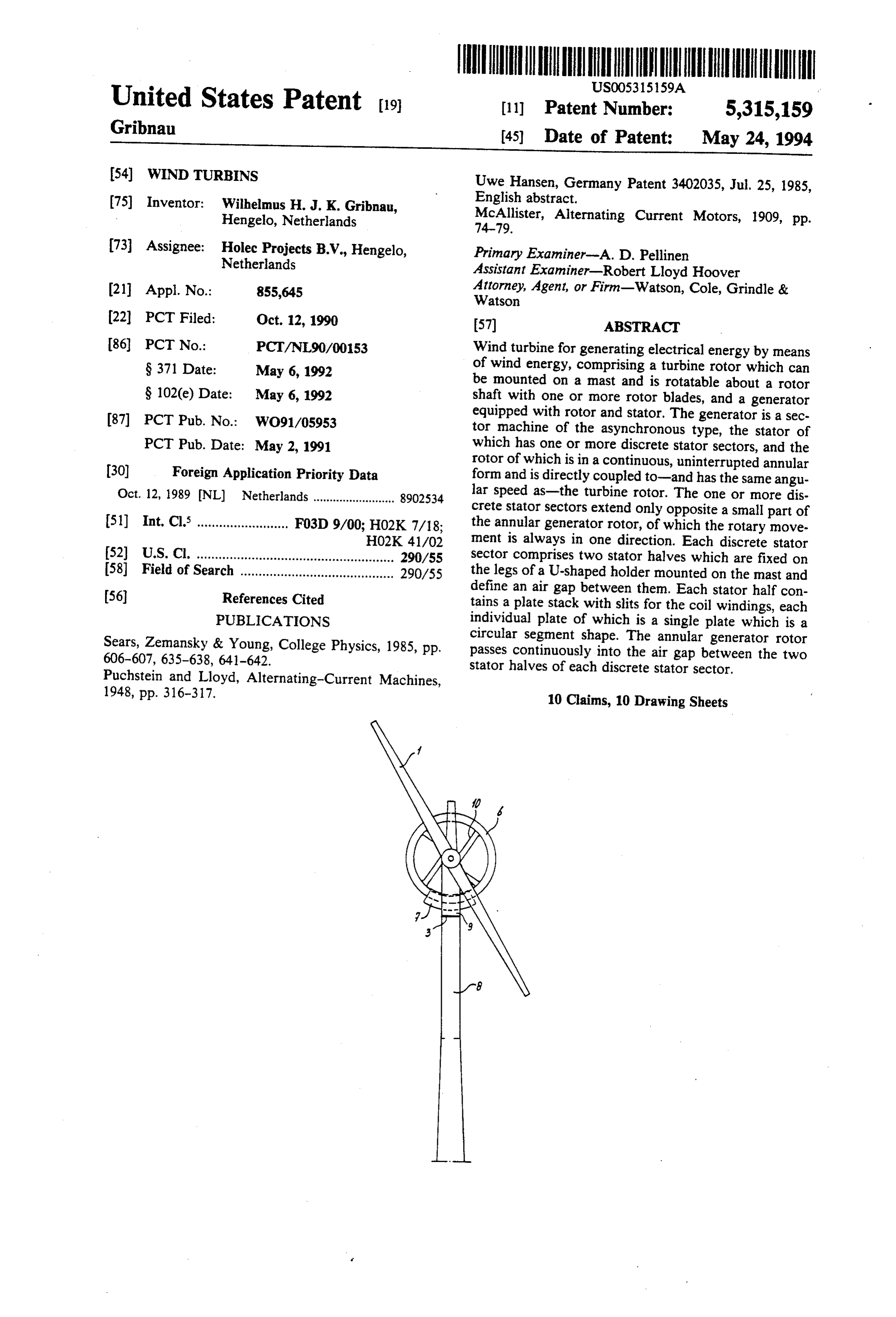
73) Assignee: Holec Projects B.V., Hengelo, Primary Examiner-A. D. Pellinen Netherlands Assistant Examiner-Robert Lloyd Hoover 21 Appl. No.: 855,645 Attorney, Agent, or Firm-Watson, Cole, Grindle & Watson (22) PCT Filed: Oct. 12, 1990 57) ABSTRACT (86 PCT No.: PCT/NL90/001.53 Wind turbine for generating electrical energy by means S371 Date: May 6, 1992 of wind energy, comprising a turbine rotor which can be mounted on a mast and is rotatable about a rotor
S 102(e) Date: May 6, 1992 shaft with one or more rotor blades, and a generator 87 PCT Pub. No.: WO91/05953 equipped with rotor and stator. The generator is a sec tor machine of the asynchronous type, the stator of
PCT Pub. Date: May 2, 1991 which has one or more discrete stator sectors, and the 30) Foreign Application Priority Data rotor of which is in a continuous, uninterrupted annular form and is directly coupled to-and has the same angu
Oct. 12, 1989 NL Netherlands ......................... 8902534 lar speed as-the turbine rotor. The one or more dis crete stator sectors extend only opposite a small part of 51) Int. Cl. ......................... F03D 9/00; HO2K 7/18; the annular generator rotor, of which the rotary move HO2K. 41/02 ment is always in one direction. Each discrete stator 52 U.S. Cl. ...................................................... 290/55 sector comprises two stator halves which are fixed on 58) Field of Search .......................................... 290/55 the legs of a U-shaped holder mounted on the mast and (56) References Cited define an air gap between them. Each stator half con tains a plate stack with slits for the coil windings, each
PUBLICATIONS individual plate of which is a single plate which is a Sears, Zemansky & Young, College Physics, 1985, pp. circular segment shape. The annular generator rotor 606-607, 635-638, 641-642. passes continuously into the air gap between the two stator halves of each discrete stator sector.
Puchstein and Lloyd, Alternating-Current Machines, 1948, pp. 316-317. 10 Claims, 10 Drawing Sheets
Page 2
Drawing sheet — no readable text.
Page 3
Drawing sheet — no readable text.
Page 4
Drawing sheet — no readable text.
Page 5
Drawing sheet — no readable text.
Page 6
Drawing sheet — no readable text.
Page 7
Drawing sheet — no readable text.
Page 8
Drawing sheet — no readable text.
Page 9
Drawing sheet — no readable text.
Page 10
Drawing sheet — no readable text.
Page 11
Drawing sheet — no readable text.
Page 12
WIND TURBINS
generator with a large number of poles and therefore large diameter is integrated in the tower structure. This generator is driven directly by the wind turbine in this
The invention relates to a wind turbine for generating case. The generator concerned here is of the synchro electrical energy by means of wind energy, which wind nous type with permanent magnets, and built in the turbine comprises a turbine rotor which is to be conventional manner as a round, rotationally symmetri mounted on a mast and is rotatable about a rotor shaft cal ring machine. Such a machine has, however, as with one or more rotor blades, and a generator disadvantages the use of expensive magnets and the equipped with rotor and stator. Such a wind turbine is large diameter of the stator on which, as a result of the known in practice, for example from the Holec bro 10 low angular speed of the wind turbine with high pole chure "Wind turbine type WPS 30-3 for wind farm number, they have to be designed. As a result of the application", 1987. large diameter and relatively low axial length of the For various reasons, including environmental aspects stator, these machines are expensive, and are mechani and shortage of energy, wind energy has already been cally fragile, due to their lack of adequate round rigid used for a long time now for the supply of electricity in 15 ity.
thinly populated areas. The wind turbines used here are The object of the invention is to eliminate the above being built in increasingly large numbers and sizes. A mentioned problems and provide a wind turbine which problem here is the low energy content of the medium is a strong, simple design without conversion train, and air. The power output of a wind turbine is in fact di rectly dependent on the wind-catching surface of the 20 ais long thereby more reliable and easier to maintain, and has service life.
turbine rotor equipped with one or more blades, so that This is achieved according to the invention in a wind large turbine rotors have to be used. As a result of the turbine of the type mentioned in the preamble in that high peripheral speed of the ends of such large turbine the generator is a sector machine of the asynchronous rotors, the maximum achievable speed of rotation is type, of which the stator comprises one or more dis limited, inter alia, by material aspects such as strength, 25 crete stator sectors, and of which the rotor is in a con material fatigue etc., the shape and number of the rotor tinuous, uninterrupted annular form and is directly cou blades, and environmental aspects such as noise nui pled to the turbine rotor, one or more discrete stator sance. This means that the available speed of ratation on sectors extending only opposite a small part of the annu the turbine rotor will be a factor of 10 to 30 times lower lar generator rotor, of which the rotary movement is than in the case of a conventional generator. 30 always in one direction. The above-mentioned genera Since the power output of a generator is directly tor rotor can be in the form of a ring lying at right proportional to the speed, measures have to be taken to angles to the plane of the turbine rotor blades or a flat increase the speed or to adapt the generator to the low ring, i.e. open disc, extending in-or parallel to-the speed. This adversely affects the price per unit of power plane of the turbine rotor blades. supplied. As a general rule, it can be said that the price 35 According to the invention, use is made of a sector per unit of power supplied is related to the weight of the machine of which the one or more discrete stator sec plant, i.e. the heavier the plant, the higher the price of tors are of compact construction, and in which the the power supplied. In order, nevertheless, to be able to generator rotor coupled directly to the turbine rotor work with conventional high-speed generators and to can be produced with a freely selectable large diameter. obtain a reasonable power output, in the state of the art In this way a high peripheral speed with low angular many wind turbines are coupled by means of intermedi speed, i.e. with low speed of rotation, can be obtained. ate shafts, geared transmissions, couplings and brakes to If the rotor diameter is selected larger, the stator can be these high-speed generators. In this way the low speed selected smaller for generation of still the same amount of rotation of the wind turbine is adapted by means of a of power. The invention makes use of a sector machine mechanical gear or up-converter to the much higher 45 of the asynchronous type. This makes a simple and speed of rotation of the standard three-phase generator. robust annular construction of the generator rotor pos The above-mentioned conversion components are gen sible. This rotor can be made of a relatively cheap elec erally accommodated in a heavy and bulky gondola on trically conducting material. Due to the fact that the the top of the mast for the wind turbines. rotor diameter can be large, the air gap in the discrete In particular in the case of wind turbines for greater SO stator sectors comprising two stator halves can also outputs, for example above 100 kW, it has been found in advantageously be greater.
practice that in operation they are highly susceptible to Another advantage obtained is that, due to the fact serious defects and require frequent maintenance. The that an asynchronous machine which is inherently ro susceptibility to faults of the above-mentioned conver bust is used for the generator, the exciter(s), excitation sion train (turbine rotor, shafts, intermediate shafts, 55 system, regulator(s) and slip rings or rotary rectifiers couplings, gearbox, brake and generator) has become normally used are absent. This asynchronous machine increasingly clear. The complexity of the conversion can also advantageously be used as a brake by means of train makes this train sensitive to the difficult conditions direct current or capacitor excitation on one or more of wind turbine operation, such as vibrations, reso stator phase windings. When, for example, a vertical nances, great force and couple variations. 60 shaft turbine is initially started up, the asynchronous In order still to achieve the same power output at low machine as motor can run the wind turbine up to full speeds of wind turbines without conversion by means of speed from the stationary position. The asynchronous a whole conversion train, the generator can also be sector generator also naturally has a great slip, so that adapted. This can be achieved by, for example, increas the rotational speed dynamical behaviour of the wind ing the number of poles in the generator. This leads in 65 mill is better. For the removal of frost and/or ice, the turn to an increase in the dimensions of the generator. generator stator as a rotor at stand still can be heated up German patent publications DE-3629872 A1 and DE by means of intermittent or reverse switching on. The 3638129A1 give examples of a wind turbine in which a above-mentioned stator windings are connected to a
Page 13
three-phase transformer generally fitted at the bottom of homopolar voltages, as a result of which the phase in the mast of the wind turbine. This transformer is windings in the stator cannot be delta connected, but connected, for example, to the mains for the supply of also a system of inverse voltages. Conversely, in the power thereto or, in the event of e.g. starting up from a case of supply from a symmetrical three-phase network stationary position, for taking supply therefrom. 5 of which the phase voltages form a symmetrical system, As a result of the direct coupling between turbine a system of inverse currents also occurs. The size of rotor and generator, the mechanical gear or up-con these inverse currents depends on the length of the verter with their couplings and intermediate shafts are machine and the slip in the operation point concerned. not needed. This greatly improves the reliability of the All this is as mentioned in various publications, such as wind turbine, so that the use of wind energy with the 10 the manual "Drehstroniinear-motoren', 3rd revised aid of this wind turbine for the generation of electrical edition, Dr. Alfred Hithig Verlag, Heidelberg, by Prof. energy has become commercially attractive. Peter-Klaus Budig.
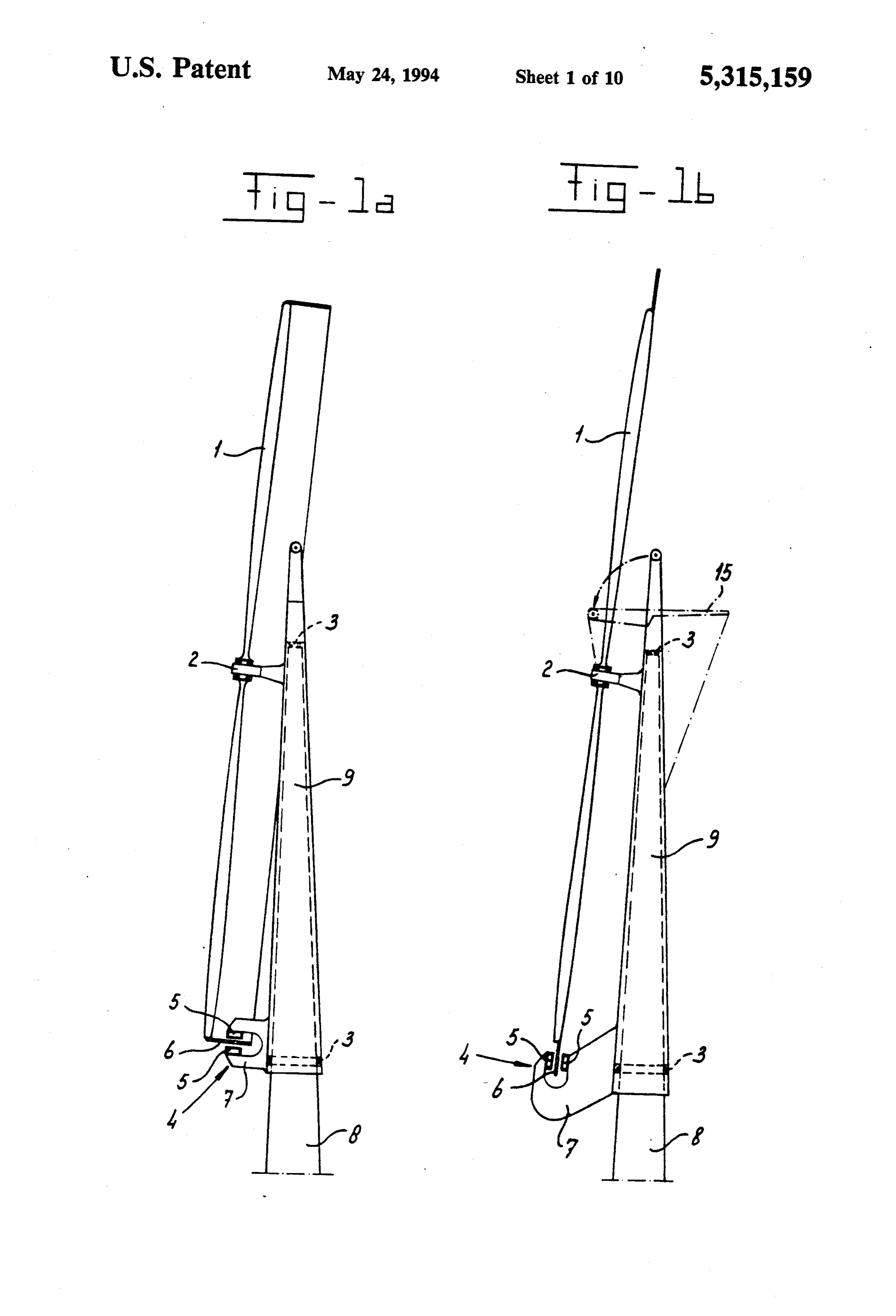
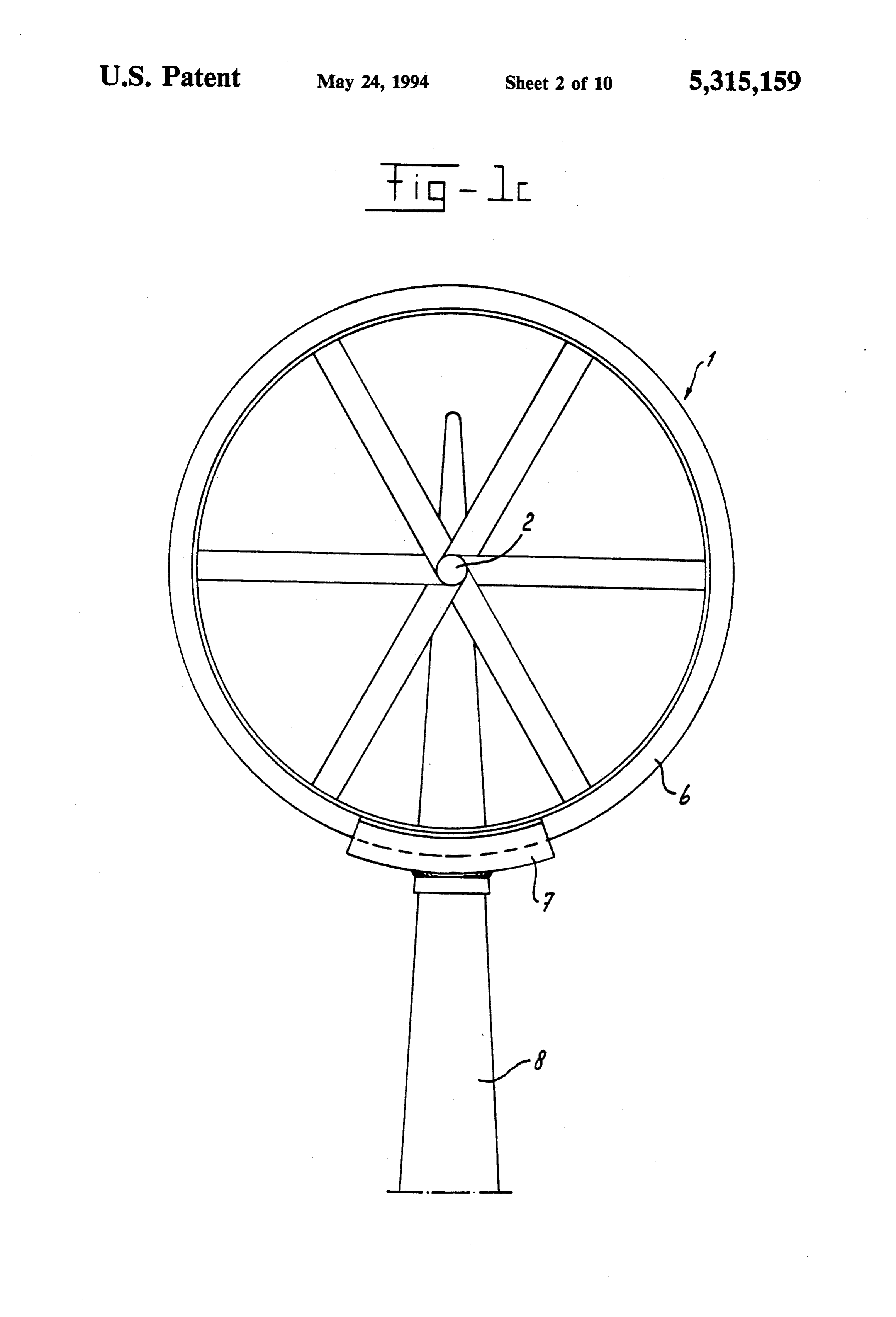
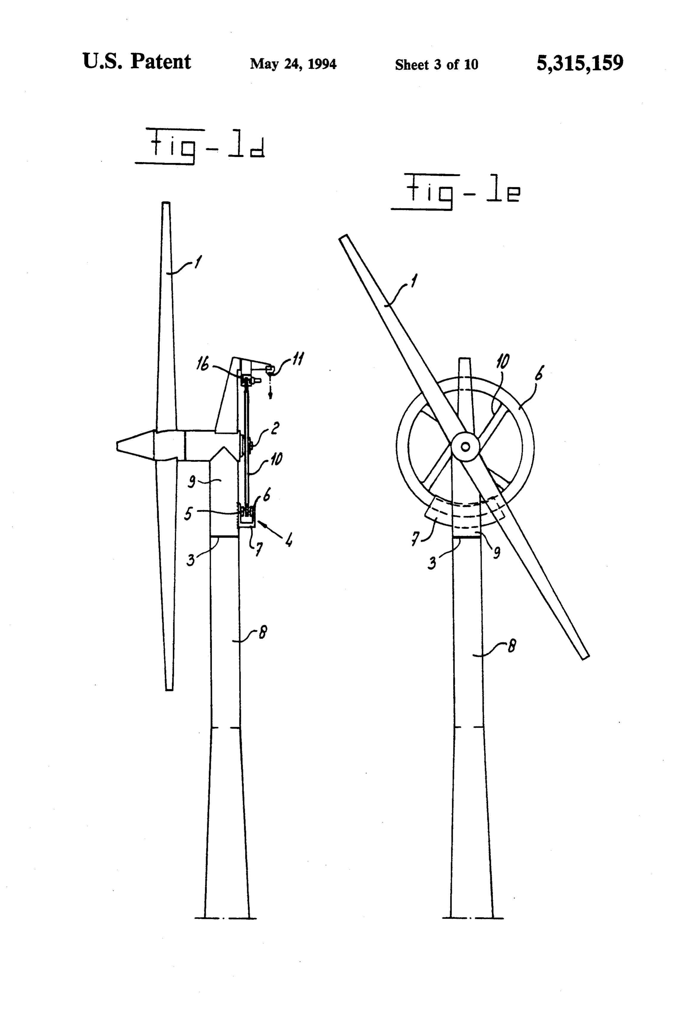
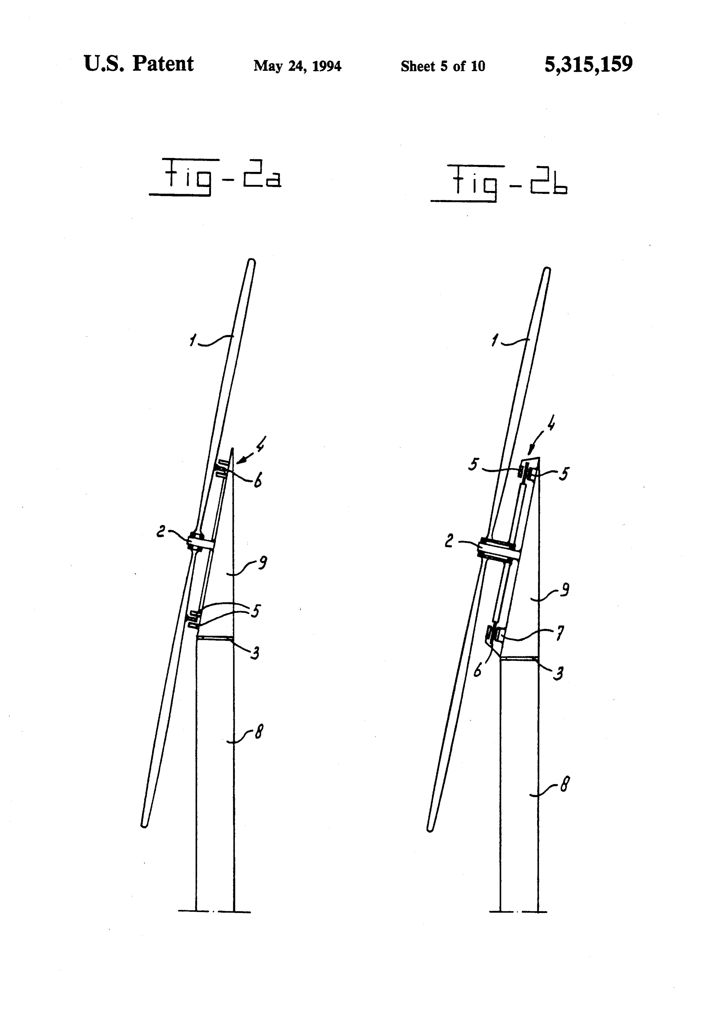
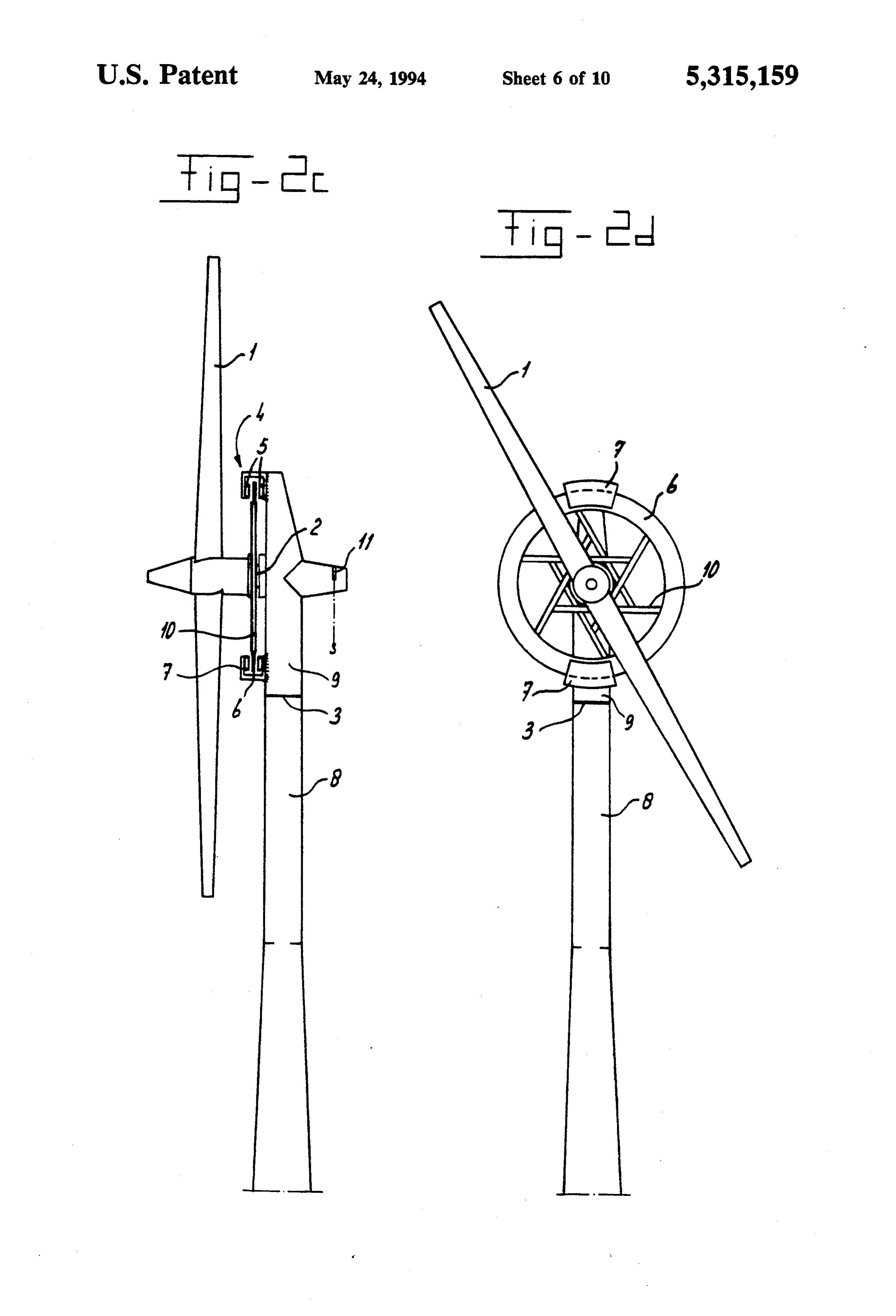
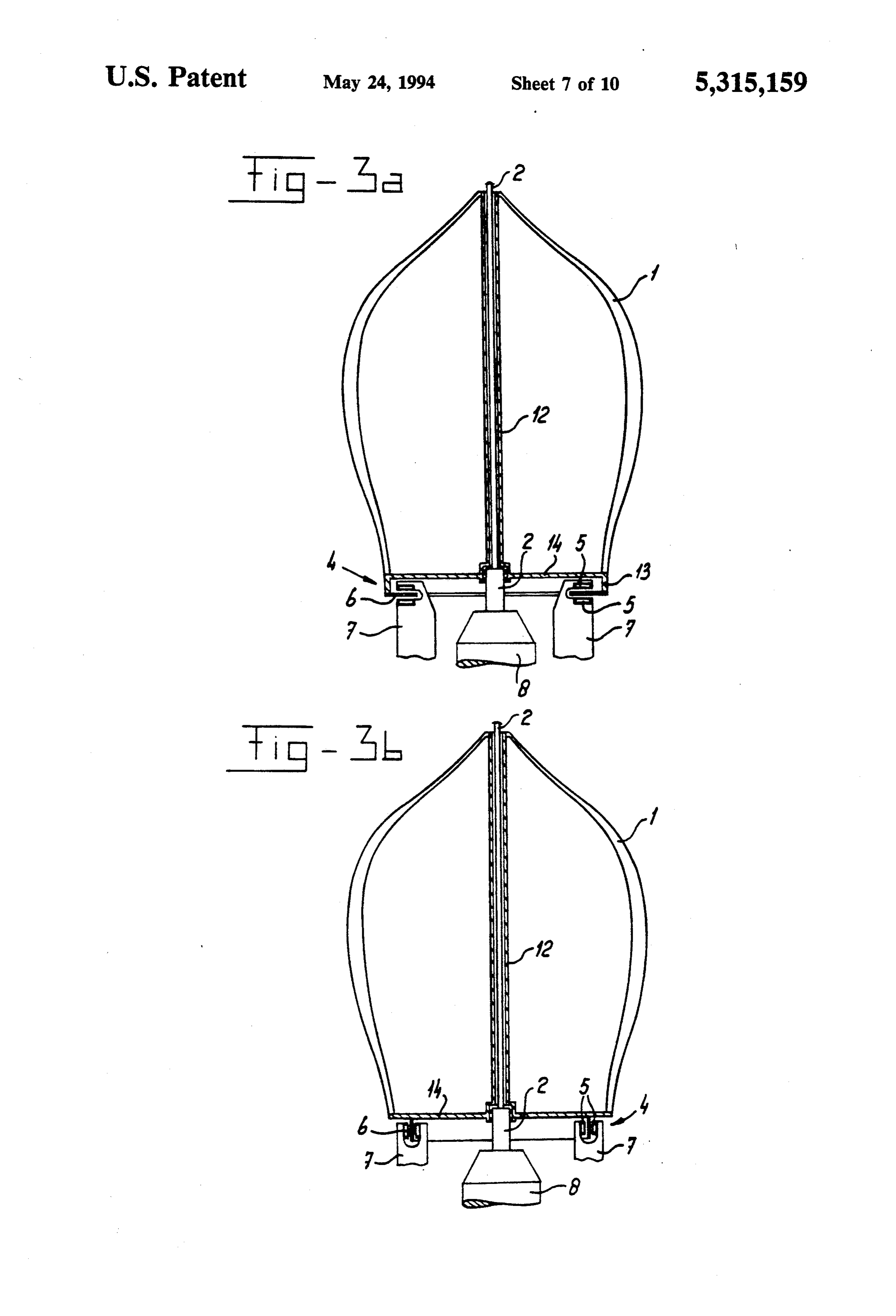
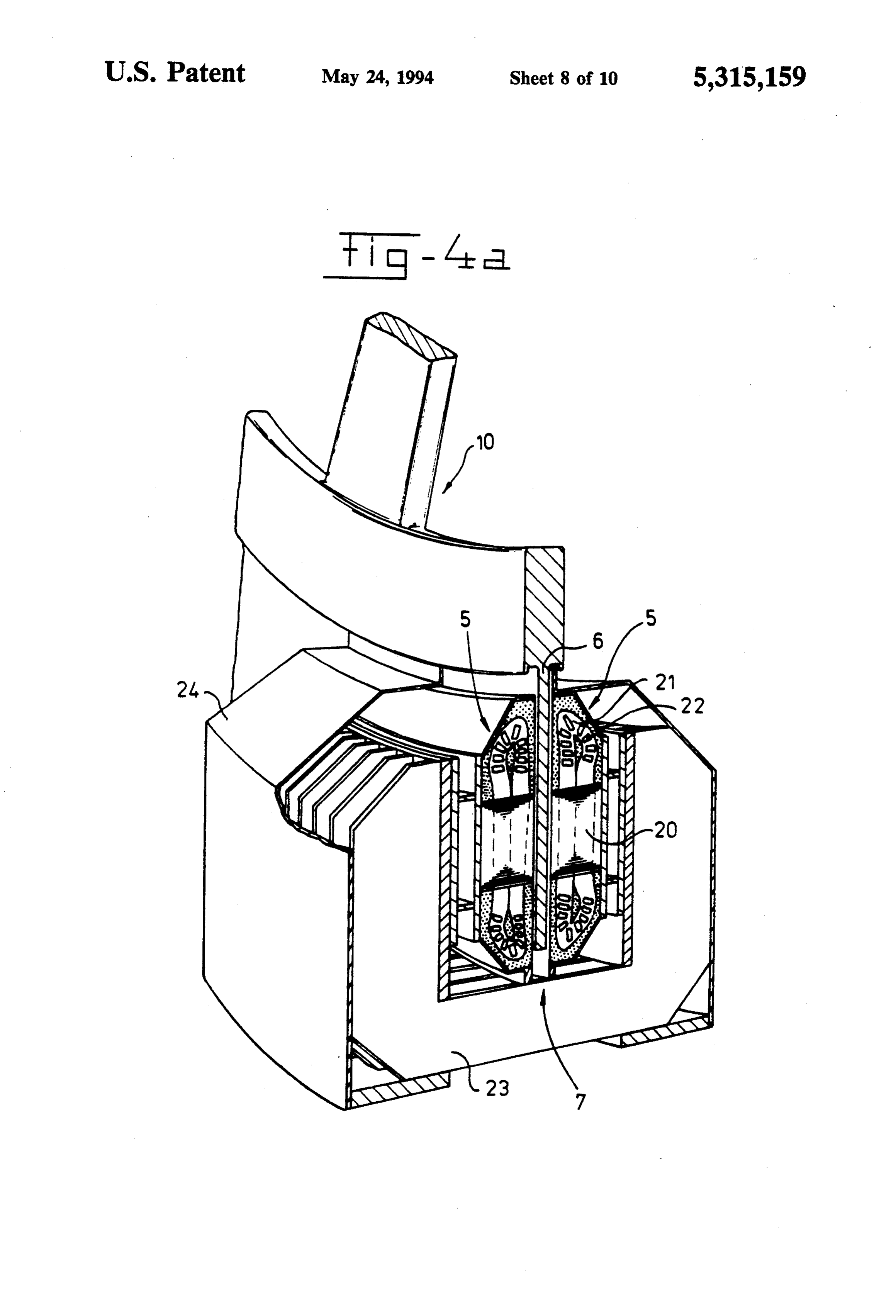
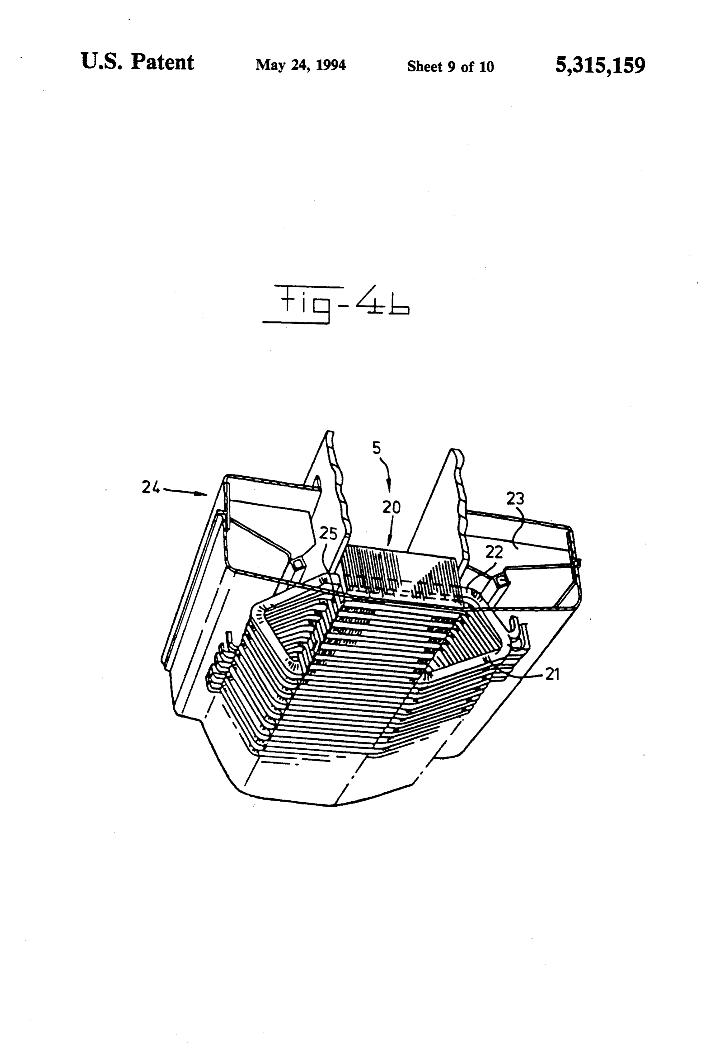
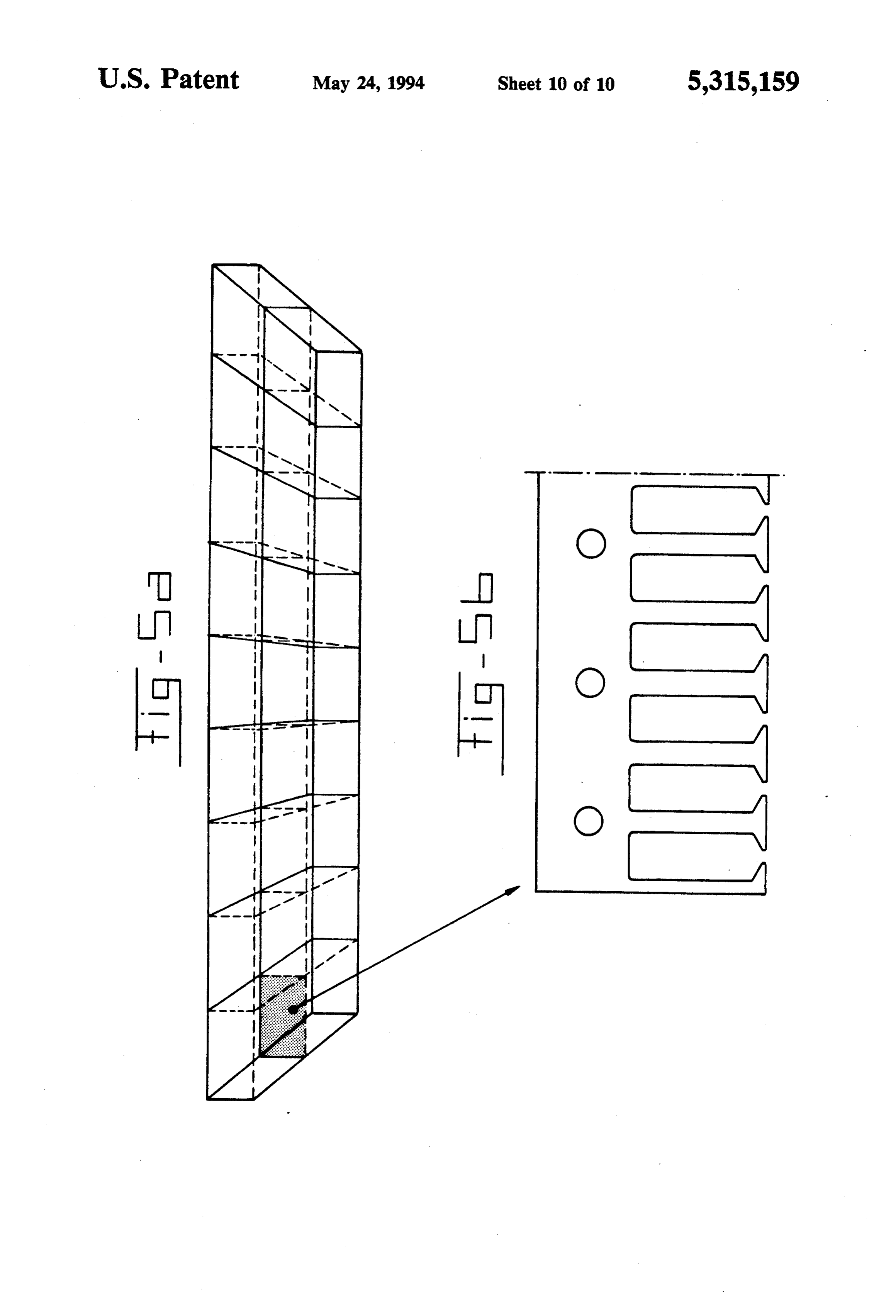
The above-mentioned design of the generator as a The fact that the above-mentioned Offenlegungss sector machine of the asynchronous type corresponds chrift is concerned only with a generator of the syn to the principle of a linear machine. Although this prin- 15 chronous type also emerges from FIGS. 1 and 3, in ciple has already been known for a long time, the use of which the rotor disc is equipped with permanent mag linear machines for outputs above 100kW has remained nets and is therefore a machine of the synchronous type. limited purely to the field of motors for driving or trac The invention will be explained in greater detail with tion, where stator and rotor move linearly along each reference to a number of examples of embodiments other. For a wide use of these drive motors, a number of 20 shown in the drawings, in which the same parts in the problems have proved extremely irksome, namely the different figures are indicated by the same reference high starting propelling forces, the magnetic floating of numbers, and in which:
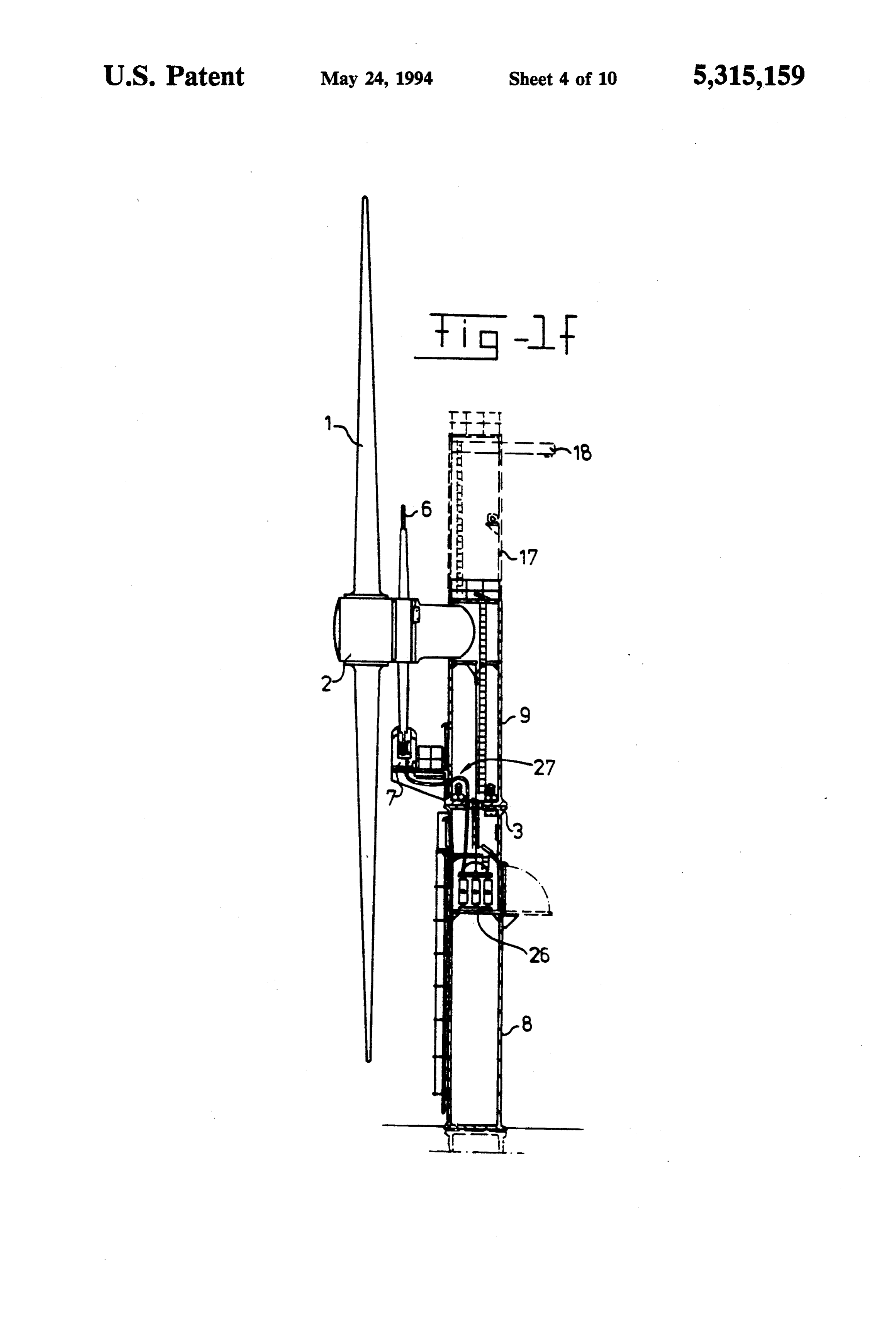
the driven device and the required high speeds, and the FIGS. 1a to 1.fshow examples of embodiments of a supply of such high energies at the above-mentioned wind turbine according to the invention of the horizon high speeds and current intensities by means of current 25 tal shaft type with two stator sectors; supply wire or current collecting rails is a great prob FIGS. 2a to 2d show examples of embodiments of a lem. There is hardly any mention of the use of a linear wind turbine according to the invention of the horizon machine as generator. It is true that a linear generator is tal shaft type with two stator sectors; known from U.S. Pat. No. 4,500,827, but its use is lim FIGS. 3a and 3b show examples of embodiments of a ited solely to a generator of which rotor and stator 30 wind turbine according to the invention of the vertical move linearly along each other. The constant to and fro shaft type with at least two stator sectors; movement means that the efficiency is low, while high FIGS. 4a and 4b show a cross sectional view of a speeds and therefore a high power output are not possi stator sector for use in the wind turbine from FIGS. 1 to ble. 3, and a perspective view of a portion of a stator half, With the generation of electrical energy in the man- 35 respectively; and ner of a generator according to the invention coupled to FIGS. 5a and 5b show a view of a plate stack from a a wind turbine there is no energy loss through reversal stator half of FIG. 4 and of a single plate. of the movement, and very high speeds of the rotor In the examples of embodiments shown in FIG. 1 the relative to the stator are possible. The direct coupling to wind turbine rotor 1 is fixed by means of a shaft 2 on a the turbine rotor also means that there are no conver- 40 turbine mast or tower 8. In the case of this wind turbine sion losses. The efficiency and also the power output of the horizontal shaft type the generator rotor 6, in the are thereby improved. With regard to the use of trac form of a ring, is fitted, for example, near or at the end tion, the problem of the currant take-off does not exist of the rotor blades. In FIG. 1a this ring is fitted at an here either, because the machine winding can be con angle which is generally a right angle relative to the nected directly to the output terminals. 45 plane of the rotor blades or vanes 1. In FIG 1b ring is German Offenlegungsschrift DE-3402035 Al dis fitted as a flat ring, i.e. an open disc, on the end of the closes a wind turbine with a turbine rotor and a genera blades in the same plane thereof. The generator, indi tor equipped with rotor and stator which generator is cated in its entirety by 4, has in addition to the above also a sector machine. The stator in this case comprises mentioned rotor 6 one or more discrete stator sectors one discrete stator sector of which the three-phase cur- 50 each made up of two stator halves 5. These stator halves rent windings, as stated on page 5, can be designed 5 are fixed by means of a U-shaped holder or "cradle' 7 either in a delta connection or in a star connection. This to the rotary or turnable part 9 of the mast 8. A bearing is possible only in the case of a linear machine of the of this turnable part of the mast 8 is indicated by 3. A synchronous type. As is known, a synchronous linear hoisting device integrated in the mast is indicated by 15. machine, just like the ordinary rotationally symmetrical 55 Since in FIGS. 1a and 1b the annular rotor 6 is fixed (synchronous and asynchronous) machine, has in fact a at the end of the turbine rotor 1, this rotor will have a virtually constant air gap induction, as a result of which high peripheral speed or linear passing speed, and one both Y and () connections of the stator windings are discrete stator sector will be sufficient. It is clear that possible. the U-shaped holder 7 of the stator sector(s) with asso In the case of a linear induction machine, such as a 60 ciated stator halves and air gap in the construction is generator with sector-type stator of the asynchronous adapted to the horizontal and vertical position of the type, as in the case of the present application, the mag ring according to FIGS. 1a and 1b. FIG. 1c shows a netic induction in the air gap is built up only gradually, front view of a possible embodiment with a turbine so that the voltages induced in the coils of the stator rotor comprising six blades and a flat ring, i.e. open disc, windings differ greatly from place to place. Added over 65 fitted at the ends of the blades, as generator rotor and a the series-connected poles, the total induced voltages in single discrete stator sector of the generator. the three-phase windings become also unequal. This FIGS. 1d and 1e show yet another embodiment, in asymmetry in the voltages produces not only a system which the annular generator rotor 6 is rigidly coupled
Page 14
to the shaft 2 of the turbine rotor 1 by a rotary disc 10 two stator halves 5. The plate stacks 20, the coil heads of open construction suitable for the purpose. The diam 21 of the coil windings, which windings are taken up in eter of the generator rotor is in this case smaller than the the plate slits 25 and the coil sides 22 are shown in each diameter of the turbine rotor. Here again the peripheral stator half 5. The coil heads are embedded in resin speed of the generator rotor 6 is sufficient to make use 5 (hatched). Reinforcement ribs 23 are fitted on either again of a single stator sector accommodated in a U side of the stator halves 5, and the whole unit is en shaped holder 7. In this example, a hoisting point 11 can closed by an external housing 24. As can be seen from also be used, and a brake can be accommodated in the FIGS. 4a and 4b, the stator is a curved or circular holder 16 lying at the top. segment shape. The plate stack provided in each stator FIG. f shows an example of an embodiment of a 10 wind turbine of the horizontal shaft type with a genera half is in the form of a circular segment, the individual plates of which are also in circular segment form and tor rotor 6 of smaller diameter. In this embodiment the each comprise a single plate provided with slits 25. way in which the shaft stub end of the turbine rotor 1 and of the generator rotor 6 is accommodated and bear andFIG. 5a shows such a plate stack20 in extended form, ing-supported in the top side of the mast can be seen 15 plate stack5b20,
FIG. shows a part of one of the plates from this namely the part whose length corre clearly. Since the gondola for the usual converter, sponds to one pole geared transmission and the like from the state of the art FIG. 5a by the crosspitch, as indicated in each case in sectional planes shown by dotted is now omitted, space has now become available for a lines.
separate tower part 17 with a hoisting unit 18. This hoisting unit, which in the state of the art was virtually 20 For such a wind turbine with a generator as a sector impossible, can be used with particularly great advan machine of the asynchronous type for the generation of tage during the installation of the wind turbine on the andiameteroutput of 550 kW the following data apply: of turbine rotor: 35 m mast and for any subsequent repairs. This means that the shaft height: 40 m use of a hoisting gantry on a special ship or a large hoisting crane is no longer necessary. The turning 25 wind speed: 5-25 m/s output: 550 kW mechanism is again indicated by 3. diameter of generator rotor: 10 m FIG. 1f also shows connections, or leads, 27 which speed of rotation: 40 rp.m.
act as leads of the stator windings. The leads 27 are connected to each stator half in the U-shaped holder 7 Although the above-mentioned turbine is described and a three-phase transformer 30 in its embodiment for a wind application, it goes with FIGS. 2a and 2b show examples of embodiments of a out saying that this turbine can also be used with other wind turbine of the horizontal shaft type in which also forms of motion energy for conversion into electrical compared with FIGS. 1a to 1c the generator rotor 6 has energy. For example, it is conceivable for this turbine to a smaller diameter than the periphery of the turbine be used in water flows.
rotor 1. Since the peripheral speed or linear speed here 35 I claim:
is lower than in the case of the examples of FIG. 1a to 1. A wind turbine for generating electrical energy by 1c, two discrete stator sectors used here in U-shaped means of wind energy, comprising: a turbine rotor holders. If necessary, more sectors can be provided. In mountable on a mast and being rotatable about a rotor FIG. 2a the generator ring 6 is fixed directly to the shaft with one or more rotor blades, and a generator of rotor blades 1. In FIG.2b the flat ring of the generator 40 the asynchronous sector machine type equipped with a rotor 6, again on a separate open disc construction, is generator rotor directly coupled to the turbine rotor in coupled directly to the shaft of the rotor turbine. FIGS. the form of a continuous, uninterrupted annular ring of 2c and 2d show a side view and a front view respec electrically conductive material, and one or more dis tively of a variant of an embodiment of the generator crete stator sectors, the one or more discrete stator rotor 6, which is fixed separately on the shaft 2 of the 45 sectors extending along a portion of the annular genera turbine rotor, again by means of an open disc-type tor rotor on opposite sides thereof.
structure 10. A hoisting point is again indicated by 11. 2. Wind turbine according to claim 1, in which the FIGS. 3a and 3b show two examples of embodiments one or more discrete stator sectors each comprise two of a wind turbine of the vertical shaft type with two or stator halves (5) which are fixed on the legs of a U more associated turbine blades of known form. These 50 shaped holder (7) mounted on the mast (8) and define an blades are fixed to the turbine tube 12. The rotor blades air gap between them, each stator half (5) containing a 1 rotating about the shaft 2 on the mast 8 are firmly plate stack (20) with slits for the coil windings, each fixed at the bottom side to an open, horizontal, jointly individual plate of which is a single plate which is a turning rotor blade supporting structure 14. In FIG.3a circular segment shape, while the annular generator the annular generator rotor is in the form of a flat ring 55 rotor passes continuously into the air gap between the or open disc 6 fitted on a flanged edge 13 on the end of two stator halves of each discrete stator sector (FIG. 4 the rotor blade supporting structure 14. In FIG. 3b this and 5).
annular generator rotor is in the form of a ring project 3. Wind turbine according to claim 2, being of a hori ing vertically downwards. The stator sectors used here zontal shaft type, and the generator rotor (6) forms a extend horizontally in the case of FIG. 3a and vertically 60 ring standing out at right angles to the essentially verti in the case of FIG. 3b. cal plane of the turbine rotor blades (10), and the U FIGS. 4a and 4b show a cross sectional view of a shaped holder (7) of each discrete stator sector grips sector stator and a perspective view of a portion of a round the ring in the essentially horizontal plane. stator half, respectively, in a wind turbine of the hori 4. Wind turbine according to claim 3, in which the zontal shaft type. The spoke-type structure and the 65 annular generator rotor (6) is fitted on or near the end of rotor disc belonging to the wind turbine are indicated in the rotor blades (10).
FIG. 4a by 10 and 6 respectively. The stator accommo 5. Wind turbine according to claim 3 wherein the dated in the U-shaped holder 7 is again made up of the annular generator rotor (6) is fitted on the turbine rotor
Page 15
shaft at a distance from the turbine rotor and has a 8. Wind turbine according to claim 7, in which the diameter smaller than the diameter of the turbine blades. annular generator rotor (6) projects downwards as a 6. Wind turbine according to claim 2, being of a hori ring from the rotor supporting structure, and the U zontal shaft type, and the generator rotor (6) forms a flat shaped holder (7) of each discrete stator sector grips ring extending in the essentially vertical plane, and the 5 round the ring in the vertical plane. U-shaped holder of each discrete stator sector grips 9. Wind turbine according to claim 7, in which the round the flat ring in the essentially vertical plane. annular generator rotor (6) is in the form of a flat ring 7. Wind turbine according to claim 2, being of a verti fitted on a flanged edge of the rotor blade supporting cal shaft type, and the turbine blades are of a shape structure and extending parallel thereto, and the U which is known per se, extending from the top of the O shaped holder (7) of each discrete stator sector grips turbine rotor sideways and downwards, while the ends round the flat ring in the horizontal plane. of the turbine blades are connected by a generally open 10. Wind turbine according to claim 1, wherein the rotor blade supporting structure (14) to the shaft (2) of rotor shaft (2) of the wind turbine is bearing-supported the turbine rotor, and the annular generator (4) rotor is by a shaft stub end in the mast, and a mast part (17) with fixed on or near the periphery of the rotor blade and 15 a hoisting device (18)sk is xprovided
above
the bearing.
supporting structure at the bottom side thereof.
Provenance
- Collection
- Cited prior art
- Original PDF
- patentimages.storage.googleapis.com →
- Filed
- 1990-10-12
- Pages
- 15
- Method
- pdftotext (the PDF's own text layer) + pdftoppm 300dpi page scans
- Source
- Google Patents bibliographic record
- Granted
- 1994-05-24
- Inventors
- Wilhelmus H. J. K. Gribnau; Holec Projects BV
- Transcribed from
- patentimages.storage.googleapis.com →