patent · US5506453
Machine for converting wind energy to electrical energy
9 April 1996
Page 1 — bibliographic record
IIIHIII III IIII
United States Patent (19) 11 Patent Number: 5,506,453 McCombs 45) Date of Patent: Apr. 9, 1996
54 MACHINE FOR CONVERTING WIND Primary Examiner-Steven L. Stephan ENERGY TO ELECTRICAL ENERGY Assistant Examiner-Christopher Cuneo 76) Inventor: John C. McCombs, 1215 Clearview
Dr., Port Charlotte, Fla. 33953 57 ABSTRACT (21) Appl. No.: 809,965 A machine for converting wind energy into electrical energy (22 Filed: Dec. 18, 1991 comprising in combination a housing; propellers at the forward and rearward ends of the housing mounted on shafts
Related U.S. Application Data for rotation upon a common horizontal axis of rotation; post 63 Continuation-in-part of Ser. No. 477,537, Feb. 9, 1990, means supporting a central extent of the housing for rotation abandoned. in a horizontal plane to face into the wind; an alternator (51) Int. Cl. ........................... H02P 9/04; FO3B 13/00; within the housing formed of a power take off member FO3D 9/00 coupled to one shaft and a rotor coupled to another shaft for 52 U.S. Cl. .................................. 290/44; 290/54; 290/55 counter rotating when the propellers rotate for thereby (58) Field of Search .......................................... 290/44, 55 generating electricity; centrifugal pitch control mechanisms 56 References Cited for varying the pitch of the propellers as a function of the
propeller speed; transmission mechanisms for varying the speed of rotation of the rotor and power take off member as 1,533,467 4/1925 Sargent ..................................... 290/55 a function of the wind speed; brake mechanisms for pro 2,153,523 4/1939 Roberts et al. ........................... 290/55 2,237,857 4/1941 Winderl ... portionately restraining the propellers against rotation; and 2,358,781 9/1944 Albers ..... an aerogovernor operatively coupled with the brake mecha 4,039,848 8/1977 Winderl nisms for control thereof in response to the speed of the wind 4,213,057 7/1980 Are............................................
as determined by the aerogovernor.
OTHER PUBLICATIONS
G. W. Koeppl, "Putnam's Power from the Wind," 1982, pp.
“Alternator Secrets,” Lindsay Publications, Inc., 1977. 5 Claims, 6 Drawing Sheets
Page 2
Drawing sheet — no readable text.
Page 3
Drawing sheet — no readable text.
Page 4
Drawing sheet — no readable text.
Page 5
Drawing sheet — no readable text.
Page 6
Drawing sheet — no readable text.
Page 7
Drawing sheet — no readable text.
Page 8
MACHINE FOR CONVERTING WIND converting wind energy to electrical energy. Such efforts are ENERGY TO ELECTRICAL ENERGY being made to render such devices more efficient, reliable, inexpensive and convenient to use. None of these previous
This is a continuation-in-part of application Ser. No. efforts, however, provides the benefits attendant with the 07/477,537 filed Feb. 9, 1990, now abandoned. 5 present invention. Additionally, the prior patent and com mercial devices and techniques do not suggest the present
BACKGROUND OF THE INVENTION inventive combination of component elements arranged and configured as disclosed and claimed herein.
SUMMARY OF THE INVENTION The present invention achieves its intended purposes, 10 objects and advantages through a new, useful and unobvious
This invention relates to a machine for converting wind energy to electrical energy and, more particularly, to a combination minimum of component elements, with the use of a number of functioning parts, at a reasonable cost machine with two wind driven propellers for counter rotat to manufacture, and by employing only readily available ing the rotor and power generator housing of an alternator. materials.
DESCRIPTION OF THE BACKGROUND ART Therefore, it is an object of this invention to provide an improved machine for converting wind energy into electrical
Electrical power is presently produced through various energy comprising in combination a housing; propellers at techniques. The most common technique is the combustion the forward and rearward ends of the housing mounted on of fossil fuels, such as coal and oil, to create steam which 20 shafts for rotation upon a common horizontal axis of rota turns turbines for driving electric generators or dynamos. tion; post means supporting a central extent of the housing The products of combustion of fossil fuels, however, are for rotation in a horizontal plane to face into the wind; an pollutants. Such pollutants are now concentrated in the air of alternator within the housing formed of a power generator our major cities and are diffusing throughout the air of our housing coupled to one of the shafts and a rotor coupled to planet. Such pollutants include poisons such as sulfates, 25 another shaft for counter rotating when the propellers rotate nitrates, carbon oxides, etc. Electric power is also produced for thereby generating electricity; centrifugal pitch control by atomic plants. Such plants, however, generate nuclear mechanisms for varying the pitch of the propellers as a waste which is inherently dangerous and, in addition, function of the wind speed; transmission mechanism for present a serious storage problem. This leaves hydroelectric, varying the speed of rotation of the rotor and power gen solar, geothermal, tidal, and wind as alternate energy sources 30 erator housing as a function of the wind speed; brake which are environmentally clean and not inherently danger mechanisms for proportionately restraining the propellers OS. against rotation; and an aerogovernor operatively coupled One alternate energy source which is particularly prom with the brake mechanisms for control thereof in response to ising are wind farms which are presently in use but only on the speed of the wind as determined by the aerogovernor. a limited basis. Known windmills are generally very large 35 It is a further object of this invention to convert wind and expensive. Smaller relatively inexpensive units if of energy to electrical energy by counter rotating blades of a advanced, more efficient, designs could provide more energy wind driven machine to thereby counter rotate the rotor and per land area, especially if utilized on a national or world the power generator housing of an alternator. wide scale. Such units could be utilized individually or It is a further object of the present invention to more connected to existing utility power grids, whether atomic or 40 efficiently utilize the rotating blades of a wind conversion fossil. machine in producing electricity. Various techniques are employed commercially or are Lastly, it is an object of the invention to automatically disclosed in the patent literature for converting wind energy control the operating parameters of a wind conversion to electrical energy. Note, for example, U.S. Pat. Nos. machine as a function of the wind speed. 4,066,911 to Sarchet; 4,171,491 to Theyse; 4,186.312 to 45 The foregoing has outlined some of the more pertinent Dvorak; 4,291,233 to Kirschbaum; 4,291,235 to Bergey; objects of this invention. These objects should be construed 4,316,096 to Syverson; 4,357,542 to Kirschbaum; 4,435,646 to be merely illustrative of some of the more prominent to Coleman; 4,446,376 to Baker; 4,461,957 to Jallen; 4,447, features and applications of the present invention. Many 738 to Allison; 4,535,252 to Jacobs; 4,565,929 to Baskin; other beneficial results can be attained by applying the 4,673,822 to Kikuchi; 4,695,736 to Doman; and 4,703,189 50 disclosed invention in a different manner or by modifying to DiValentin. All of these patents convert wind energy to the invention within the scope of the disclosure. Accord electrical energy by a single propeller with blades rotatable ingly, other objects and a fuller understanding of the inven in a plane around a horizontal axis. All are of marginal tion may be had by referring to the summary of the invention efficiency since they utilize a dynamo or generator with a and the detailed description of the preferred embodiment in fixed power take off member and a rotatable rotor for 55 addition to the scope of the invention defined by the claims converting wind power to direct current electrical power. taken in conjunction with the accompanying drawings. Note is also taken of U.S. Pat. No. 4,449,053 to Kutcher.
Kutcher is similar to the above listed patents but utilizes a SUMMARY OF THE INVENTION vertical axis about which its propeller rotates. Lastly, U.S.
Pat. Nos. 4,213,057 to Are and 4,345,161 to Crompton 60 The invention is defined by the appended claims with the disclose two sets of blades counter rotating about a hori specific embodiment shown in the attached drawings. For zontal axis for rotating both a rotor and stator. The rotor and the purpose of summarizing the invention, the invention stator constitute a dynamo or generator for converting wind may be incorporated into an improved machine for convert energy to direct current electrical energy. ing wind energy into electrical energy comprising in com As illustrated by the great number of prior patents as well 65 bination a housing; propellers at the forward and rearward as commercial devices and techniques, efforts are continu ends of the housing mounted on shafts for rotation upon a ously being made in an attempt to improve devices for common horizontal axis of rotation; post means supporting
Page 9
a central extent of the housing for rotation in a horizontal carrying out the same purposes of the present invention, it plane to face into the wind; an alternator within the housing should be realized by those skilled in the art that such formed of a power generator housing coupled to one of the equivalent structures do not depart from the spirit and scope shafts and a rotor coupled to another shaft for counter of the invention as set forth in the appended claims. rotating when the propellers rotate for thereby generating electricity; centrifugal pitch control mechanisms for varying BRIEF DESCRIPTION OF THE DRAWINGS the pitch of the propellers as a function of the propeller speed; transmission mechanisms for varying the speed of For a fuller understanding of the nature and objects of the rotation of the rotor and power generator housing as a present invention, reference should be had to the following function of the wind speed; brake mechanisms for propor tionately restraining the propellers against over rotation; and O detailed panying description taken in conjunction with the accom drawings in which:
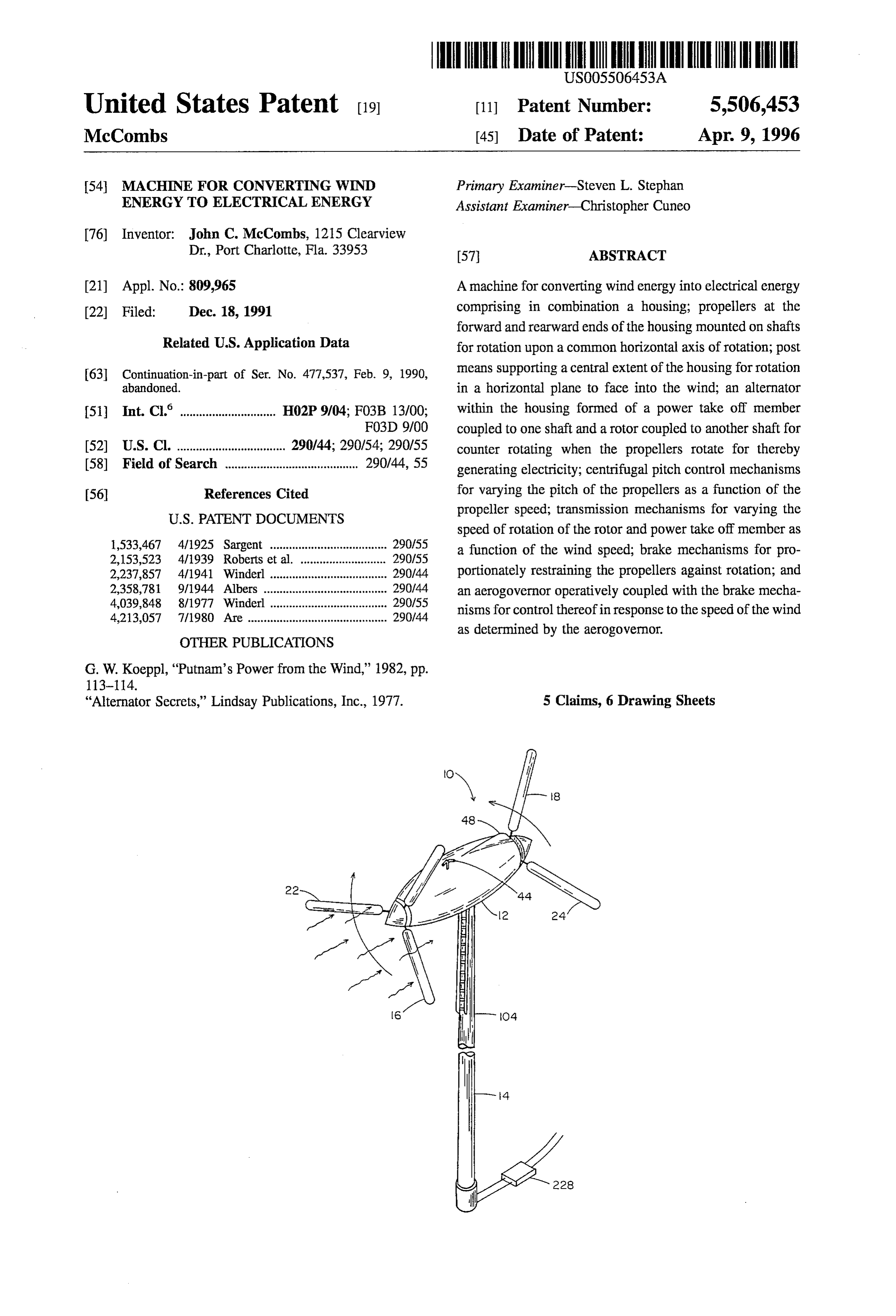
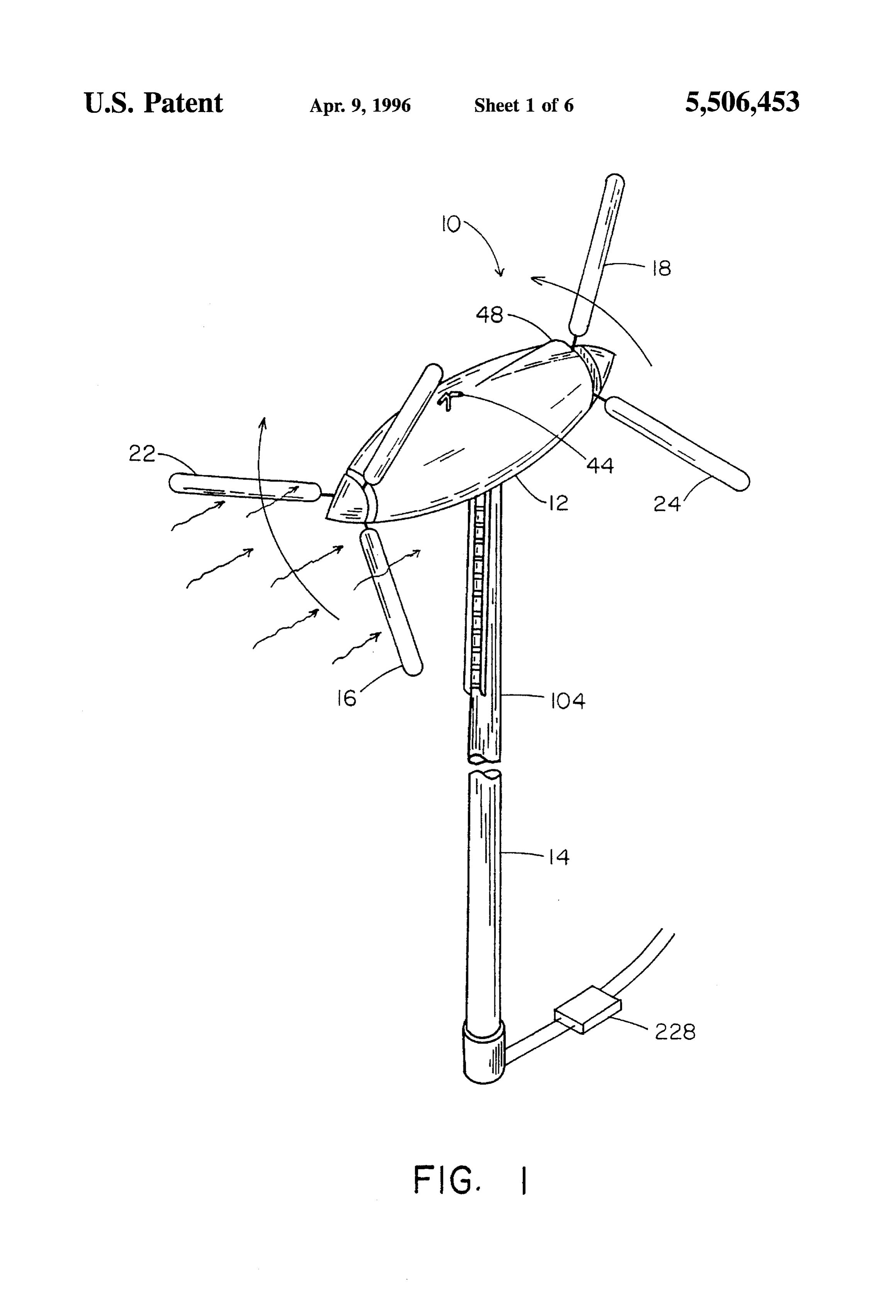
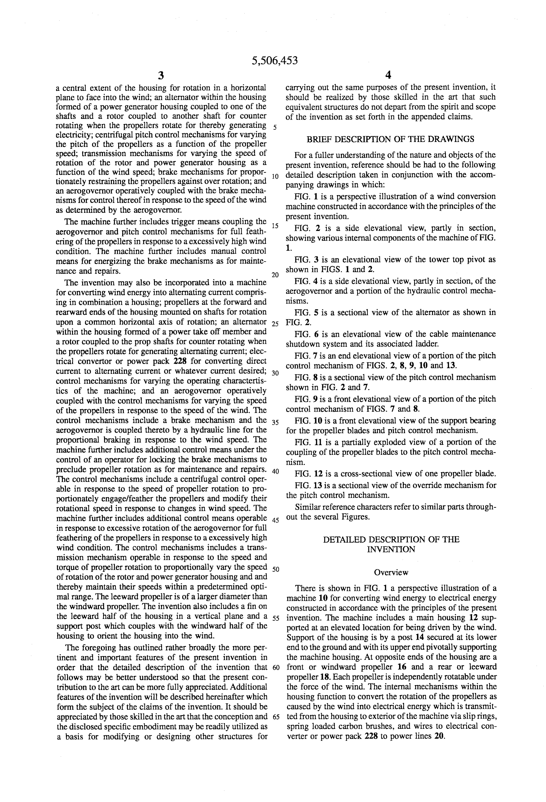
an aerogovernor operatively coupled with the brake mecha nisms for control thereof in response to the speed of the wind FIG. 1 is a perspective illustration of a wind conversion as determined by the aerogovernor. machine constructed in accordance with the principles of the The machine further includes trigger means coupling the 15 present invention.
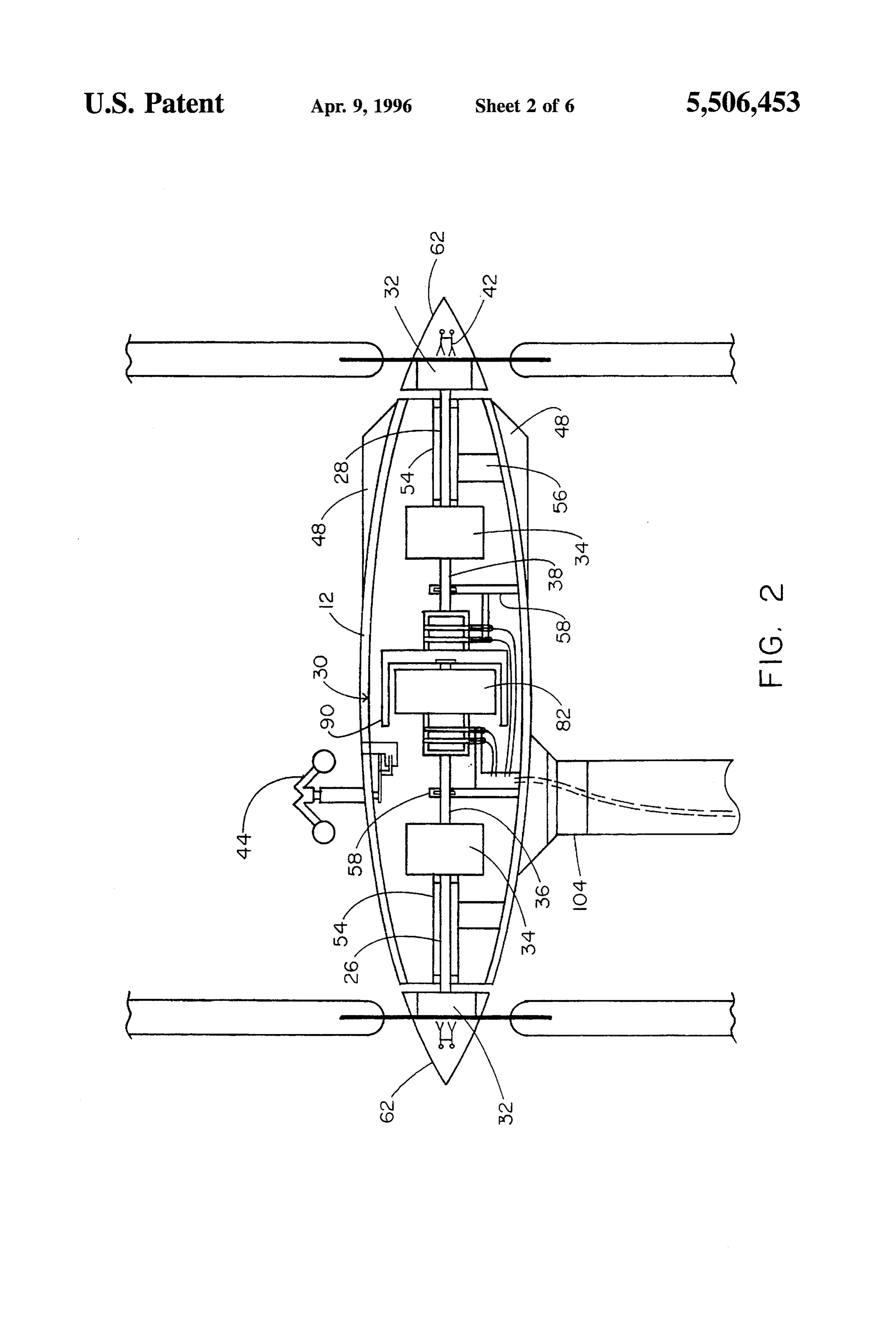
aerogovernor and pitch control mechanisms for full feath FIG. 2 is a side elevational view, partly in section, ering of the propellers in response to a excessively high wind showing various internal components of the machine of FIG. condition. The machine further includes manual control 1.
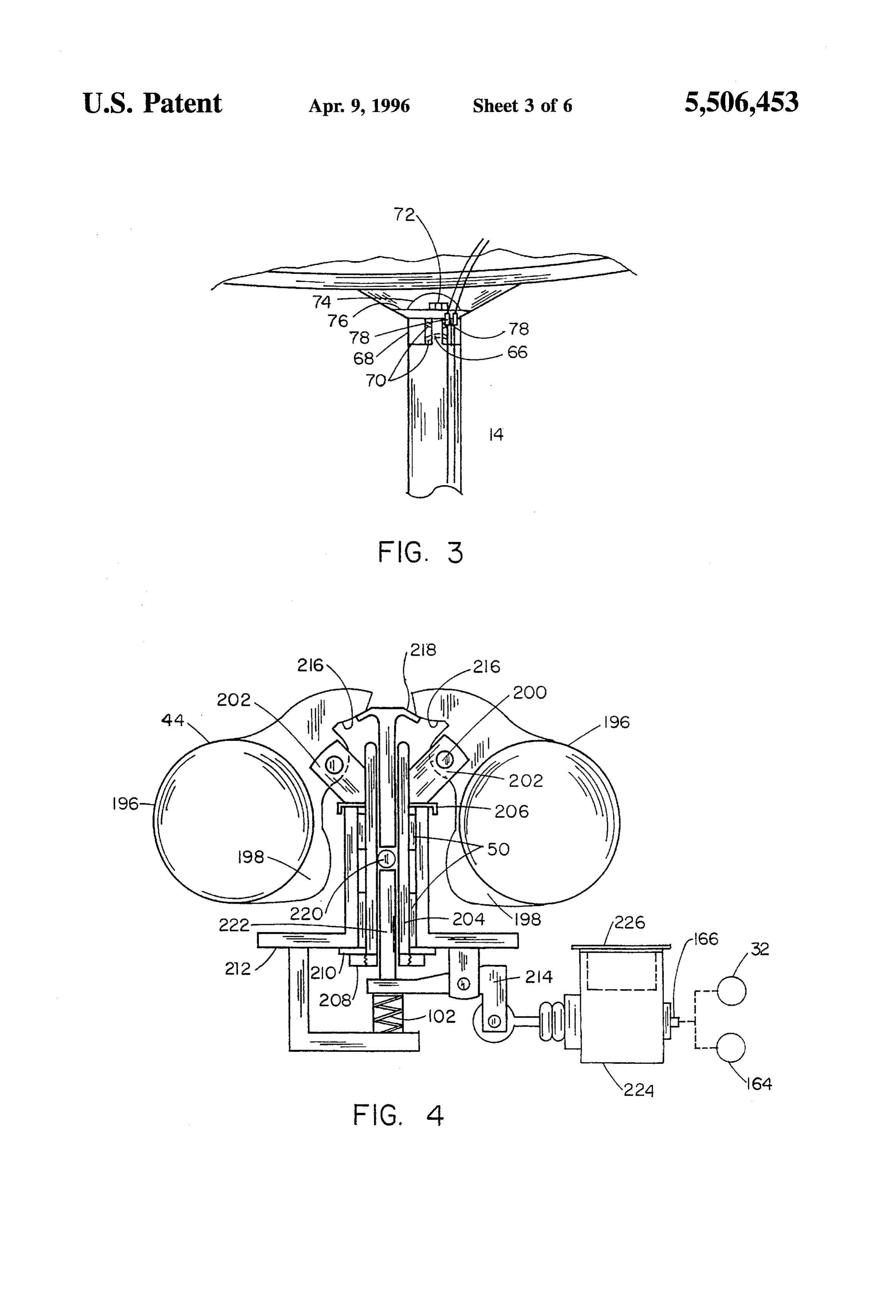
means for energizing the brake mechanisms as for mainte FIG. 3 is an elevational view of the tower top pivot as nance and repairs. 20 shown in FIGS. 1 and 2.
The invention may also be incorporated into a machine FIG. 4 is a side elevational view, partly in section, of the for converting wind energy into alternating current compris aerogovernor and a portion of the hydraulic control mecha ing in combination a housing; propellers at the forward and nisms.
rearward ends of the housing mounted on shafts for rotation FIG. 5 is a sectional view of the alternator as shown in upon a common horizontal axis of rotation; an alternator 25 FIG. 2.
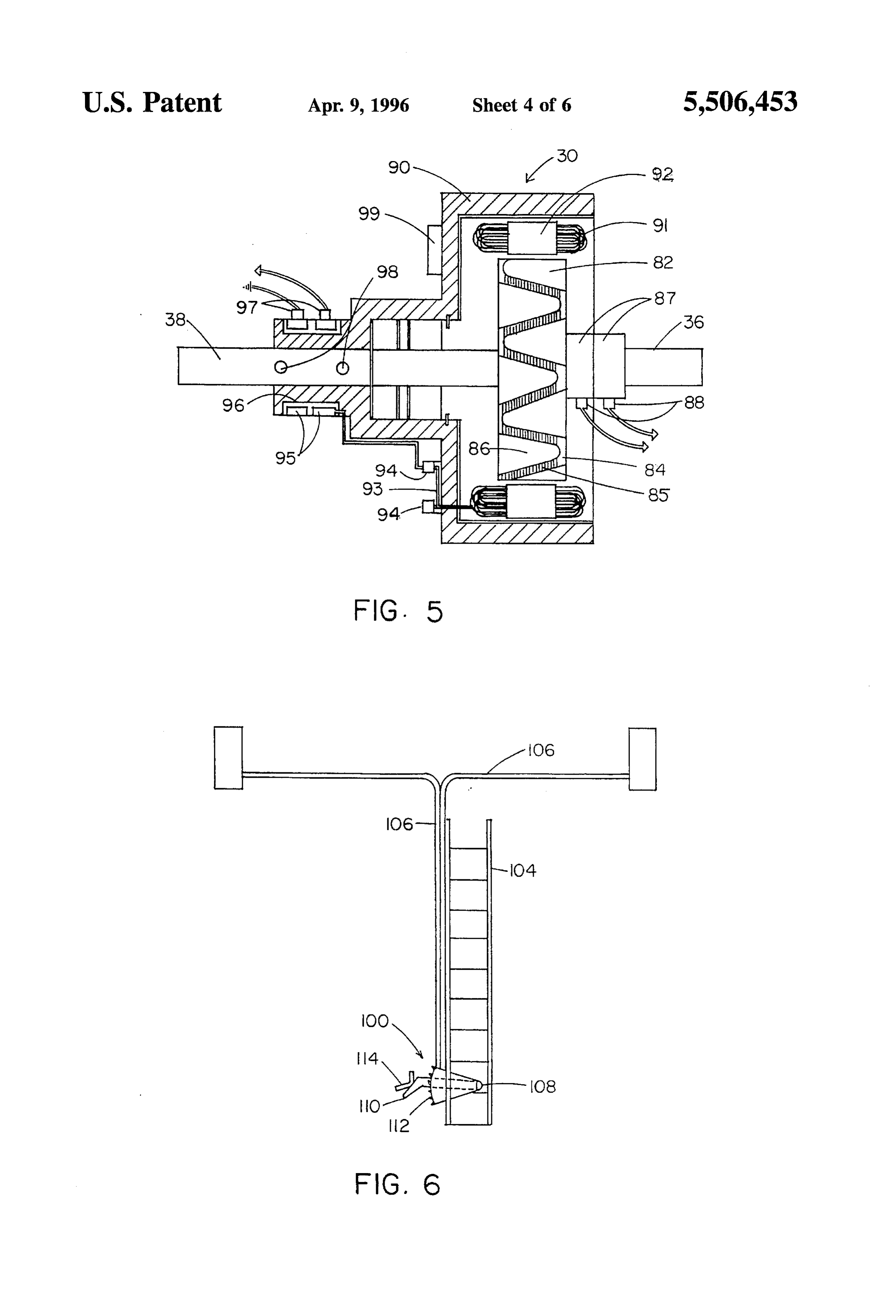
within the housing formed of a power take off member and FIG. 6 is an elevational view of the cable maintenance a rotor coupled to the prop shafts for counter rotating when shutdown system and its associated ladder. the propellers rotate for generating alternating current; elec FIG. 7 is an end elevational view of a portion of the pitch trical convertor or power pack 228 for converting direct current to alternating current or whatever current desired; 30 FIG. 8mechanism control
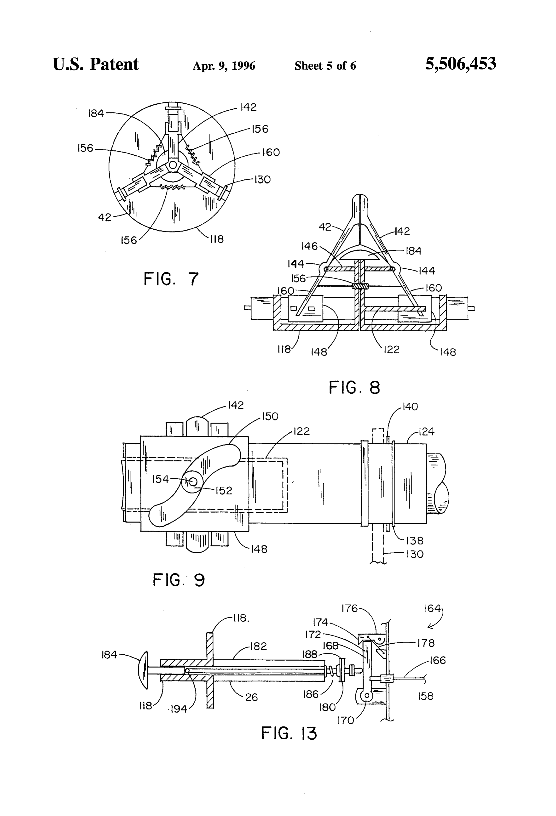
sectional view of the pitch control mechanism control mechanisms for varying the operating charactertis shown in FIG. 2 and 7.
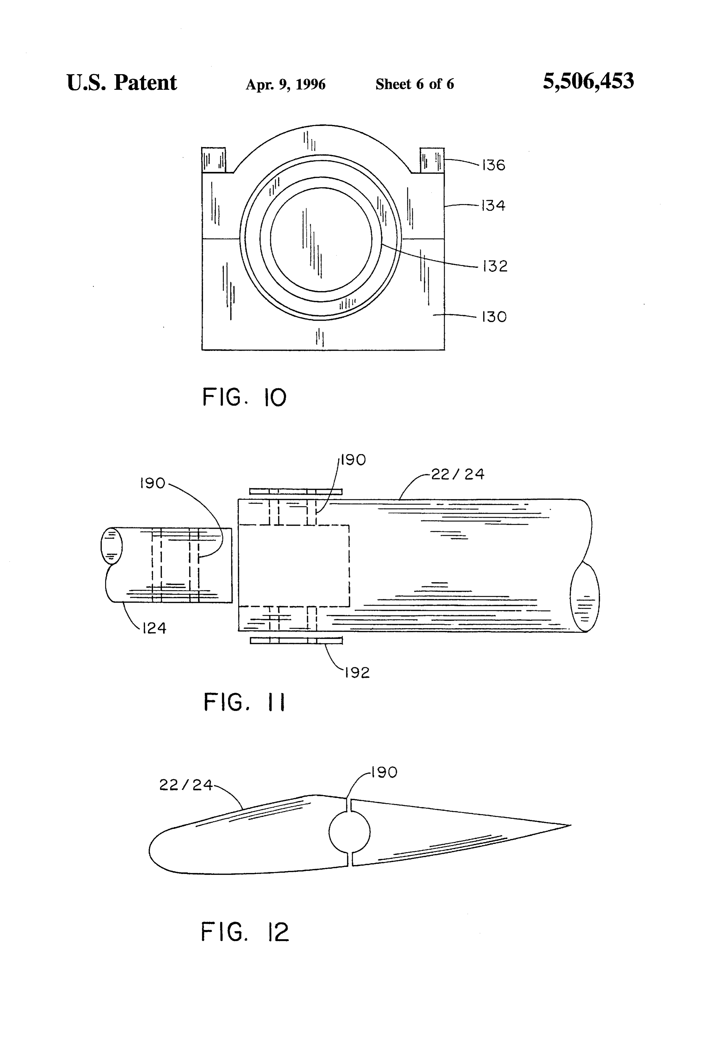
tics of the machine; and an aerogovernor operatively coupled with the control mechanisms for varying the speed FIG. 9 is a front elevational view of a portion of the pitch of the propellers in response to the speed of the wind. The control mechanism of FIGS. 7 and 8. control mechanisms include a brake mechanism and the 35 FIG. 10 is a front elevational view of the support bearing aerogovernor is coupled thereto by a hydraulic line for the for the propeller blades and pitch control mechanism. proportional braking in response to the wind speed. The FIG. 11 is a partially exploded view of a portion of the machine further includes additional control means under the coupling of the propeller blades to the pitch control mecha control of an operator for locking the brake mechanisms to nism.
preclude propeller rotation as for maintenance and repairs. 40 FIG. 12 is a cross-sectional view of one propeller blade. The control mechanisms include a centrifugal control oper FIG. 13 is a sectional view of the override mechanism for able in response to the speed of propeller rotation to pro portionately engage/feather the propellers and modify their the pitch control mechanism.
rotational speed in response to changes in wind speed. The Similar reference characters refer to similar parts through machine further includes additional control means operable 45 out the several Figures.
in response to excessive rotation of the aerogovernor for full feathering of the propellers in response to a excessively high DETAILED DESCRIPTION OF THE wind condition. The control mechanisms includes a trans INVENTION mission mechanism operable in response to the speed and torque of propeller rotation to proportionally vary the speed 50 Overview of rotation of the rotor and power generator housing and and thereby maintain their speeds within a predetermined opti There is shown in FIG. 1 a perspective illustration of a mal range. The leeward propeller is of a larger diameter than machine 10 for converting wind energy to electrical energy the windward propeller. The invention also includes a fin on constructed in accordance with the principles of the present the leeward half of the housing in a vertical plane and a 55 invention. The machine includes a main housing 12 Sup support post which couples with the windward half of the ported at an elevated location for being driven by the wind. housing to orient the housing into the wind. Support of the housing is by a post 14 secured at its lower The foregoing has outlined rather broadly the more per end to the ground and with its upper end pivotally supporting tinent and important features of the present invention in the machine housing. At opposite ends of the housing are a order that the detailed description of the invention that 60 front or windward propeller 16 and a rear or leeward follows may be better understood so that the present con propeller 18. Each propeller is independently rotatable under tribution to the art can be more fully appreciated. Additional the force of the wind. The internal mechanisms within the features of the invention will be described hereinafter which housing function to convert the rotation of the propellers as form the subject of the claims of the invention. It should be caused by the wind into electrical energy which is transmit appreciated by those skilled in the art that the conception and 65 ted from the housing to exterior of the machine via slip rings, the disclosed specific embodiment may be readily utilized as spring loaded carbon brushes, and wires to electrical con a basis for modifying or designing other structures for verter or power pack 228 to power lines 20.
Page 10
Each propeller is formed of one or more blades 22 and 24. extend upwardly from the bottom of the housing with In the preferred embodiment as shown, three such blades are bearings at their upper ends for rotationally Supporting the utilized for each propeller. The blades are equally spaced at electrical shafts and alternator 30. The rotor 82 and power 120 degrees around a common axis extending essentially generator housing 90 are at the axial interior ends of the horizontally through the horizontal center of the housing. electrical shafts 36 and 38. Also centrally disposed along the Any number of equally spaced blades could be readily axis are the braking mechanisms 32 at the axially exterior utilized as a function of the particular application. In addi ends of the prop shafts 26 and 28. tion, the front blades 22 in this embodiment are about 5 feet At the axially exterior ends of the housing are rotatable in length, the rear blades 24 are about 20 percent larger, spinners 62 mounted for rotation with the propeller and the about 6 feet in length so as to be more positively driven by 10 shafts 26 and 28. Within the spinners 62 are the propeller the wind and to assistin proper directional orientation of the blade pitch control mechanisms 42. These mechanisms and housing. Such lengths are also a function of the particular their mode of operation are disclosed in greater detail application. hereinafter.
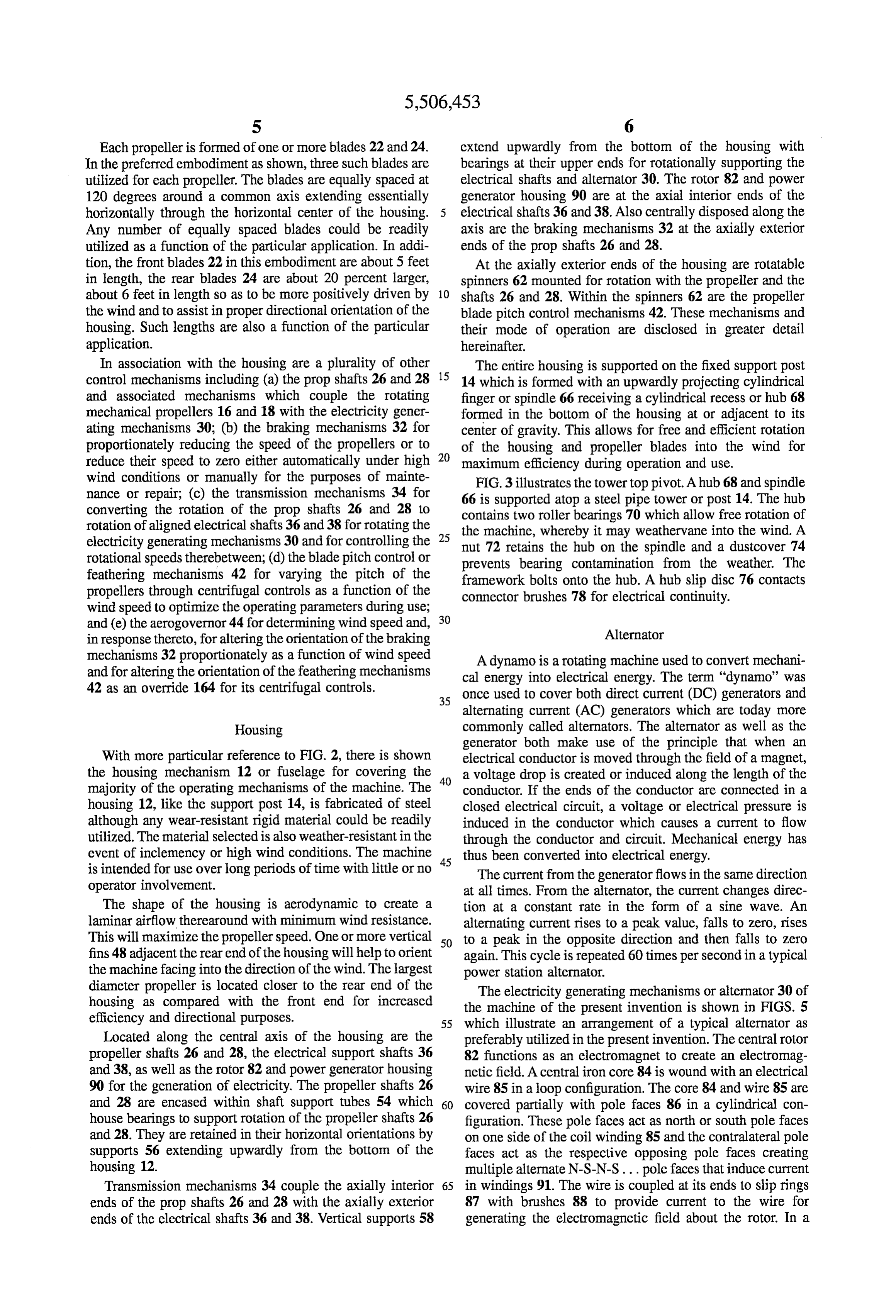
In association with the housing are a plurality of other The entire housing is supported on the fixed support post control mechanisms including (a) the prop shafts 26 and 28 15 14 which is formed with an upwardly projecting cylindrical and associated mechanisms which couple the rotating finger or spindle 66 receiving a cylindrical recess or hub 68 mechanical propellers 16 and 18 with the electricity gener formed in the bottom of the housing at or adjacent to its ating mechanisms 30; (b) the braking mechanisms 32 for center of gravity. This allows for free and efficient rotation proportionately reducing the speed of the propellers or to of the housing and propeller blades into the wind for reduce their speed to zero either automatically under high 20 maximum efficiency during operation and use. wind conditions or manually for the purposes of mainte FIG.3 illustrates the tower top pivot. A hub 68 and spindle nance or repair; (c) the transmission mechanisms 34 for 66 is supported atop a steel pipe tower or post 14. The hub converting the rotation of the prop shafts 26 and 28 to contains two roller bearings 70 which allow free rotation of rotation of aligned electrical shafts 36 and 38 for rotating the 25 the electricity generating mechanisms 30 and for controlling the nut machine, whereby it may weathervane into the wind. A 72 retains the hub on the spindle and a dustcover 74 rotational speeds therebetween; (d) the blade pitch control or prevents bearing contamination from the weather. The feathering mechanisms 42 for varying the pitch of the framework bolts onto the hub. A hub slip disc 76 contacts propellers through centrifugal controls as a function of the connector brushes 78 for electrical continuity. wind speed to optimize the operating parameters during use;
and (e) the aerogovernor 44 for determining wind speed and, 30 in response thereto, for altering the orientation of the braking Alternator mechanisms 32 proportionately as a function of wind speed A dynamo is a rotating machine used to convert mechani and for altering the orientation of the feathering mechanisms cal energy into electrical energy. The term "dynamo' was 42 as an override 164 for its centrifugal controls.
35 once used to cover both direct current (DC) generators and alternating current (AC) generators which are today more
Housing commonly called alternators. The alternator as well as the generator both make use of the principle that when an
With more particular reference to FIG. 2, there is shown electrical conductor is moved through the field of a magnet, the housing mechanism 12 or fuselage for covering the 40 a voltage drop is created or induced along the length of the majority of the operating mechanisms of the machine. The conductor. If the ends of the conductor are connected in a housing 12, like the support post 14, is fabricated of steel closed electrical circuit, a voltage or electrical pressure is although any wear-resistant rigid material could be readily induced in the conductor which causes a current to flow utilized. The material selected is also weather-resistant in the through the conductor and circuit. Mechanical energy has event of inclemency or high wind conditions. The machine 45 thus been converted into electrical energy. is intended for use over long periods of time with little or no The current from the generator flows in the same direction operator involvement. at all times. From the alternator, the current changes direc The shape of the housing is aerodynamic to create a tion at a constant rate in the form of a sine wave. An laminar airflow therearound with minimum wind resistance. alternating current rises to a peak value, falls to zero, rises This will maximize the propeller speed. One or more vertical 50 to a peak in the opposite direction and then falls to Zero fins 48 adjacent the rear end of the housing will help to orient again. This cycle is repeated 60 times per second in a typical the machine facing into the direction of the wind. The largest power station alternator.
diameter propeller is located closer to the rear end of the housing as compared with the front end for increased theThe electricity generating mechanisms or alternator 30 of machine of the present invention is shown in FIGS. 5 efficiency and directional purposes. 55 which illustrate an arrangement of a typical alternator as Located along the central axis of the housing are the preferably utilized in the present invention. The central rotor propeller shafts 26 and 28, the electrical support shafts 36 82 functions as an electromagnet to create an electromag and 38, as well as the rotor 82 and power generator housing netic field. A central iron core 84 is wound with an electrical 90 for the generation of electricity. The propeller shafts 26 wire 85 in a loop configuration. The core 84 and wire 85 are and 28 are encased within shaft support tubes 54 which 60 covered partially with pole faces 86 in a cylindrical con house bearings to support rotation of the propeller shafts 26 figuration. These pole faces act as north or south pole faces and 28. They are retained in their horizontal orientations by on one side of the coil winding 85 and the contralateral pole supports 56 extending upwardly from the bottom of the faces act as the respective opposing pole faces creating housing 12. multiple alternate N-S-N-S... pole faces that induce current Transmission mechanisms 34 couple the axially interior 65 in windings 91. The wire is coupled at its ends to slip rings ends of the prop shafts 26 and 28 with the axially exterior 87 with brushes 88 to provide current to the wire for ends of the electrical shafts 36 and 38. Vertical supports 58 generating the electromagnetic field about the rotor. In a
Page 11
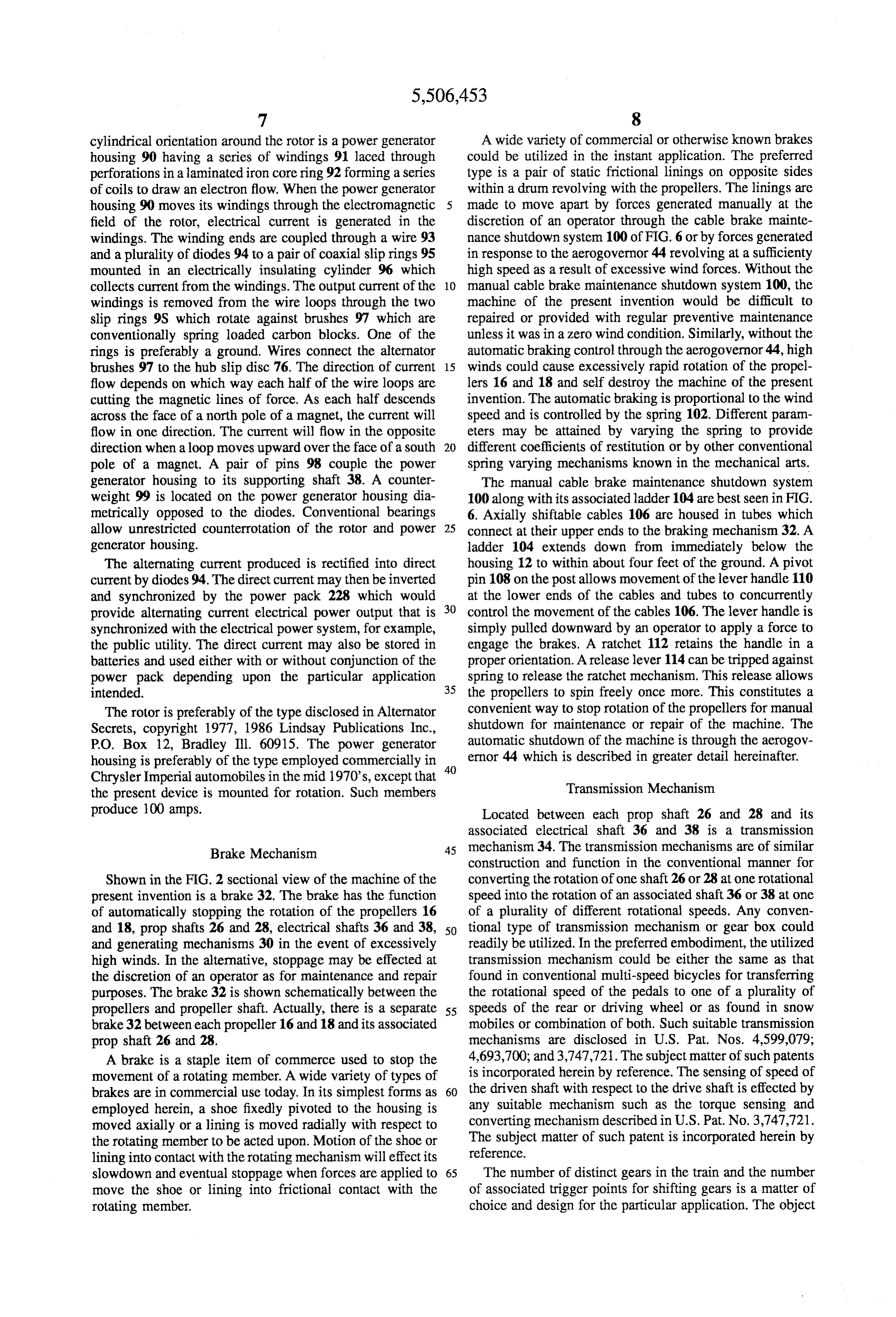
cylindrical orientation around the rotor is a power generator A wide variety of commercial or otherwise known brakes housing 90 having a series of windings 91 laced through could be utilized in the instant application. The preferred perforations in a laminated iron core ring 92 forming a series type is a pair of static frictional linings on opposite sides of coils to draw an electron flow. When the power generator within a drum revolving with the propellers. The linings are housing 90 moves its windings through the electromagnetic made to move apart by forces generated manually at the field of the rotor, electrical current is generated in the discretion of an operator through the cable brake mainte windings. The winding ends are coupled through a wire 93 nance shutdown system 100 of FIG. 6 or by forces generated and a plurality of diodes 94 to a pair of coaxial slip rings 95 in response to the aerogovernor 44 revolving at a sufficienty mounted in an electrically insulating cylinder 96 which high speed as a result of excessive wind forces. Without the collects current from the windings. The output current of the 10 manual cable brake maintenance shutdown system 100, the windings is removed from the wire loops through the two machine of the present invention would be difficult to slip rings 9S which rotate against brushes 97 which are repaired or provided with regular preventive maintenance conventionally spring loaded carbon blocks. One of the unless it was in a zero wind condition. Similarly, without the rings is preferably a ground. Wires connect the alternator automatic braking control through the aerogovernor 44, high brushes 97 to the hub slip disc 76. The direction of current 15 winds could cause excessively rapid rotation of the propel flow depends on which way each half of the wire loops are lers 16 and 18 and self destroy the machine of the present cutting the magnetic lines of force. As each half descends invention. The automatic braking is proportional to the wind across the face of a north pole of a magnet, the current will speed and is controlled by the spring 102. Different param flow in one direction. The current will flow in the opposite eters may be attained by varying the spring to provide direction when a loop moves upward over the face of a south 20 different coefficients of restitution or by other conventional pole of a magnet. A pair of pins 98 couple the power spring varying mechanisms known in the mechanical arts. generator housing to its supporting shaft 38. A counter The manual cable brake maintenance shutdown system weight 99 is located on the power generator housing dia 100 along with its associated ladder 104 are best seen in FIG. metrically opposed to the diodes. Conventional bearings 6. Axially shiftable cables 106 are housed in tubes which allow unrestricted counterrotation of the rotor and power 25 connect at their upper ends to the braking mechanism 32. A generator housing. ladder 104 extends down from immediately below the The alternating current produced is rectified into direct housing 12 to within about four feet of the ground. A pivot current by diodes 94. The direct current may then be inverted pin 108 on the postallows movement of the lever handle 110 and synchronized by the power pack 228 which would at the lower ends of the cables and tubes to concurrently provide alternating current electrical power output that is 30 control the movement of the cables 106. The lever handle is synchronized with the electrical power system, for example, simply pulled downward by an operator to apply a force to the public utility. The direct current may also be stored in engage the brakes. A ratchet 112 retains the handle in a batteries and used either with or without conjunction of the proper orientation. A release lever 114 can be tripped against power pack depending upon the particular application spring to release the ratchet mechanism. This release allows intended. 35 the propellers to spin freely once more. This constitutes a The rotor is preferably of the type disclosed in Alternator convenient way to stop rotation of the propellers for manual Secrets, copyright 1977, 1986 Lindsay Publications Inc., shutdown for maintenance or repair of the machine. The P.O. Box 12, Bradley Ill. 60915. The power generator automatic shutdown of the machine is through the aerogov housing is preferably of the type employed commercially in 40 ernor 44 which is described in greater detail hereinafter. Chrysler Imperial automobiles in the mid 1970's, except that Transmission Mechanism the present device is mounted for rotation. Such members produce 100 amps. Located between each prop shaft 26 and 28 and its associated electrical shaft 36 and 38 is a transmission
Brake Mechanism 45 mechanism 34. The transmission mechanisms are of similar construction and function in the conventional manner for
Shown in the FIG. 2 sectional view of the machine of the converting the rotation of one shaft 26 or 28 at one rotational present invention is a brake 32. The brake has the function speed into the rotation of an associated shaft 36 or 38 at one of automatically stopping the rotation of the propellers 16 of a plurality of different rotational speeds. Any conven and 18, prop shafts 26 and 28, electrical shafts 36 and 38, 50 tional type of transmission mechanism or gear box could and generating mechanisms 30 in the event of excessively readily be utilized. In the preferred embodiment, the utilized high winds. In the alternative, stoppage may be effected at transmission mechanism could be either the same as that the discretion of an operator as for maintenance and repair found in conventional multi-speed bicycles for transferring purposes. The brake 32 is shown schematically between the the rotational speed of the pedals to one of a plurality of propellers and propeller shaft. Actually, there is a separate 55 speeds of the rear or driving wheel or as found in snow brake 32 between each propeller 16 and 18 and its associated mobiles or combination of both. Such suitable transmission prop shaft 26 and 28. mechanisms are disclosed in U.S. Pat. Nos. 4,599,079; A brake is a staple item of commerce used to stop the 4,693,700; and 3,747,721. The subject matter of such patents movement of a rotating member. A wide variety of types of is incorporated herein by reference. The sensing of speed of brakes are in commercial use today. In its simplest forms as 60 the driven shaft with respect to the drive shaft is effected by employed herein, a shoe fixedly pivoted to the housing is any suitable mechanism such as the torque sensing and moved axially or a lining is moved radially with respect to converting mechanism described in U.S. Pat. No. 3,747,721. the rotating member to be acted upon. Motion of the shoe or The subject matter of such patent is incorporated herein by reference.
lining into contact with the rotating mechanism will effect its slowdown and eventual stoppage when forces are applied to 65 The number of distinct gears in the train and the number move the shoe or lining into frictional contact with the of associated trigger points for shifting gears is a matter of rotating member. choice and design for the particular application. The object
Page 12
of the selection of the transmission, torque sensor and pressure acting against the central portion of a lever 168. The converter as well as the trigger points is to drive the power lever rests against a push rod 182 which extends through generator housing and rotor within a preselected range of both the hollow prop shaft 26 and 28 and the hollow pitch rotational speeds for maximum efficiency. control mechanism framework 118 central axis. The lever is pivoted at a first end 170. The opposite end 172 is con strained from movement by a tab 174 at the upper end of a
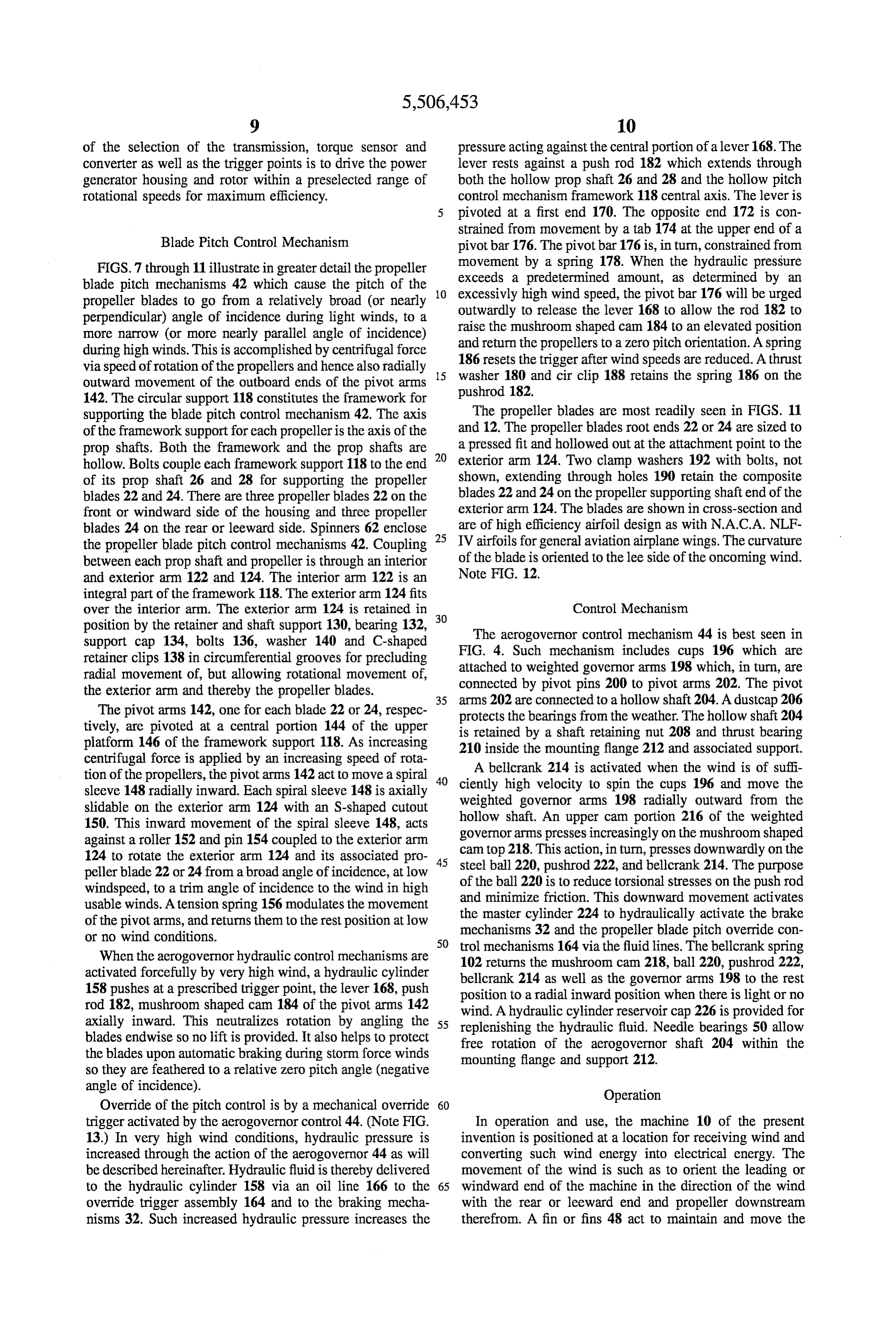
Blade Pitch Control Mechanism pivot bar 176. The pivot bar 176 is, in turn, constrained from FIGS. 7through 11 illustrate in greater detail the propeller movement by a spring 178. When the hydraulic pressure blade pitch mechanisms 42 which cause the pitch of the exceeds a predetermined amount, as determined by an propeller blades to go from a relatively broad (or nearly 10 excessivly outwardly high wind speed, the pivot bar 176 will be urged to release the lever 168 to allow the rod 182 to perpendicular) angle of incidence during light winds, to a more narrow (or more nearly parallel angle of incidence) raise the mushroom shaped cam 184 to an elevated position during high winds. This is accomplished by centrifugal force and return the propellers to a Zero pitch orientation. A spring 186 resets the trigger after windspeeds are reduced. A thrust via speed of rotation of the propellers and hence also radially 15 washer outward movement of the outboard ends of the pivot arms 180 and circlip 188 retains the spring 186 on the 142. The circular support 118 constitutes the framework for pushrod 182.
supporting the blade pitch control mechanism 42. The axis The propeller blades are most readily seen in FIGS. 11 of the framework support for each propeller is the axis of the and 12. The propeller blades root ends 22 or 24 are sized to prop shafts. Both the framework and the prop shafts are 20 a pressed fit and hollowed out at the attachment point to the hollow. Bolts couple each framework support 118 to the end exterior arm 124. Two clamp washers 192 with bolts, not of its prop shaft 26 and 28 for supporting the propeller shown, extending through holes 190 retain the composite blades 22 and 24. There are three propellerblades 22 on the blades 22 and 24 on the propeller supporting shaft end of the front or windward side of the housing and three propeller exterior arm 124. The blades are shown in cross-section and blades 24 on the rear or leeward side. Spinners 62 enclose 25 are of high efficiency airfoil design as with N.A.C.A. NLF the propeller blade pitch control mechanisms 42. Coupling IV airfoils for general aviation airplane wings. The curvature between each prop shaft and propeller is through an interior of the blade is oriented to the lee side of the oncoming wind. and exterior arm 122 and 124. The interior arm 122 is an Note FIG. 12.
integral part of the framework 118. The exterior arm 124 fits over the interior arm. The exterior arm 124 is retained in Control Mechanism position by the retainer and shaft support 130, bearing 132, 30 The aerogovernor control mechanism 44 is best seen in support cap 134, bolts 136, washer 140 and C-shaped retainer clips 138 in circumferential grooves for precluding FIG. 4. Such mechanism includes cups 196 which are attached to weighted governor arms 198 which, in turn, are radial movement of, but allowing rotational movement of, connected by pivot pins 200 to pivot arms 202. The pivot the exterior arm and thereby the propeller blades. 35 arms 202 are connected to a hollow shaft 204. Adustcap 206 The pivot arms 142, one for each blade 22 or 24, respec protects the bearings from the weather. The hollow shaft 204 tively, are pivoted at a central portion 144 of the upper is retained by a shaft retaining nut 208 and thrust bearing platform 146 of the framework support 118. As increasing 210 inside the mounting flange 212 and associated support. centrifugal force is applied by an increasing speed of rota A bellcrank 214 is activated when the wind is of suffi tion of the propellers, the pivot arms 142 act to move a spiral 40 ciently high velocity to spin the cups 196 and move the sleeve 148 radially inward. Each spiral sleeve 148 is axially weighted governor arms 198 radially outward from the shidable on the exterior arm 124 with an S-shaped cutout hollow shaft. An upper cam portion 216 of the weighted 150. This inward movement of the spiral sleeve 148, acts governor arms presses increasingly on the mushroom shaped against a roller 152 and pin 154 coupled to the exterior arm cam top 218. This action, in turn, presses downwardly on the 124 to rotate the exterior arm 124 and its associated pro 45 steel ball 220, pushrod 222, and bellcrank 214. The purpose pellerblade 22 or 24 from abroad angle of incidence, at low of the ball 220 is to reduce torsional stresses on the pushrod windspeed, to a trim angle of incidence to the wind in high and minimize friction. This downward movement activates usable winds. A tension spring 156 modulates the movement the master cylinder 224 to hydraulically activate the brake of the pivot arms, and returns them to the rest position at low mechanisms 32 and the propeller blade pitch override con or no wind conditions. 50 trol mechanisms 164 via the fluid lines. The bellcrank spring When the aerogovernor hydraulic control mechanisms are 102 returns the mushroom cam 218, ball 220, pushrod 222, activated forcefully by very high wind, a hydraulic cylinder 158 pushes at a prescribed trigger point, the lever 168, push position to214 bellcrank as well as the governor arms 198 to the rest a radial inward position when there is light or no rod 182, mushroom shaped cam 184 of the pivot arms 142 wind. A hydraulic cylinder reservoir cap 226 is provided for axially inward. This neutralizes rotation by angling the 55 replenishing the hydraulic fluid. Needle bearings 50 allow blades endwise so no lift is provided. It also helps to protect free rotation of the aerogovernor shaft 204 within the the blades upon automatic braking during storm force winds mounting flange and support 212. so they are feathered to a relative zero pitch angle (negative angle of incidence). Operation Override of the pitch control is by a mechanical override 60 trigger activated by the aerogovernor control 44. (Note FIG. In operation and use, the machine 10 of the present 13.) In very high wind conditions, hydraulic pressure is invention is positioned at a location for receiving wind and increased through the action of the aerogovernor 44 as will converting such wind energy into electrical energy. The be described hereinafter. Hydraulic fluid is thereby delivered movement of the wind is such as to orient the leading or to the hydraulic cylinder 158 via an oil line 166 to the 65 windward end of the machine in the direction of the wind override trigger assembly 164 and to the braking mecha with the rear or leeward end and propeller downstream nisms 32. Such increased hydraulic pressure increases the therefrom. A fin or fins 48 act to maintain and move the
Page 13
housing 12 and propellers 16 and 18 to face directly into the an alternator within the housing including a winding part wind by pivoting about the spindle 66 at the upper end of the called the power generator housing coupled to the support post 14. Leeward propeller drag assists this action. larger diameter propeller's shaft and a field part called The propellers 16 and 18 are pitched so as to rotate in the rotor coupled to the smaller diameter propeller's opposite directions. The rotation of each propeller will rotate shaft for counter-rotating when the propellers rotate its associated prop shaft 26 and 28 through the brake propelled by the wind thereby generating electricity; mechanism 32 to rotate the electrical shafts 36 and 38 coaxial slip ring means in the alternator which in coop through the transmission mechanisms 34 for counter rotating eration with spring loaded carbon brushes and wires the rotor 82 and power generator housing 90. Counter completes the circuit for transmission of current rotation of the rotor and power generator housing, con 10 between the alternator and exterior thereof; structed and functioning as an alternator, will create a flow centrifugal pitch control mechanisms located at the. of current which is transmitted through the power pack 228 for distribution through utility lines 20 or used locally on extreme outboard end of the propellers for varying the site. The aerogovernor 44 on the top of the housing 12 pitch of the propellers as a function of the windspeed to detects the wind flow and determines its velocity. The 15 obtain maximal electrical output of the alternator for velocity of the wind will thus act to regulate the pitch control given wind conditions;
override mechanisms 164, the brake mechanisms 32 and transmission mechanisms for varying the speed of rota blade pitch control mechanisms 42 all as a function of the tion of the rotor and the power generator housing by wind speed for maximum efficiency and high velocity wind centrifugal force as a function of the windspeed; override protection of the machine. The pitch control 42 and 20 brake mechanisms for proportionately restraining the pro transmission 34 are both separately controlled but both pellers against over rotation and stoppage in case of utilize centrifugal force for activation. The alternator 30 excessively high wind;
employed in the windmill of the instant application is composed of a rotor that has an electromagnetic winding a protective aerogovernor operatively coupled by hydrau providing constant field to the power generator housing. The 25 lic means to trigger means to over ride pitch control power generator housing is composed of multiple coil mechanisms for full feathering of the propellers; the windings 86 in which electron flow is induced by rotation brake means are capable of slowing and stopping the through lines of magnetic flux from the field rotor. This is an propellers in response to excessively high speed of the improvement over prior art utilizing generators or single wind as determined by the aerogovernor; the propeller propeller windmills which have non-rotational fixed fields. 30 blade pitch control trigger means over ride mechanism, This wind machine is regulated more so by mechanical which is capable of automatic protection of the slowed means than electrical means (variations in field current). or stopped and otherwise broad aspect of the propeller Limitation of rotational speed and pitch of the propellers, blades, functions to turn the propeller blades edgewise braking mechanism, and applying varying the applied load or parallel to the wind in high wind speed conditions. through the transmission to the alternator is the primary 35 2. The machine as set forth in claim 1 and further mechanical control of the wind machine. Ultimately, the electrical power is produced more efficiently and may be includingmechanisms manual control means for energizing the brake as for maintenance and repairs.
inverted and synchronized to be used in the electrical power 3. The machine as set forth in claim 1 wherein the control system or may be used on site for the particular application intended. 40 mechanisms includes a transmission mechanism operable in response to the speed of propeller rotation and hence cen
The present disclosure includes that contained in the trifugal force of rotation to proportionally vary the speed of appended claims as well as that of the foregoing description. rotation of the rotor and power generator housing and Although this invention has been described in its preferred forms with a certain degree of particularity, it is understood 45 4. The machinetheir thereby maintain
speeds within a predetermined range.
set forth in claim 1 wherein the leeward that the present disclosure of the preferred form has been propeller is of a larger diameter than the windward propeller made only by way of example and numerous changes in the details of construction and combination and arrangement of and further including a fin or dorsal and ventral stabilizer on parts may be resorted to without departing from the spirit the leeward half of the housing in a vertical plane and a and scope of the invention. support post which couples with the windward half of the SO housing to allow orientation of the machine into the wind.
Now that the invention has been described, 5. The machine as set forth in claim 1 wherein the rotor What is claimed is:
1. A machine for converting wind energy into electrical includes a wire receiving direct current from slip ring means energy comprising in combination: and associated conventional spring loaded carbon brushes for generating an electromagnetic field; the power generator a housing; 55 housing includes windings for generating alternating current propellers of opposite pitch, respectively at the extreme as the windings pass through the electromagnetic field to foreward and rearward ends of the housing mounted on deliver electrical current through diode means and wires to separate shafts for rotation upon a common horizontal slip ring means through associated conventional spring axis of rotation but separated by the length of the loaded brushes to wires completing a circuit from the power housing, 60 generator housing to the power pack where electrical energy post means supporting a central extent of the housing for can be utilized as intended.
turntable like rotation in a horizontal plane to allow the housing to be oriented parallel to the wind; ck : k k k
Provenance
- Collection
- Cited prior art
- Original PDF
- patentimages.storage.googleapis.com →
- Filed
- 1991-12-18
- Pages
- 13
- Method
- pdftotext (the PDF's own text layer) + pdftoppm 300dpi page scans
- Source
- Google Patents bibliographic record
- Granted
- 1996-04-09
- Inventors
- John C. McCombs
- Transcribed from
- patentimages.storage.googleapis.com →