patent · US6177746
Low inductance electrical machine
23 January 2001
Page 1 — bibliographic record
(12) United States Patent (10) Patent No.: US 6, 177,746 B1 Tupper et al. (45) Date of Patent: Jan. 23, 2001
(54) LOW INDUCTANCE ELECTRICAL 4,488,075 12/1984 DeCesare ............................. 310/156 MACHINE 4,547,713 10/1985 Langley
4,563,606 1/1986 Fukasawa et al. ................... 310/208 (76) Inventors: Christopher N. Tupper; Duncan G. SES : S.E. Ricy e al. ...
Wood, "SERS Pkwy., 5,565,836 10/1996 Groehl et al. 310/18O runsWICK, (US) 5,606,210 2/1997 Lin ....................................... 310/153 -- - 5,798,594 8/1998 Radovsky et al. ................... 336/225 (*) Notice: Under 35 U.S.C. 154(b), the term of this 6,051.959 4/2000 Tupper ................................... 322/78 patent shall be extended for 0 days.
* cited by examiner (21) Appl. No.: 09/579,085 Primary Examiner Nestor Ramirez 22) Filled: May 25, 2000 ASSistant Examiner-Guillermo Perez (22) File ay Z, (74) Attorney, Agent, or Firm-Pierce Atwood; Chris A. Related U.S. Application Data Caseiro
(63) Continuation-in-part of application No. 09/422,476, filed on (57)
Oct. 21, 1999. A low inductance electrical machine that may be used as an (51) Int. Cl." ............................ H02K 16/00; HO2K 1/00; alternator or motor with low armature inductance is dis HO2K 1/10; HO2K 3/04; HO2K 21/12 closed. Arrangements of complementary armature windings (52) U.S. CI. 310,166; 310/114; 310/185. are presented in which the fluxes induced by currents in the 310,186.310/156. 30,254 310,210. 310,268 armature windings effectively cancel leading to low mag (58) Field of Search s s 310i 64, 156 netic energy Storage within the machine. This leads to low 310/179,152,180,181. 182 183. 18 4. net flux levels, low core losses, low inductance and reduced 185 153. 107. 210. 166. 254. 261. 26s. tendency toward magnetic Saturation. The inclusion of addi s s s s s 186 74 11 4 tional gaps in the magnetic circuit allows for independent s is adjustment of air gap geometry and armature inductance.
(56) References Cited Separately excited field arrangements are disclosed that allow rotor motion to effect brush-less alternator or brush
2,823,545 3/1958 Bodge .................................. 310/164 Stator including two annular rings and a concentric field coil 2,997,611 8/1961 Feiner et al. ...... ... 310/164 together with a rotor Structure Separated from the Stator by 3,858,071 12/1974 Griffing et al. ... ... 310/266 four air gaps.
3,916,284 10/1975 Hilgendorf ............................. 363/10 4,087,711 5/1978 Kirtley et al. ....................... 310/184 20 Claims, 15 Drawing Sheets
XXXXXXXXXXXXXXXXXXXXXXXXXXXXXXXXXXXXXXXXXX
XXXXXXXXXX
Page 2
Drawing sheet — no readable text.
Page 3
Drawing sheet — no readable text.
Page 4
Drawing sheet — no readable text.
Page 5
Drawing sheet — no readable text.
Page 6
Drawing sheet — no readable text.
Page 7
Drawing sheet — no readable text.
Page 8
Drawing sheet — no readable text.
Page 9
Drawing sheet — no readable text.
Page 10
Drawing sheet — no readable text.
Page 11
Drawing sheet — no readable text.
Page 12
Drawing sheet — no readable text.
Page 13
Drawing sheet — no readable text.
Page 14
Drawing sheet — no readable text.
Page 15
Drawing sheet — no readable text.
Page 16
Drawing sheet — no readable text.
Page 17
LOW INDUCTANCE ELECTRICAL High frequency alternators or generators are desirable in MACHINE that high levels of output power can be achieved with physically Small magnetic paths, resulting in physically
CROSS REFERENCE TO RELATED PATENT compact units. Claw pole alternators are typical of the APPLICATION physical design of high frequency generator devices and This patent application is a continuation-in-part (CIP) of achieve high frequency by having a plurality of alternating the co-pending Christopher N. Tupper et al. U.S. patent poles. A disadvantage of these physically Small claw pole application Ser. No. 09/422,476 filed Oct. 21, 1999, for units is that the close proximity of multiple poles and LOW INDUCTANCE ELECTRICALMACHINE. The con multiple magnetic pathways allows for unnecessary Storage tent of the related patent application is incorporated herein of Substantial amounts of magnetic energy, resulting in high by reference. output inductance.
High output inductance causes Several difficulties in the
BACKGROUND OF INVENTION operation of high frequency alternators or generators. The 1. Field of Invention impedance, Z of the inductor grows directly with the oper ating frequency (c), rad/sec) as shown in the following
This invention relates generally to the design of electrical 15 formula:
machines, and more particularly to the design of alternators, generators, and motors having low inductance in the arma ture circuits. Z(c))=io*L(j=imaginary operator) 2. Description of the Prior Art The higher the frequency, the greater the impedance and As is well understood by those skilled in the art, electrical filtering. To overcome this filtering, the ideal Voltage must machines have an internal impedance that interacts with be increased as the frequency is increased. The ideal (pre other System impedance to determine the performance of the loSS) Voltage is usually increased by increasing the magnetic combined System. In a motor, the inductance is that portion excitation level of the field, leading to higher magnetic of the internal impedance related to magnetic energy Storage 25 intensity levels in the magnetic pathways. Since core losses within the electrical machine as it is energized to deliver due to eddy current generation are proportionate to both the mechanical work. The electrical System driving the motor frequency Squared and the magnetic intensity level Squared must deliver the energy to be Stored in the inductor in it will be understood that the need for extra excitation to addition to the energy for the mechanical work to be overcome the inductive impedance of the output will lead to performed. This necessitates increases in the capacity of high core losses at high frequency operation. At the limit generators, wiring and transformers needed to Supply the when the excitation levels reach the point where magnetic motor. pathways become Saturated, further excitation is precluded, In alternators and generators the internal impedance is, and the output of the device drops off with further increases perhaps, even more important. The alternator or generator in operating frequency.
impedance combines with the load impedance to determine 35 AS a counterpoint to this, if internal inductance were the performance of the whole System. AS the internal imped negligible, then the output voltage would rise with increas ance of an alternator or generator is made to be a Smaller ing frequency due to the increased change of flux with time. fraction of the total impedance, the output Voltage of the The excitation levels could then be reduced as the frequency alternator or generator becomes a larger fraction of the ideal increased, leading the device away from Saturation. The (pre-loss) voltage provided by the idealized Source. In the 40 reduction of core loSS due to the decrease in excitation would current art care is generally taken to provide low resistance offset the expected increase in core loSS due to the increase pathways in the copper windings of an alternator or a in frequency Such that the core losses would remain nearly generator in order to minimize internal resistance and to constant with operating frequency.
minimize the power lost in the alternator or the generator It is therefore an objective of this invention to provide an and the waste heat that needs to be dissipated. 45 electrical machine that may be used as a high frequency Another factor in the impedance of the alternator or alternator with low output inductance.
generator is the inductance of the output windings. This Furthermore, high frequency alternators are often poly inductance is a direct result of winding the output coils phased devices used with Solid State circuits to rectify, around magnetic pathways in the alternator or generator, this Switch, commutate or chop the output and reform it into DC being the technique usually used to generate the output 50 or desired power frequency (50 or 60 Hz, etc) AC forms. In Voltage. Any output current in Such windings will Store Such devices individual alternator output phases are turned magnetic energy in the Same magnetic pathways, as is well on and off at high frequencies, again invoking the filtering understood. The inductance, “L” of the circuit is related to of the output inductance. Also, it is common for the output this Stored energy by the equation inductance of one phase to be linked by mutual inductance 55 to the output of other phases So that the Sudden change in
L=2*(Energy Stored)/(Current) current (Switching) in one phase produces unwanted Voltage The inductance of the output windings is part of the transients in the other phases.
internal impedance and acts to filter the output voltage It is therefore a further objective of this invention to applied to the load. AS frequencies get higher this inductive provide an electrical machine that may be used as a poly impedance blocks an increasing proportion of the ideal 60 phase high frequency alternator with minimal adverse Voltage provided by the alternator or generator and prevents effects caused by mutual inductance between phases. it from acting on the load. While this has not been much of It is often desirable for the output voltage of a high an issue for 60 HZ Synchronous generators, it becomes a frequency alternator to be controlled independently of its Substantial design challenge for high frequency alternators. rotational Speed. This is usually accomplished by the use of This has been known for some time; for example Griffing 65 a field coil that allows an externally applied electrical and Glockler present the design of a "High Frequency Low current to control the level of magnetic excitation within the Inductance Generator in U.S Pat. No. 3858071. alternator. The field coil magnetic circuit provides a pathway
Page 18
for the Storage of large amounts of magnetic energy and Such windings So that currents of equal magnitude and contributes to inductance of the output circuits. opposite direction provide flux cancellation. The cancella It is well known in the art that Small air gap lengths tion of internal flux fields within a toroid or annular ring can between the rotor and armature reduce the proportion of be used to create low inductance, and is fundamental to the fringing effects of flux passing between the rotor poles and design and operation of the common electrical power trans the armature circuit. Reducing the fringing effect of this flux former. It is therefore a further objective of this invention to is important for controlling the Voltage waveform and effi provide an electrical machine wherein the benefits of flux ciency of an electrical machine. Small air gaps also reduce cancellation within an annular ring, or other closed shape, the required field excitation level and the attendant energy can be combined with arrangements for the efficient trans losses as well as leakage flux levels. However, Small air gaps formation between mechanical and electrical energy. increase the amount of magnetic energy which the output The previously mentioned high frequency alternators may circuits Store in the field coil magnetic circuit and thus be used for the production of (low) power frequency (60 Hz) increase the output inductance of the machine. AC power through methods disclosed by Hilgendorf in U.S. Permanent magnet generators and alternators avoid this Pat. No. 3,916,284 and improvements presented by Tupper problem of the field coil magnetic circuit contributing to the 15 in U.S. Pat. No. 6,051,959, “Apparatus for Resonant Exci output circuit inductance because the magnets themselves tation of High Frequency Alternator Field”. In this use the are high reluctance elements and limit the magnetic energy field excitation of the high frequency alternator is Subjected that can be Stored by the currents in the output circuits. to 60 Hz amplitude modulation. This leads to 60 Hz fluc However, permanent magnet machines do not provide for tuations of the magnetic field throughout the alternator's control of the output Voltage independently of the rotational magnetic core, with attendant possibilities for eddy current Speed. core losses. Many traditional alternators are designed for AS noted for the typical high frequency alternators, Such essentially constant levels of magnetic excitation. These as the claw pole type, the close proximity of multiple poles traditional alternators typically use core structures, Such as and magnetic paths gives rise to the unnecessary Storage of Solid iron rotors, that are not optimized to reduce eddy large amounts of magnetic energy. This is important in the 25 current losses. For constant levels of excitation this is field excitation circuit as well as the output circuit because acceptable, as there is little change in field excitation and of the Saturation and core-loSS issues already mentioned. It therefore little core loss. These traditional alternators are not should be noted that the majority of magnetic energy is Suited to use with 60 Hz, amplitude modulation of the field; Stored in the high reluctance air spaces that are intercon the core losses due to field modulation would be too large. nected by the low reluctance ferro-magnetic pathways in It is therefore a further objective of this invention to which the Saturation and core-losses phenomenon occur. So provide an electrical machine wherein the field excitation called “leakage flux' passes through the air Spaces to may be amplitude modulated at power frequencies while complete magnetic circuits Without going through the core loSSes are minimized.
intended pathways that link output coils. In physically AS is well known, many electromechanical devices can be compact machines where many poles and pathways are 35 run in either a motor or generator mode. A generator with arranged in close proximity the leakage flux can become a low internal inductance might also be operated as a motor high percentage of flux, making the machine inefficient. with low internal inductance. In motor operation, low inter It is therefore an objective of this present invention to nal inductance reduces the requirements for the electric provide a low inductance electrical machine with output Supply System to handle energy that is Stored in the magnetic Voltage which can be controlled independently of the rota 40 field of the device. Furthermore high armature inductance tional Speed, and with Small air gaps between the rotor and can impede the rapid change of armature pole currents and the armature in order to promote efficiency and a minimum magnetic fields, thereby restricting the high frequency of fringing leakage flux. response of the motor. A motor with low armature induc Electrical machines based on armatures with poloidal tance would allow relatively high frequency operation of the windings around a Stator shaped as an annular ring have long 45 motor, which is useful in variable Speed applications. been know. Kirkley and Smith present a generator design It is therefore a further objective of this invention to based on radial air gaps in U.S. Pat. No. 4,087,711. Langley provide an electric machine that may be used as a motor with and Fisher disclose a DC motor based on this configuration low inductance of the armature circuits. in U.S. Pat. No. 4,547,713. Further improvements were In Stepper motor operations precise control of the shaft presented by Radovsky in U.S. Pat. No. 5,798,594 in which 50 position is achieved through the creation of a discrete Step a brushleSS Synchronous machine is presented with axial air relationship between rotor pole position and armature exci gaps completing the magnetic circuit through an annular tation. This is useful for many industrial applications requir ring Stator in a fashion that greatly limits the leakage flux ing careful control of Shaft position. It is therefore a further from the field. The rotors in these designs are relatively objective of this invention to provide for an electrical complex, present difficulties in establishment of air gap 55 machine with low armature inductance and which may be clearances, and do not address the issueS of output induc operated like a stepper motor.
tance or mutual inductance between phases. In contrast to the Stepper motor operations, during Syn It is therefore a further objective of this invention to chronous motor operations it is desirable to achieve a provide a low inductance electric machine which may be smooth rotation of the shaft. It is an additional objective of used as a brushleSS alternator with low leakage of the field 60 this invention to provide a low inductance electric machine flux combined with Simplified rotor construction and pro that may be used as a Synchronous motor with Smooth Vision for independently establishing multiple air gaps. rotation of the shaft.
Recent work by Groehl, disclosed in U.S. Pat. No. 5,565, Where motors are used in systems with requirements for 836, presents methods for achieving the nullification of regenerative braking it is desirable to be able to control the unnecessary components of flux within a toroidally wound 65 regenerated Voltage and current independently from Shaft inductor by use of concentric windings around the arcuate RPM. For example, an electrically powered automobile axis of the toroid combined with electrical connection of using regenerative braking to Stop at a traffic light would
Page 19
S 6 need to control the generated power So that it was constantly via an air gap to a first rotor pole on the first rotor disk, then Suitable for recharging the vehicle battery even as the Serially through the first rotor pole bar, then Serially through vehicle slows to a stop. the inner annular rings and at least one additional magnetic The rotor inertia of a motor represents an energy Storage gap associated with the inner rings, then Serially through a mechanism on the mechanical Side of motor operation. Second rotor pole bar on the Second rotor disk, and finally via Particularly for control situations, Such as with Stepper an air gap back to the armature Structure to complete the motors, it is desirable to minimize mechanical inertia in the magnetic circuit.
motor. It is therefore an additional objective of this invention In alternator or generator operation mode the field coil is to Select features that reduce the mechanical inertia of the energized and the Shaft and rotor are turned by external rOtOr. means Such that the rotor pole bars concentrate the field SUMMARY OF THE INVENTION excitation flux in a moving pattern along the circumference of the Stator rings. The changing flux in the Outer Stator ring
The objects set forth above as well as further and other causes Voltage to be induced in the armature coils. objects and advantages of the present invention are achieved In motor operation mode the armature windings are by embodiments of the invention described below. The 15 energized in controlled Sequence and attract the rotor pole present invention includes a rotor and a Stator. A shaft that bars to preferred positions. The rotor pole bars themselves may be made of non-magnetic material and provides means can be further magnetized to couple the device to an external Source or rotary power on order to control the level ofbyattraction the current in the field coil in between the armature an external rotary load. The Stator includes armature wind windings and the rotor pole bars, and thus control the shaft ings and an armature Structure made of laminated electrical and pullout torque.
or magnetic Steel or other Suitable magnetic material with Importantly, the magnetic pathway allows Small air gaps low core loSS characteristics in order to minimize eddy current losses and hysteresis losses in the Stator. A field coil between the rotor and the armature So that flux fringing and of insulated copper or other Suitable material wound as an leakage effects will be minimized. At the Same time, the annular ring is located coaxial with and inside the Stator and 25 Serial pathway includes additional high reluctance portions, provides means for an external current to excite and control inner air gaps or magnetic gaps, which increase the reluc magnetic fields within the device. One or more inner annular tance of the magnetic circuit and reduce the inductance of rings of low loSS magnetic material are located coaxial with the armature output circuits. Any one or more of the addi and inside the field coil. The field coil and the inner rings tionalor a high-reluctance magnetic gaps may be filled with air
Solid non-magnetic material, or Substantially evacuated.
may be attached to either the rotor or the stator and provided with clearances to allow rotation between the rotor and the An external current applied to the field coil controls the Stator. A rotor assembly includes two rotor disks, which may magnetic excitation level within the device and allows be generally made of non-magnetic and low-conductivity output voltage to be controlled independently of the rota materials, each holding the same number of rotor pole bars tional Speed of the device.
which are evenly Spaced in a circumferential direction. 35 For a better understanding of the present invention, These rotor pole bars are made entirely of laminated elec together with other and further objects thereof, reference is trical or magnetic Steel or other Suitable magnetic material made to the accompanying drawings and detailed descrip with low core loSS characteristics in order to minimize eddy tion and its Scope will be pointed out in the appended claims. current losses and hysteresis losses. The rotor disks are BRIEF DESCRIPTION OF THE DRAWINGS independently located along the axis of the shaft Such that air 40 gaps of the desired lengths are established between the rotor FIG. 1 shows a cut-away view of a preferred embodiment pole bars and the Stator. The two rotor disks are angularly of the low inductance electrical machine of the present offset from each other by a distance of one pole spacing, invention.
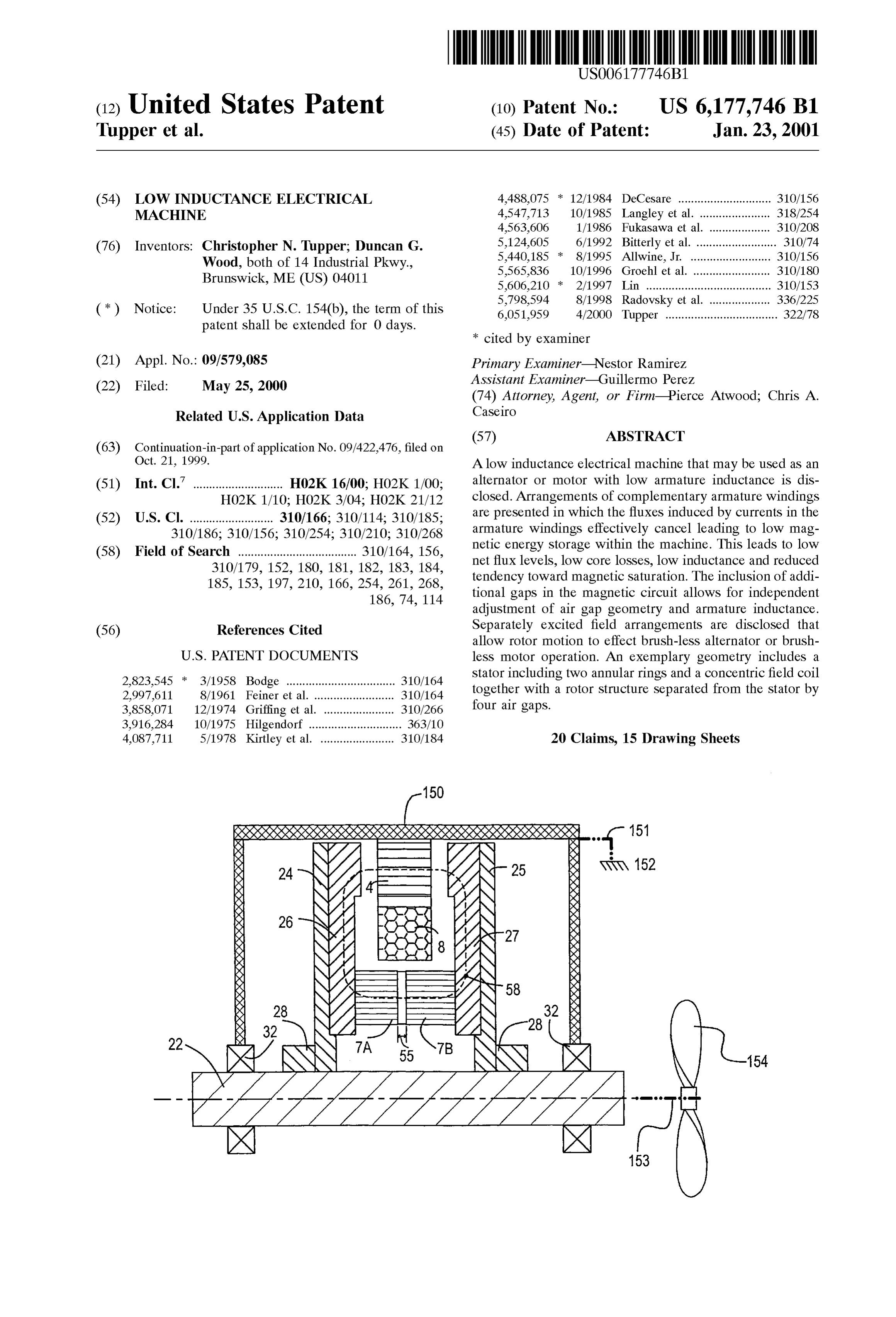
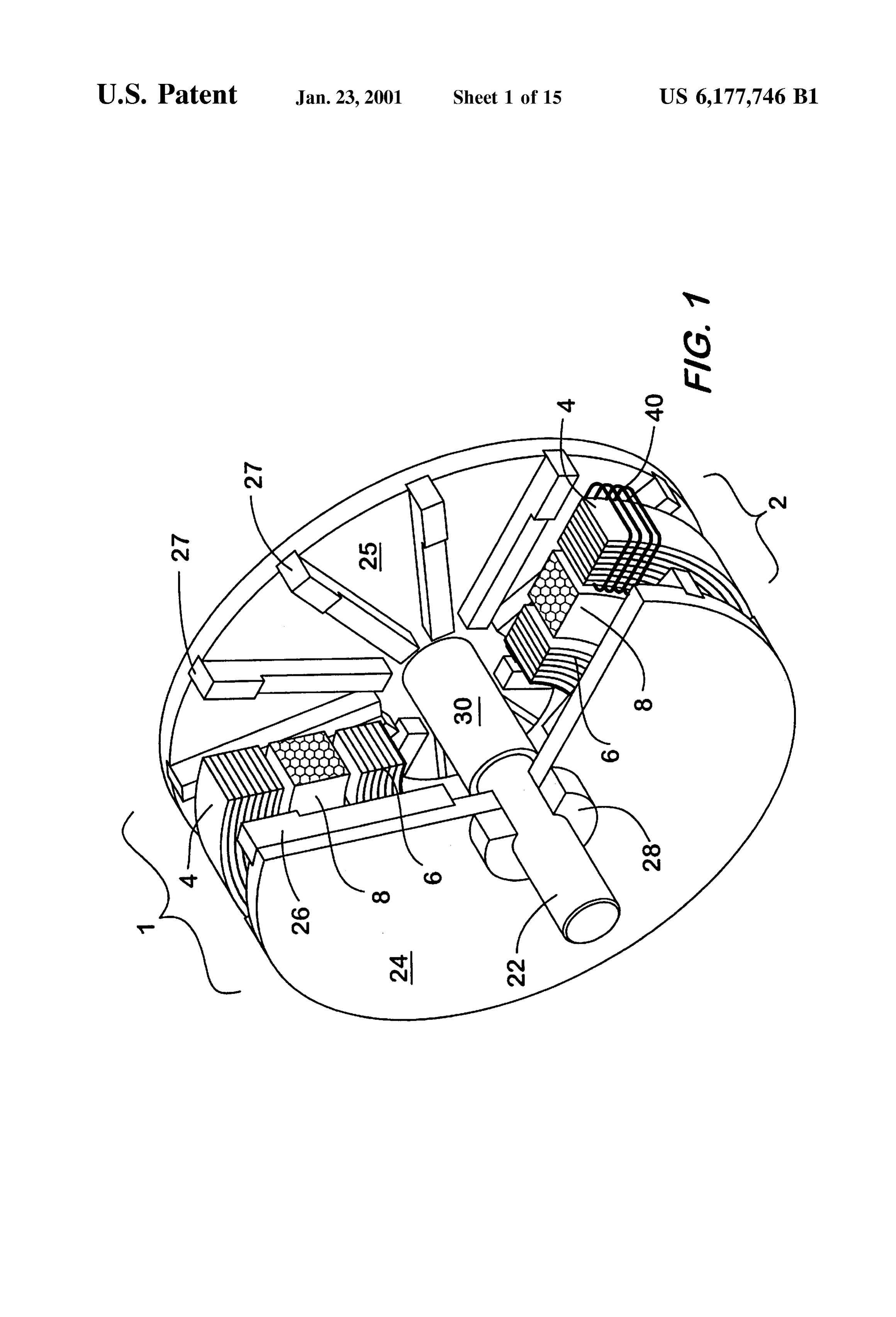
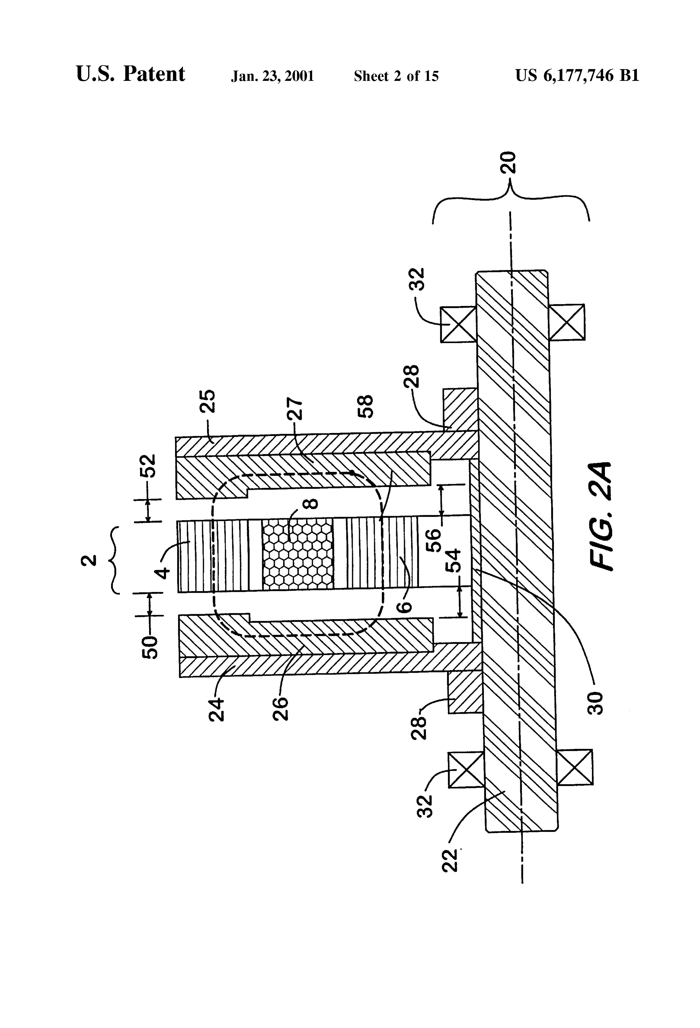
which distance is the same as one half of the circumferential FIG. 2A shows a cross-section of the preferred embodi pitch of the rotor pole bars on one disk, So that the rotor pole 45 ment of the low inductance electrical machine of the present bar and air gap adjacent to the Outer Stator ring alternates invention.
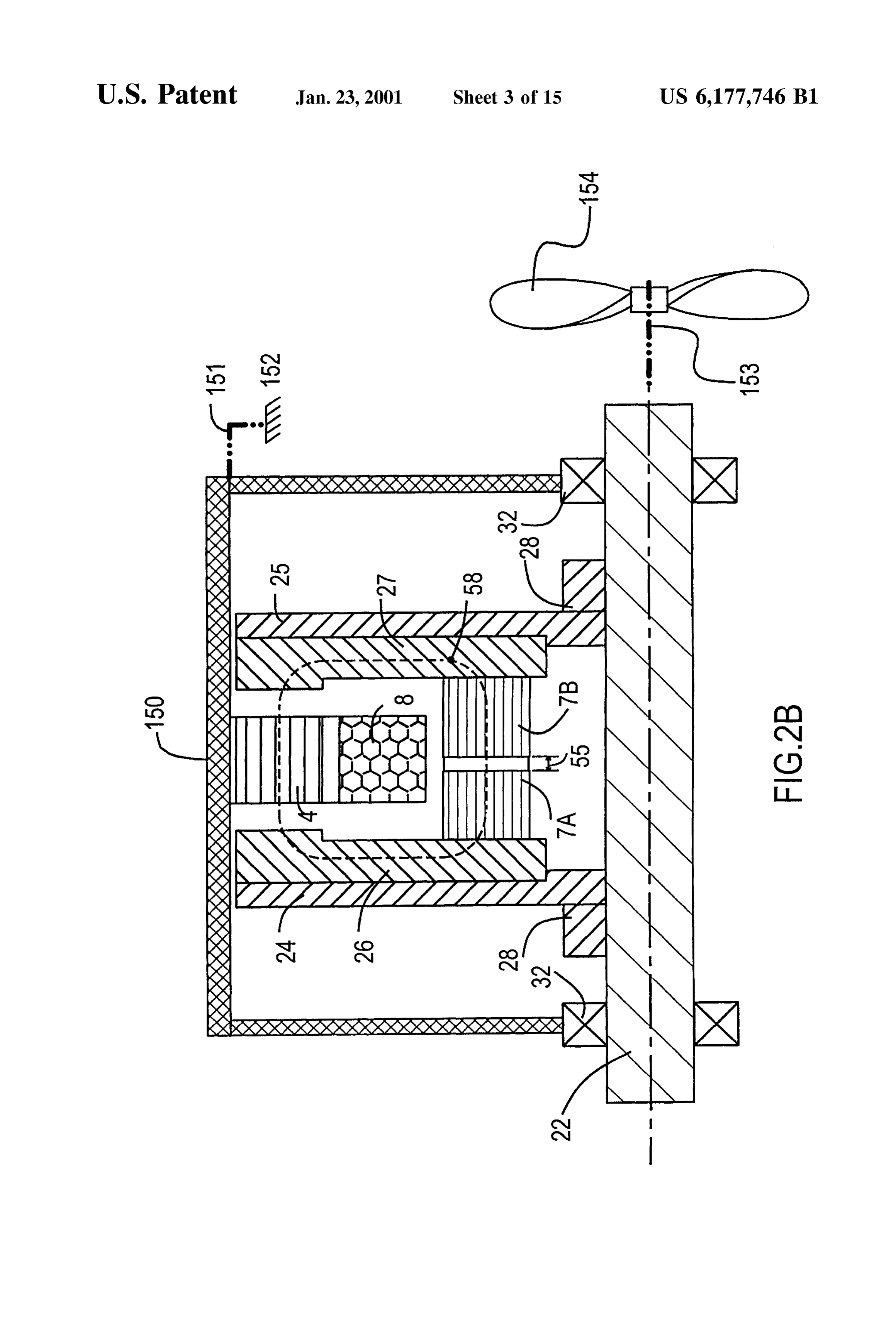
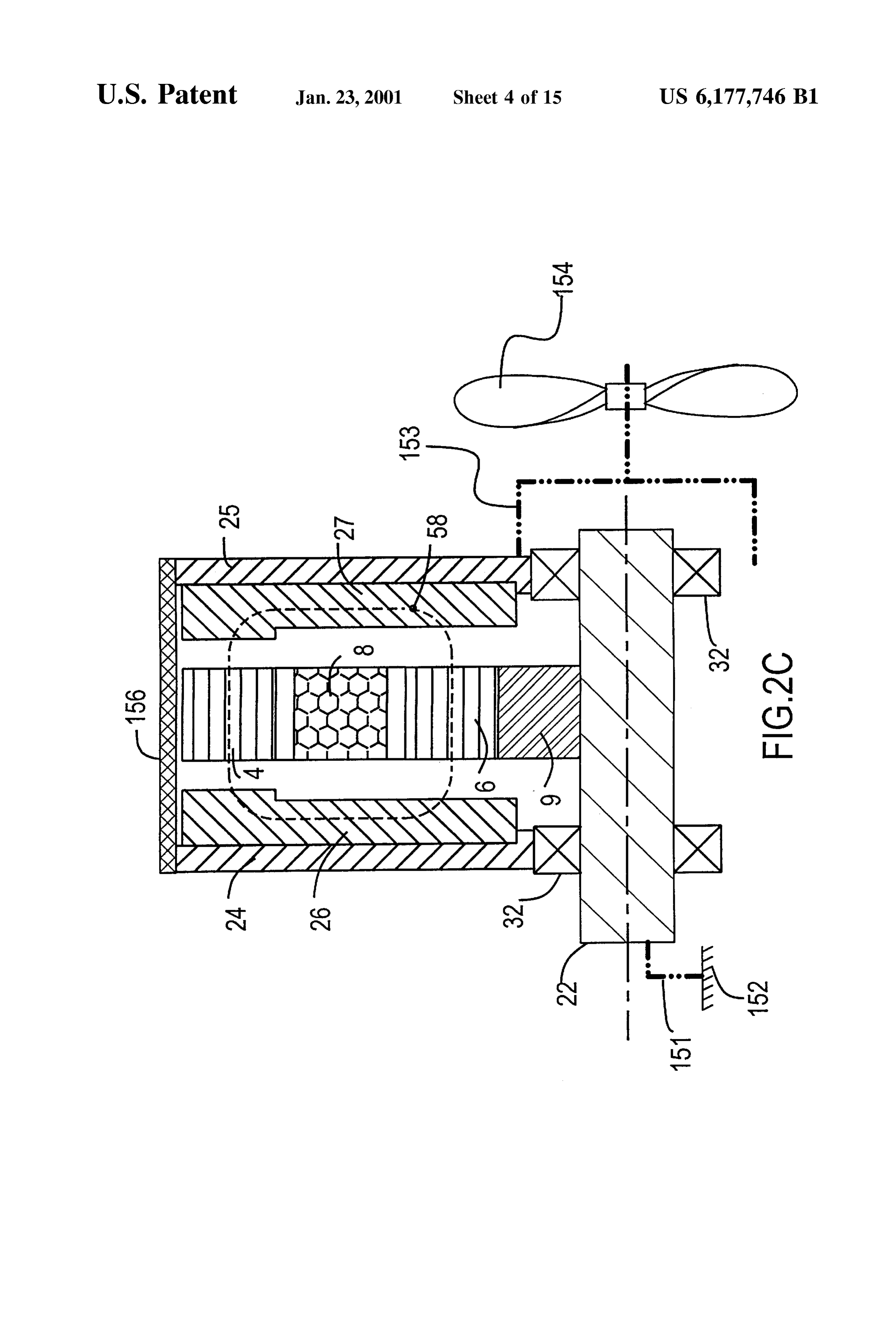
from one disk to the other as one progresses around the FIG. 2B shows a cross section of a first alternate embodi circumference of the outer Stator ring. The rotor pole bars ment with 3 Series air gaps in the magnetic pathway. can be magnetized to create rotor poles to carry excitation FIG. 2C shows a croSS Section of a Second alternate flux induced by current in the field coil. Armature coils are 50 embodiment.
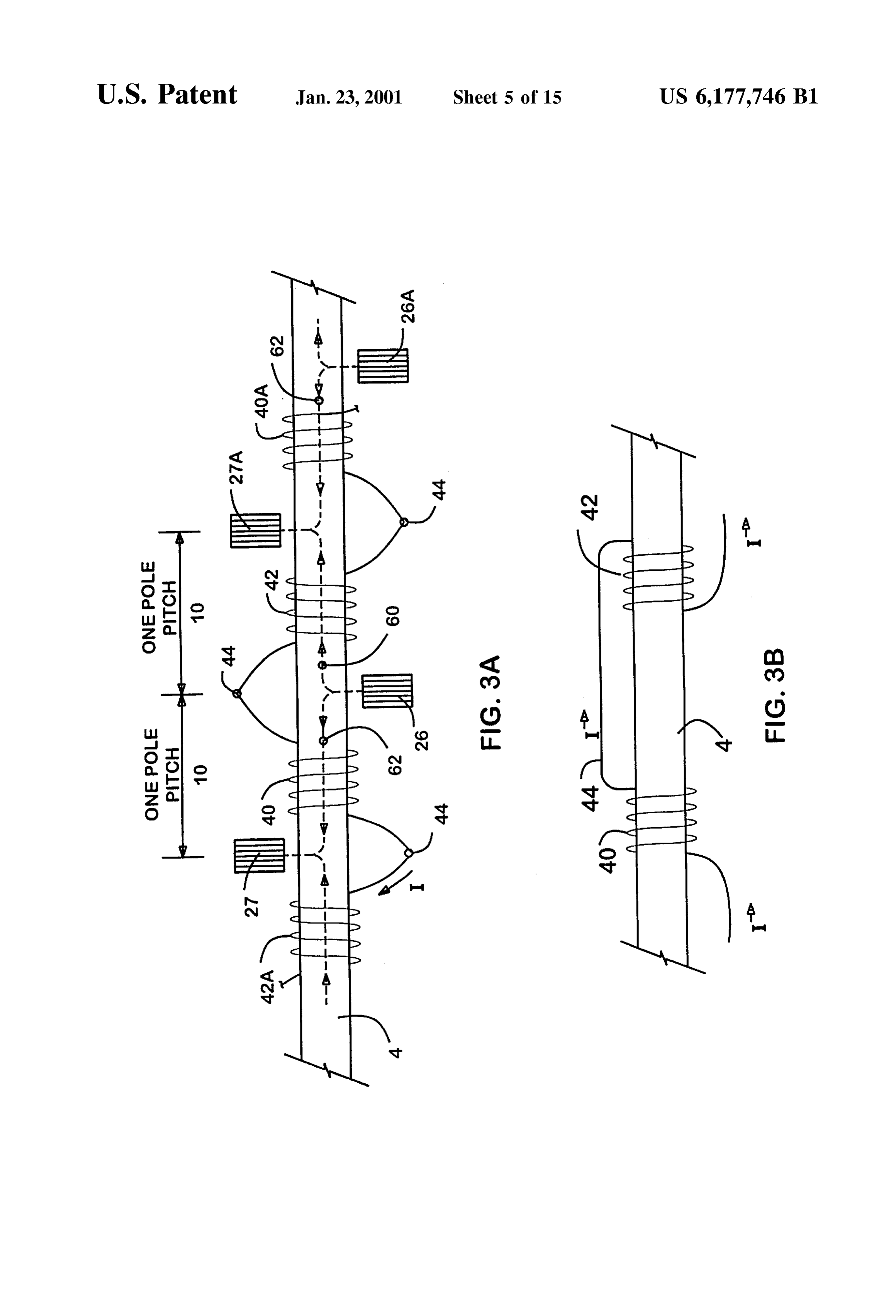
provided for one or more phases. Armature coils of each FIG.3A shows a developed view along the circumference phase are wound in complementary pairS Spaced evenly around periphery of the Stator, each member of the comple of the outer stator ring of the preferred embodiment mentary pair being wound in opposite direction and con FIG. 3B shows an alternate configuration of the armature nected in Series Such that the magnetic fields induced by a 55 windings in the preferred embodiment. current in the windings would be of equal magnitude but FIG. 4A is a Schematic diagram of the magnetic pathways opposite Sense in each winding and thus cancel. There through the outer Stator ring and the direction of flux flow should be one pair of complementary windings for each generated by load current in a pair of complementary phase for each pair of rotor pole bars. Winding for other armature windings in the preferred embodiment. phases should be arranged similarly, but angularly displaced 60 FIG. 4B is a schematic diagram of multiple pairs of around the circumference by an appropriate fraction of the complementary armature windings Spaced around the cir pole spacing to effect the desired electrical phase relation cumference of the outer Stator ring in the preferred embodi ships. ment.
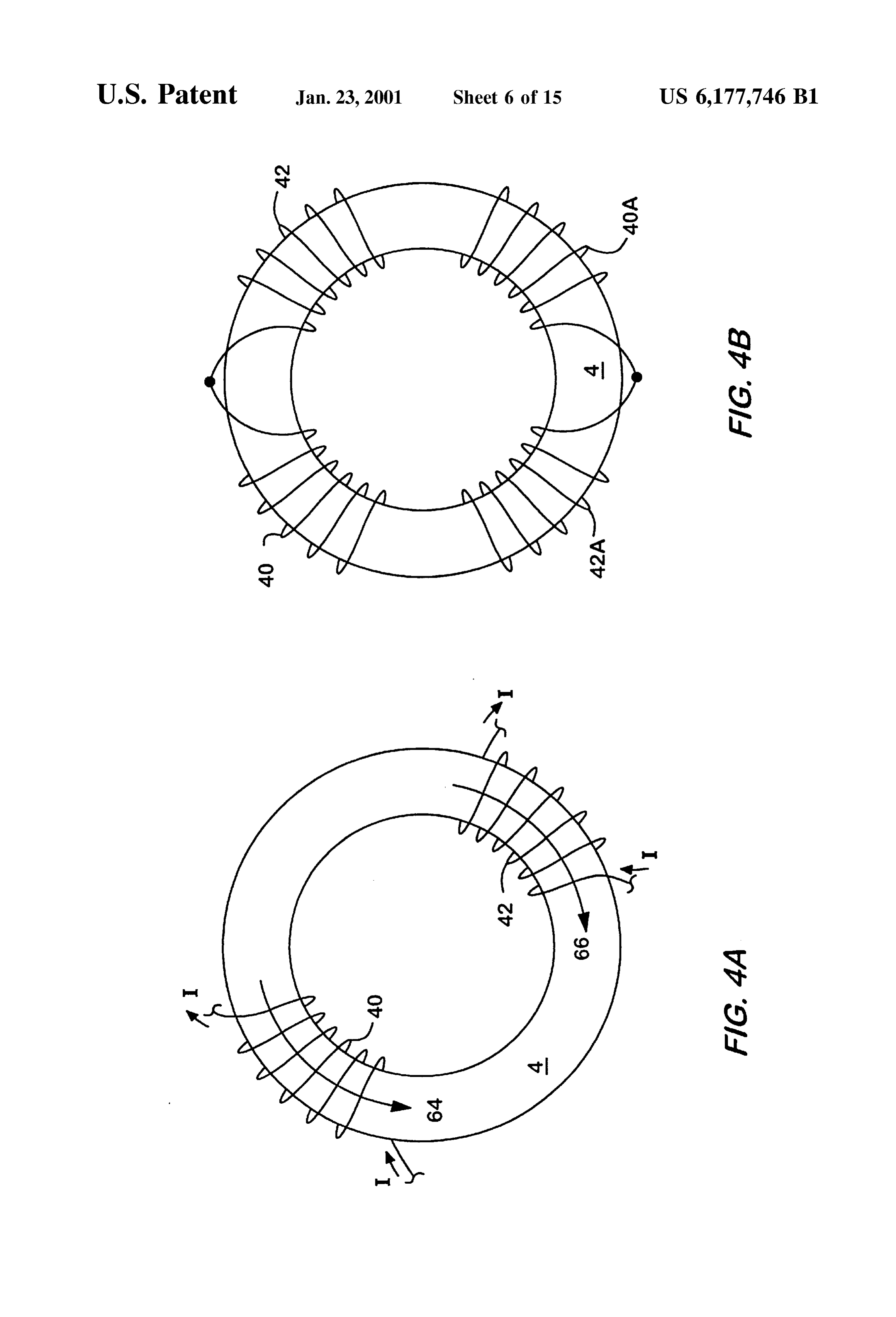
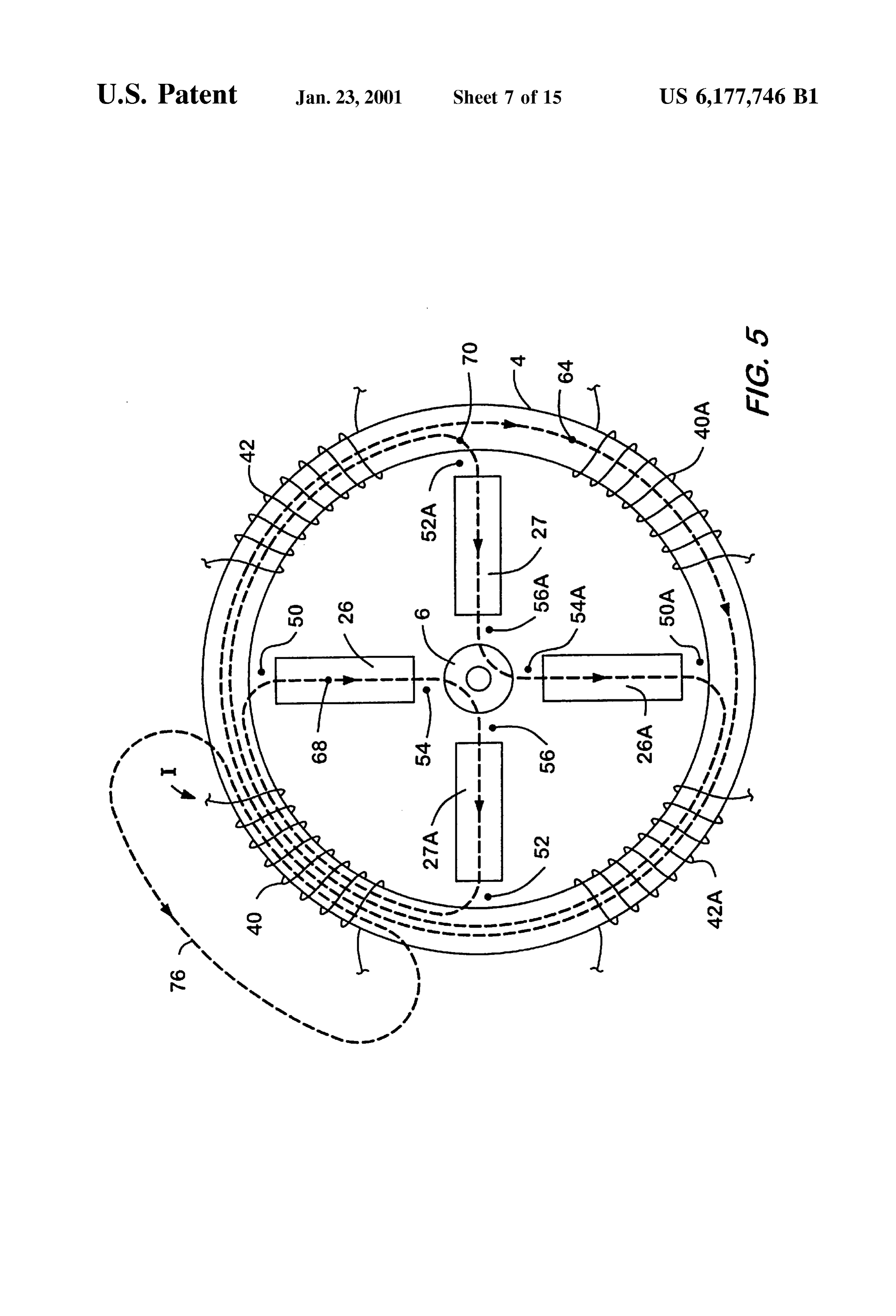
The present invention establishes a particular Series mag FIG. 5 is a Schematic diagram of the magnetic pathways netic pathway for magnetic flux induced by currents the field 65 through the rotor and the direction of flux flow induced by coil and armature windings. The flux path is axial and load current in a poloidal armature winding in the preferred circumferential through the armature Structure, then Serially embodiment.
Page 20
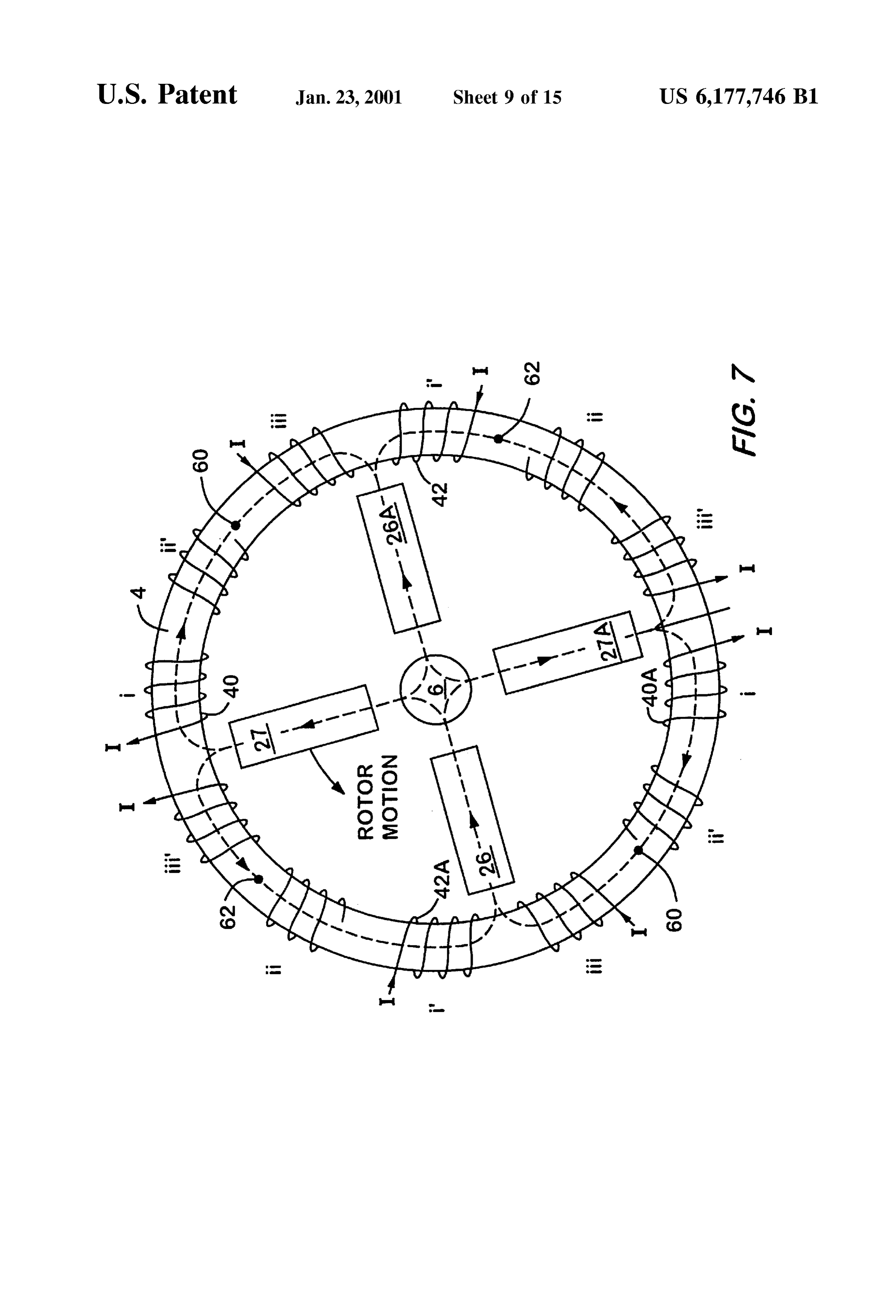
FIG. 6 includes FIGS. 6A-6F that show a scheme for FIG. 2A shows a cross section of the alternator. Means 32, analyzing the mutual inductance of rotor flux flows using Such as bearings, are provided to maintain the axial and various configurations of poloidally wound armature coils in radial position of the rotor assembly 20 relative to the stator the preferred embodiment. assembly 2 when shaft 22 is rotated relative to the stator FIG. 7 shows one method of winding three phases around assembly 2. FIG.2A also shows the axial components of the the outer Stator ring in the preferred embodiment. magnetic path 58 through the stator assembly 2 and rotor pole bars 26 and 27. The amount of flux flowing in magnetic
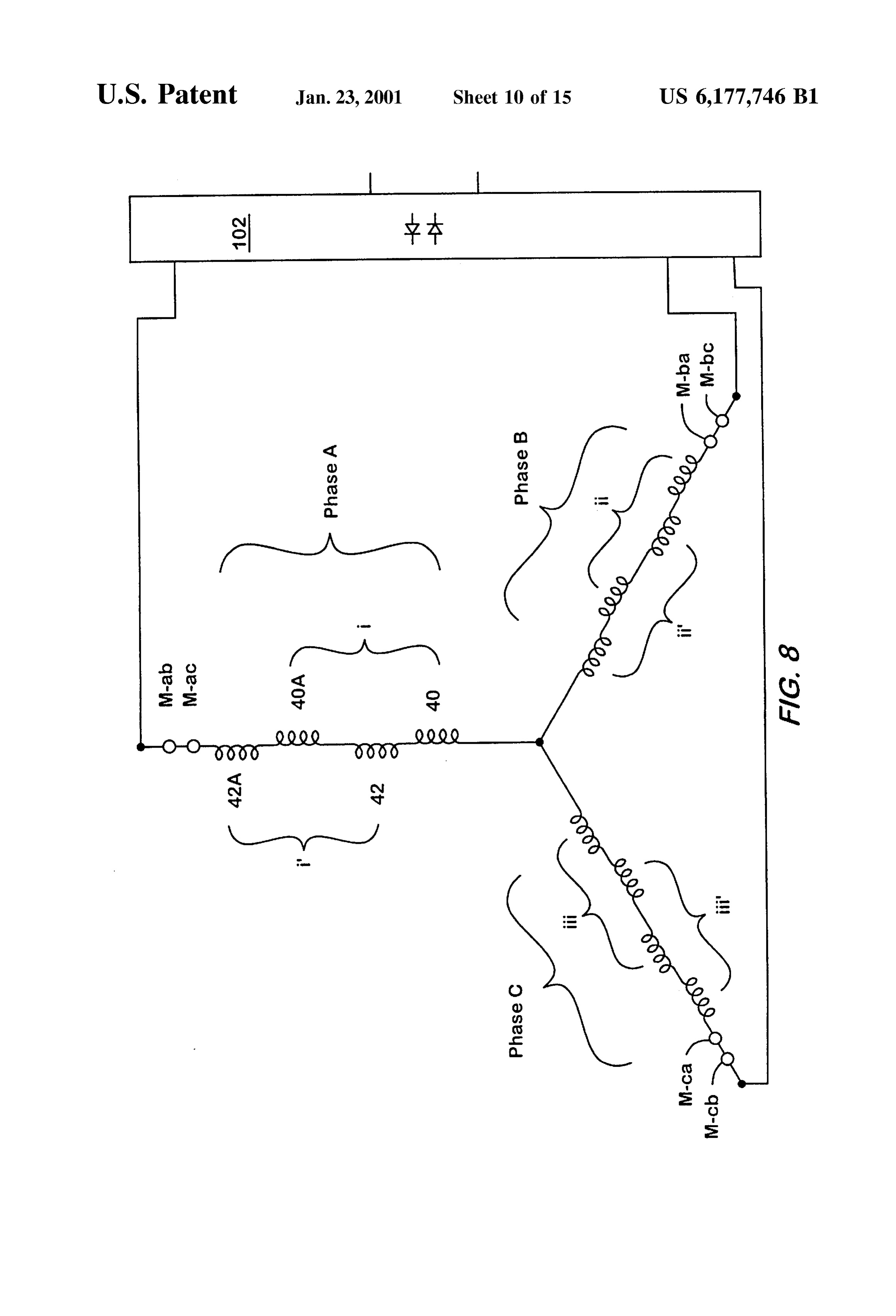
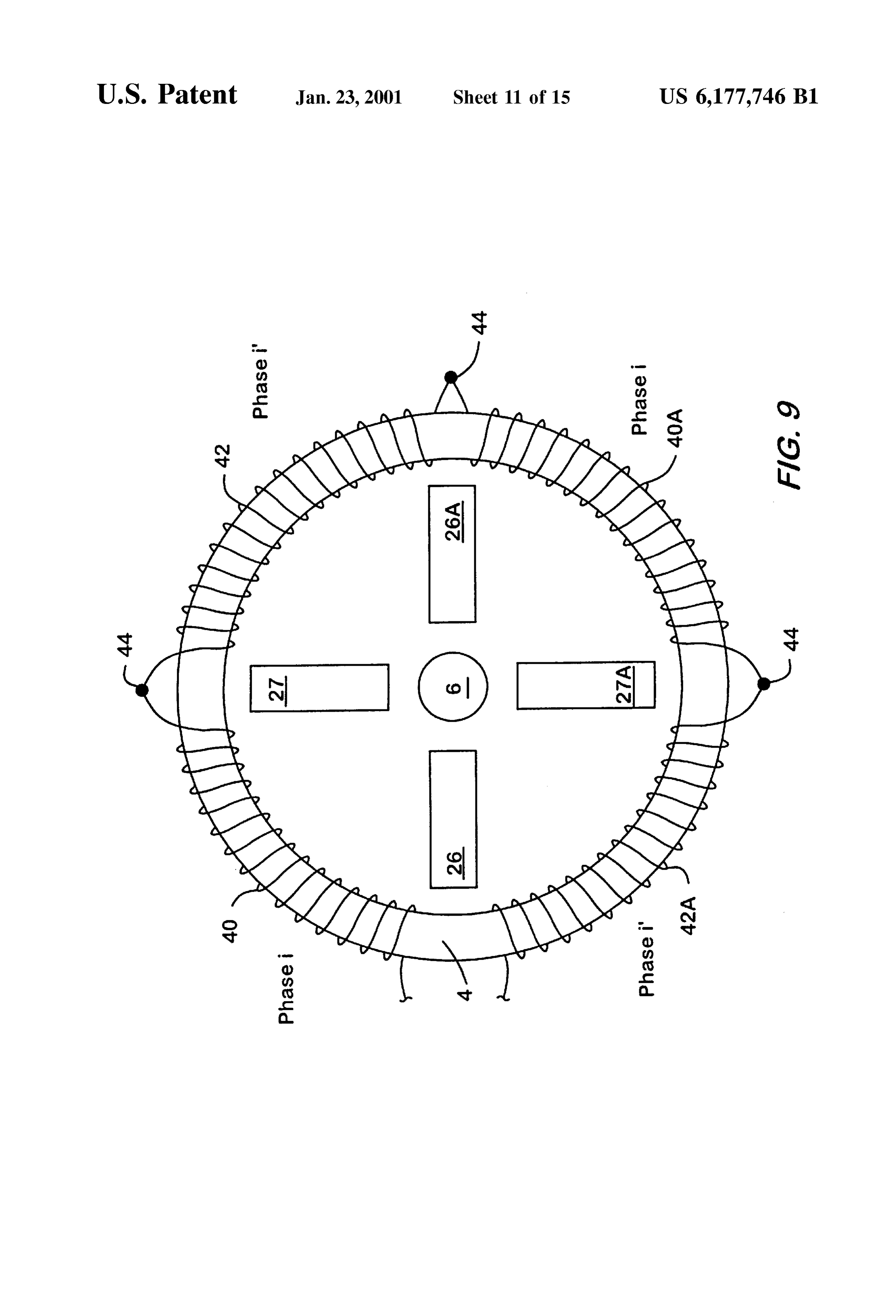
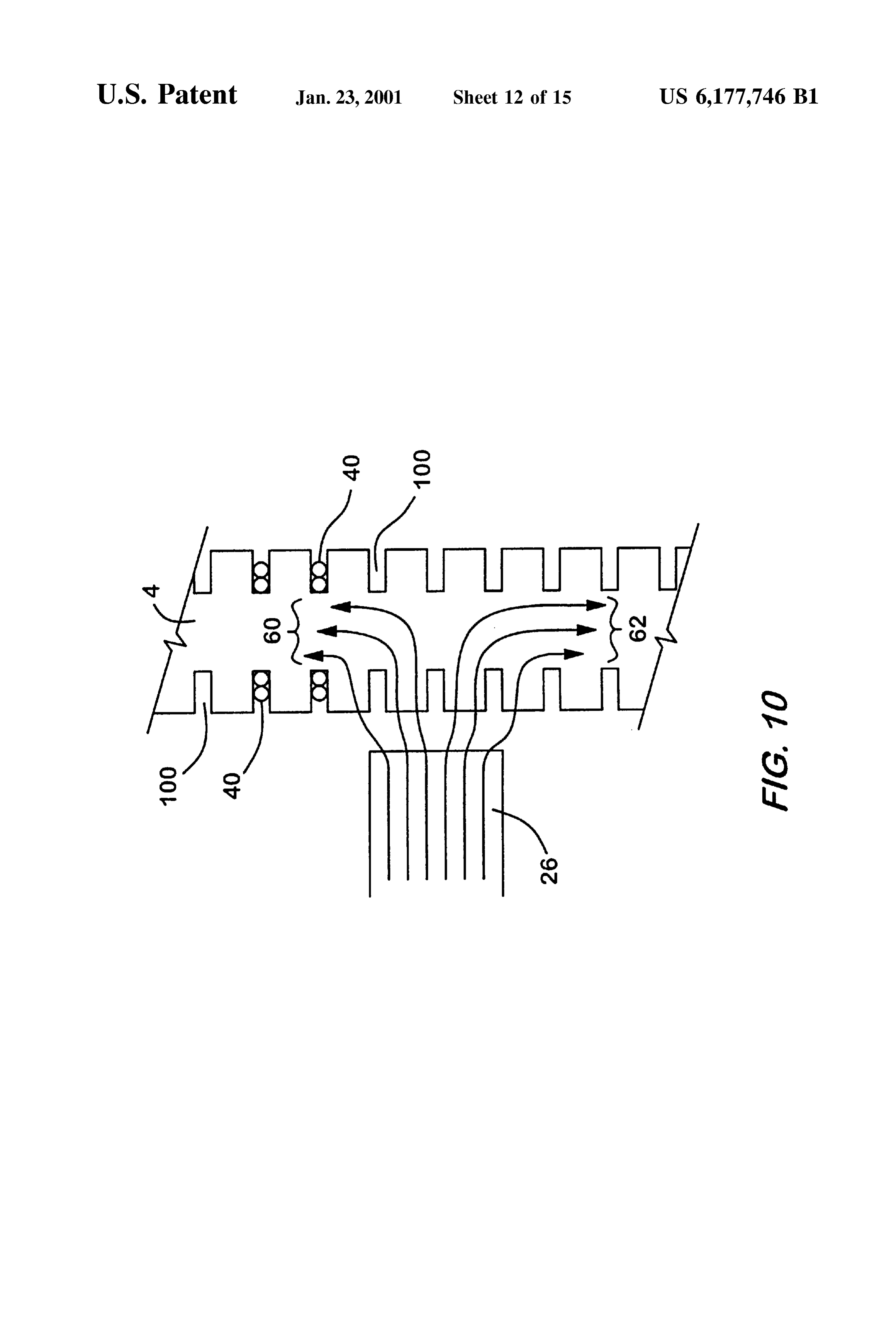
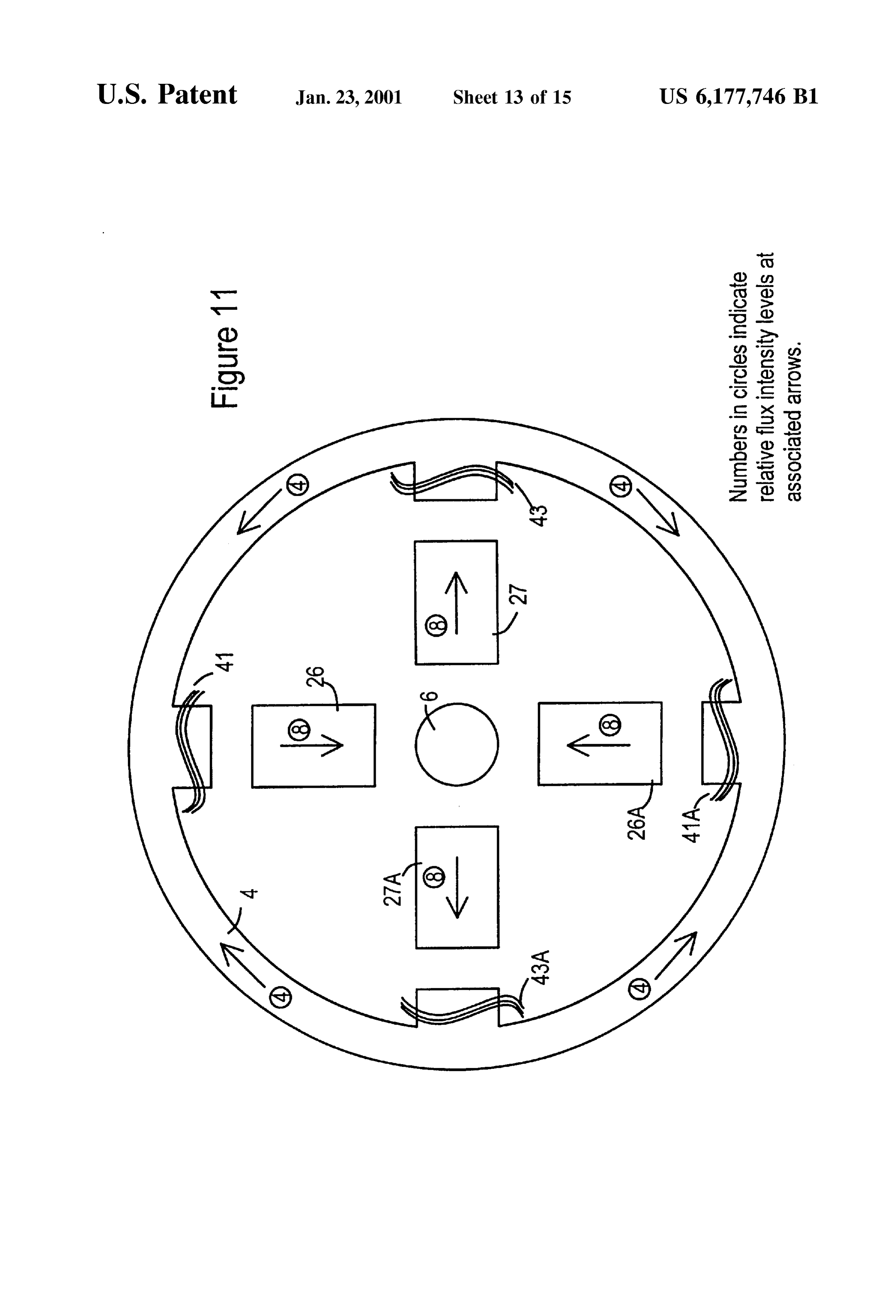
FIG. 8 is a Schematic diagram of one method of connect path 58 is controlled by the excitation of the field coil 8 and ing a multiphase alternator winding to an external rectifier in the magnetic reluctance of the path which in turn is primarily the preferred embodiment of the present invention. controlled by the reluctance of the two axial air gaps 54 and FIG. 9 shows an alternate method of winding one of 56 between the rotor pole bars 26 and 27 and the corre Several phases around the Outer Stator ring in the preferred sponding faces of the inner Stator ring 6 and the reluctance embodiment. of the two axial air gaps 50, 52 between the rotor pole bars FIG. 10 shows a detail of slots in the outer stator ring to 26 and 27 and the corresponding faces of the outer Stator accommodate armature winding coils. 15 ring 4. More generally, these air gaps 50, 52, 54 and 56 are FIG. 11 presents the results of an analysis of the mutual high reluctance portions of magnetic path 58 and may be inductance of rotor flux flows based on radially oriented gaps (54toand referred as magnetic gaps. AS shown in FIG. 2A, inner air 56) may be of a different axial lengths than armature coils.
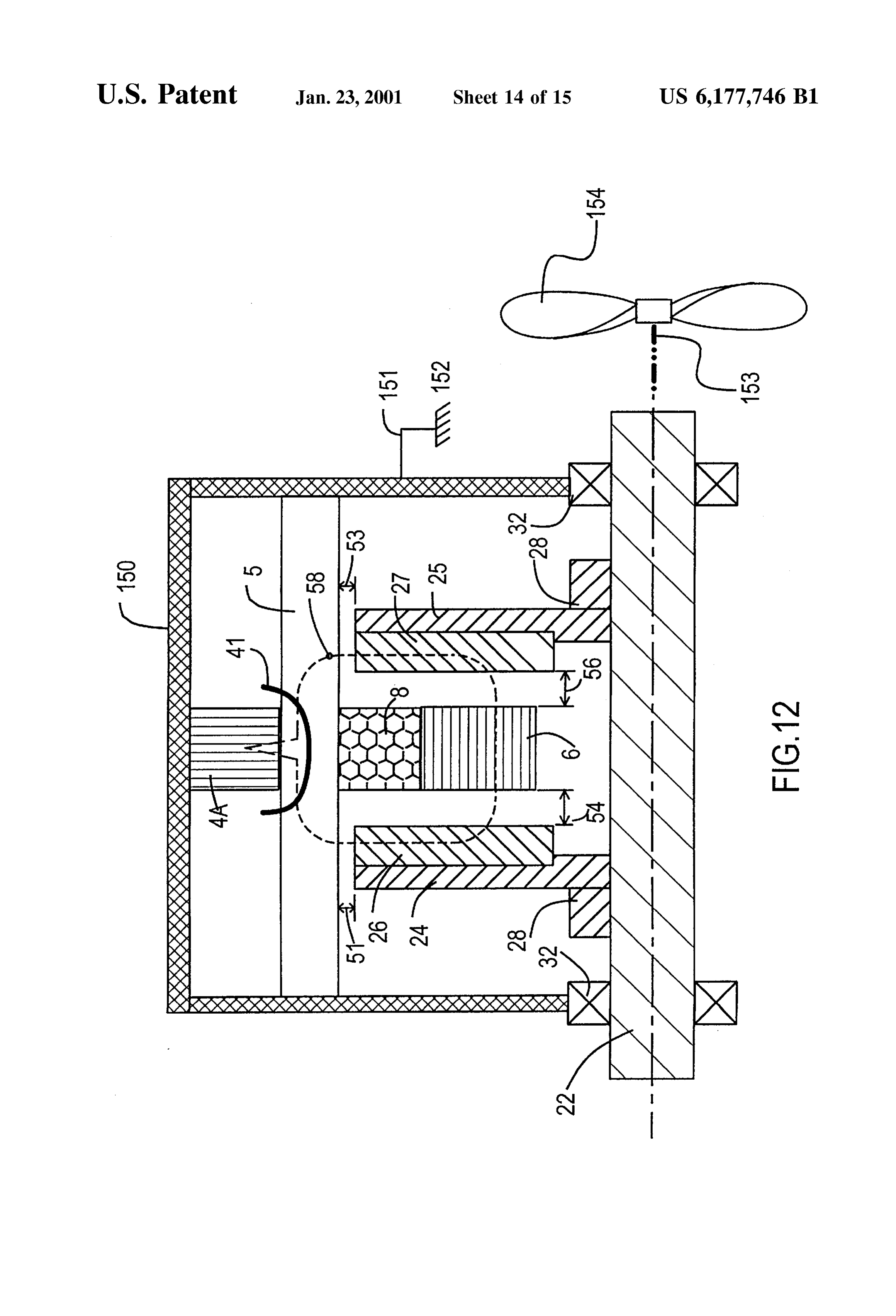
FIG. 12 shows a cross section of a third alternate embodi outer air gaps (50 and 52.) Designs with only two air gaps ment using radially oriented poles. near the Stator, Similar to air gaps 50 and 52, present a more usual configuration for a magnetic path. Adding the two
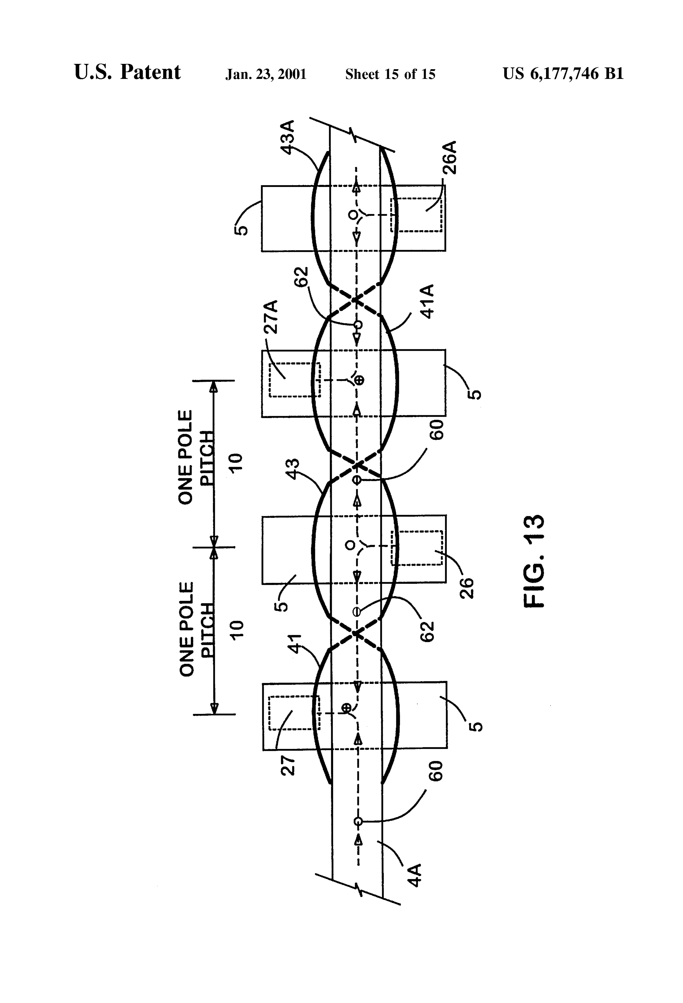
FIG. 13 shows an expanded circumferential view of the additional air gaps, 54 and 56 in Series in the magnetic path third alternate embodiment. 58 increases the excitation needed in the field coil but
DETAILED DESCRIPTION OF PREFERRED
provides the following benefits:
EMBODIMENTS OF THE INVENTION 25 (a) The added reluctance of air gaps 54 and 56 reduces the reaction flux that flows in magnetic path 58 when
In a first embodiment, the low inductance electrical excited by the output current in the armature windings. machine of the present invention is configured as a high This reduced reaction flux flow in the field magnetic frequency alternator. Referring to FIG. 1, the low output path reduces the magnetic energy Stored in this path inductance electrical machine 1 of the present invention resulting from the output current and thus is one includes a Stator assembly 2 including an outer annular ring important Step in reducing the inductance of the output 4 and an inner annular ring 6, both made Substantially of circuits of this device.
laminated electrical or magnetic Steel or other Suitable (b) The dimensions of outer air gaps 50 and 52 control the magnetic material with low core loSS characteristics in order pattern of air gap flux between the outer Stator ring 4 to minimize eddy current losses and hysteresis losses in the 35 and the rotor bars 26 and 27. As the axial lengths of Stator, and in this embodiment manufactured by making a outer air gaps 50 and 52 are increased the pattern of Spiral winding of appropriate material. An annular field coil leakage flux spreads further along the circumference of winding 8 of insulated copper wire or other Suitable con Outer ring 4, bypassing the intended pathway through ductor is located coaxially between the two Stator rings 4 and the armature coils and detracting from the performance 6, and provides means by which the Stator and rotor may be 40 of the machine. It is beneficial to be able to increase the excited by an external current Source. Armature windingS 40 reluctance of the magnetic pathway 58 in order to are wound poloidally around Sections of the outer Stator ring reduce the output inductance of the machine; at the 4 in a specific manner that will be detailed later. The outer Same time it is desirable to maintain the Small axial annular ring 4, in conjunction with the armature windings lengths of outer air gaps 50 and 52 in order to minimize 40, acts as armature for this device. All of these stator 45 leakage flux. The introduction of inner air gaps 54 and elements, 4, 6, 8, and 40 are held together firmly and held 56 allows the reluctance of the magnetic pathway 58 to stationary. The stator elements 4, 6, 8, and 40 may be glued be adjusted without changing the axial lengths of the together with materials like epoxy or Secured by mechanical outer air gaps 50 and 52. This provides for a new degree means Such as radial pins and held Stationary by attachment of independence between the level of leakage flux and to an external housing. 50 the armature inductance.
The low output inductance electrical machine 1 also (c) AS is well understood, in the absence of an air gap, flux includes a rotor assembly which includes a common shaft flow tends to concentrate on the inner edges of corners 22, which may preferably be made of non-magnetic in a magnetic pathway, thereby creating localized areas material, and two rotor disks 24 and 25, which may prefer of increased flux intensity; Such areas are prone to ably be made of non-magnetic and poorly conducting 55 magnetic Saturation and higher core losses. The intro material, each rotor disk also having Secured to it an duction of air gaps 54 and 56 forces the flux to spread identical number of rotor pole bars 26 and 27 oriented out across the width of the air gap thereby utilizing the radially and made entirely of laminated electrical or mag magnetic pathway more evenly, reducing localized netic Steel or other Suitable magnetic material with low core concentrations, Saturation, and core losses. loSS characteristics in order to minimize eddy current losses 60 (d) For a typical two air gap machine, without the air gaps and hysteresis losses in the rotor pole bars. The rotor 54 and 56, the part that is the inner ring 6 of the stator assembly may also include an optional axial Spacer 30 that of this invention would be replaced with a similar part may be made of non-magnetic material and which Serves to attached to the rotor instead of to the stator. It would maintain the axial spacing of the two rotor diskS 24 and 25. then be necessary to maintain a radial clearance The rotor is also fitted with means 28 to fix the rotor disks 65 between such a rotor part and field coil 8 so that it could 24 and 25 to the shaft to maintain the axial and rotary rotate clear of interference with the stator. In this positions of the disks. present invention the introduction of air gaps 54 and 56
Page 21
allows inner ring 6 to be a fixed part of the stator, with Spacer elements 156 which are arranged at the outer radius no radial clearance requirements between itself and the of the rotor disks to rotate clear of the Stator Structure and to field coil and with no requirements that the construction provide resistance to the magnetic forces of attraction of inner ring 6 withstand the centrifugal forces from between the rotor bars 26 and 27 and the outer annular ring rotation. 4. Elements 156 may be a Single complete ring or a number (e) Construction is simplified relative to the present art in of individual elements spaced around the circumference of that the length of the air gaps can be controlled by the rotor disks. In this embodiment the rotor disks are Spacer 30 which is outside the magnetic pathway. allowed to rotate relative to the shaft by means of bearings Adjustments to the air gaps and reluctance of the 32 and the stator is fixed by means of a radial connector 9 magnetic pathway can be achieved without modifica to the shaft 22 which is in turn fixed to frame of reference tion of the laminated magnetic materials in the path 152. Rotary source of power 154 is coupled directly to the way. rotor disks.
(f) Construction is further simplified relative to the While it is traditional for the stator and casing to be the present art in that the shaft without rotor disks 24 and fixed and for the shaft and rotor to turn, only the relative 25 can be inserted through the center of the stator 15 motion between the Stator Structure and the rotor Structure is assembly 2, and then disks 24 and 25 assembled into essential for operation of the device and either element may place over the ends of the Shaft, independently posi fixed relative to the frame of reference as long as the other tioned with optional assistance by means of Spacer 30, turns.
and Secured by fixing means 28 and bearing means 32. In general the magnetic materials of the alternator would (g) It can be appreciated from FIG. 2A that the shaft 22, be laminated magnetic or electrical Steels or other Suitable spacer 30, rotor plates 24 and 25 are not essential magnetic material with low core loSS characteristics in order components of the magnetic path and can be made of to minimize eddy current losses and hysteresis. In order to non-magnetic and poorly conducting materials in order utilize the low core loSS properties of the laminated materials to reduce core losses in these areas. the flux should flow within the plane of each laminate or (h) The separation of the mass of the inner Stator ring 6 25 parallel to the curved Surface of each laminate and not have from the rotor assembly 20 allows the rotor assembly to components that flow perpendicular to the planes or Surfaces be relatively lightweight and have lower inertia com of the laminates. Induced Voltages and the resulting eddy pared with rotors in which the equivalent flux path, currents are oriented around changing flux lines in a plane represented by inner Stator ring 6, is included in the perpendicular to the flux lines. It is desirable that the rOtOr. laminations be perpendicular to the plane of eddy currents in It will be noted from FIG. 2A and other figures to follow order to have the inter-laminar resistance impede the circu that the arrangement of the magnetic path 58 in the alternator lation of eddy currents. It is undesirable for the lamination 1, wherein the outer stator ring 4, inner Stator ring 6, field to be parallel to the plane of components of the eddy currents coil 8 are all Stacked concentrically, and wherein the rotor Since Such components would then circulate relatively pole bars 26 associated with rotor disk 24 all have the same 35 unimpeded, causing large losses. FIGS. 1 and 2 show that magnetic polarity when the field coil 8 is energized, and the magnetic material laminates are all oriented Such that the wherein the rotor pole bars 27 associated with rotor disk 25 flux flows parallel to the surface of the laminates. The outer are all alike in having the opposite polarity, provides for a Stator ring 4 and the inner Stator ring 6 are preferably made minimal amount of leakage flux due to field excitation. This of spiral windings of magnetic material, So that the laminates leads to more optimal use of the magnetic material and lower 40 are essentially concentric with the axis of the shaft 22. Flux core losses than designs with large amounts of leakage flux, flow in these elements is axial and circumferential and Such as in claw pole designs. parallel to the curved Surfaces of the laminates. In Situations FIG. 2B shows a cross section of a first alternate embodi where the level of field flux in magnetic path 58 may be ment with a magnetic pathway with three magnetic gaps in amplitude modulated at a desired power frequency, care Series, two outer air gaps 50 and 52, and one inner magnetic 45 must be taken to prevent the layers of spiral wrappings of the gap 55. The inner ring is now comprised of two parts, 7A and inner Stator ring 6 or outer Stator ring 4 from shorting from 7B which are rigidly attached to the rotor structure and are one layer to another, Such short circuits amount to creating provided with radial clearance to allow rotation within the a closed conductor enclosing axial components of magnetic field coil 8 which is fixed to the Stator. Inner magnetic gap flux in pathway 58. As is well known, there will be signifi 55 may be an air gap or a non-magnetic spacer held firmly 50 cant Voltage and current induced into a closed conductor between the parts 7A and 7B. It will be understood that gap which encircles a time varying flux. Such currents are 55 might be placed between the rotor bars, 26, and one of the essentially eddy currents and waste power. The rotor pole inner ring parts, in which case parts 7A and 7B could be bars 26 are made of laminations of magnetic material which combined into a single part rigidly attached to the adjacent are Stacked in planes parallel to the plane containing the rotor bars 27 and rotor disk 25. This alternate embodiment 55 radial dimension through the center of the rotor pole bar 26 achieves the advantages a, b, e, fand gas outlined above but and the axis of the shaft 22. Similarly the rotor pole bars 27 does not realize advantages c, d and h outlined above for the are made of laminations of magnetic material which are preferred embodiment. Stacked in planes parallel to the plane containing the radial FIG. 2B also shows an outer casing 150 fixed to a frame dimension through the center of the rotor pole bar 27 and the of reference 152 by means 151 such as brackets and bolts. 60 axis of the shaft 22. The flux flow in the rotor pole bars 26 FIG. 2B also shows a source of rotary power 154, such as a and 27 is essentially radial with Slight axial components and windmill or vehicle engine, coupled to the shaft 22 by means this flow is fully within the plane of the laminates. 153 Such as belts and pulleys. For operation of the current FIG.3A shows a developed view along the circumference invention as a motor, element 154 could represent a rotary of the outer stator ring 4. In this invention, rotor disk 25 is load, Such as a fan blade or vehicle transmission. 65 shifted circumferentially one pole spacing 10 in relationship FIG. 2C shows a second alternate embodiment in which to rotor disk 24 so that rotor pole bars 26, 26A and rotor pole rotor diskS 24 and 25 are held apart by non-magnetic axial bars 27, 27A and their corresponding air gaps are Staggered
Page 22
along the circumference of outer Stator ring 4. ASSuming that tion threshold of the magnetic material the magnetic the field coil excitation is such that rotor pole bars 26 and response of the device will be non-linear. AS with many 26A act as north poles and rotor pole bars 27 and 27A act as electromechanical machines the present invention will Still South poles, FIG. 3A shows a simplified schematic of the function in the non-linear range caused by magnetic Satu direction and distribution of field induced flux elements 60, ration.
62 along the circumference of Stator ring 4. ESSentially the In FIG. 4A the load current in the armature pole winding flux from north pole bar 26 splits with half going clockwise 40 and the current in armature pole winding 42 will be of as flux flow 60 and half going counter clockwise as flux flow equal magnitude, and will induce flux flows 64 and 66 of 62, each to flow to the nearby South pole bars 27 and 27A. equal magnitude, but flowing in opposite circumferential As the rotor pole bars 26, 26A, 27, 27A, etc., move relative directions completely around the low reluctance material of to the circumference of Outer Stator ring 4 the field induced the Outer Stator ring 4. These equal but opposite flux flows, flux 60, 62 enclosed by any one armature winding, Such as 64 and 66 Superimpose and effectively cancel the inductive 40, will alternate in direction and this time variation in flux effects of this magnetic circuit relative to the armature will induce Voltage within the winding. Current.
To take advantage of this flux alternation, armature wind 15 While the Superposition of the equal but opposite flux ing 40 is positioned on the outer Stator ring 4 and wound a flows may be referred to as flux cancellation, in actual fact given number of turns in one direction, and complementary the two coils will still be linked by mutual inductance. A armature winding 42 is placed one pole spacing 10 away reactance Voltage of one volt in coil 40 will produce a along the circumference of the Outer Stator ring 4 and wound reactance Voltage of one volt in complementary armature the same number of turns but in the opposite direction So that coil 42. By their complementary Series electrical connection when the windings are connected in Series at reference point the net reactance Voltage will be Zero volts. This makes the 44 the Voltages caused by the change in flux as the rotor pole armature circuit behave as a Small value inductor bars 26, 26A and 27 and 27A move relative to the outer (theoretically Zero).
Stator ring 4 will augment each other. It will be clear that Complementary pairs of armature poles 40 and 42 are reference point 44 need not be a termination of the winding, 25 needed for this effective cancellation of circumferential flux but may be a point at which the direction of a continuous flows 64 and 66. The resultant flux intensity level (B field in winding reverses. Due to the spacing of the reversing pattern Tesla) in the circumferential direction within the outer stator of flux induced by the field excitation, there should be one ring 4 will be very low (theoretically zero) as a result of this complementary pair of armature windingS 40 and 42 for cancellation (Superposition) effect. The low resultant (net) each pair of complementary rotor pole bars 26 and 27. flux intensity level will allow the outer ring 4 to carry the FIG. 3B shows an alternate configuration of the armature reaction flux from high load currents without going into windingS 40 and 42 placed on the outer Stator ring 4 in magnetic Saturation. Eddy current and hysteresis losses complementary pairs and connected in Series to show that (core losses) in the outer ring 4 will be proportionate to the the same effect of complementary pairs of armature wind square of the low (net) flux intensity, and thus will be very ings can be achieved if windings 40 and 42 are wound in the 35 low. The resultant output inductance due to flux flowing Same physical direction around outer Stator ring 4 while the circumferentially all the way around the low reluctance path common connection point 44 is changed So that the load of the outer stator ring 4 will be very low (theoretically current “I” in armature winding 40 flows in a circumferential Zero). In contrast, without the cancellation effect of the flux direction of reversed Sense to the load current in armature induced by load current in complementary armature winding winding 42. 40 42, the flux intensity level, the tendency toward magnetic In FIGS. 3A and 3B the complementary pairs of windings Saturation, and the core losses in outer ring 4 due to load 40, 42 and 40A, 42A, etc., refer to a single-phase armature current in armature winding 40 would all be substantial and circuit. Complementary pairs of windings for additional contrary to the objectives of this invention. output phases, as needed, may be placed on the Outer Stator The advantages of low inductance, low flux intensity ring 4, the position of each phase being offset along the 45 levels with low tendency toward magnetic Saturation, and circumference of the outer Stator ring 4 by the appropriate low core losses are obtained at each location within the fraction of the pole spacing to effect the desired electrical magnetic circuits where the fluxes Superimpose to effec phase shift. Such additional phase windings can be wound tively cancel. The advantages are proportionate to the directly over each other, as will be described later, or over amount of effective cancellation except for core losses that Separate Segments of the outer Stator ring 4. In each phase 50 are related to the net flux intensity level Squared. the Spacing between complementary windingS 40 and 42 It will be further appreciated from FIG. 4B that additional should be one pole spacing 10. Due to the Spacing of the complementary pairs of armature windingS 4.0a and 42a can reversing pattern of flux induced by the field excitation, be placed on the Outer Stator ring 4, members of the pairs there should be one complementary pair of armature wind Spaced one pole Spacing apart and that each complementary ingS 40 and 42 for each phase for each pair of complemen 55 pair will have a net effect of Zero inductance on itself and a tary rotor pole bars 26 and 27. mutual inductance of Zero on any Similar complementary Superimposed on the flux induced by the field excitation pairs located around the circumference of outer Stator ring 4. will be the flux induced by any load currents flowing in the In turn, it follows that the mutual inductance of a Series of armature coils. At flux intensity levels below the magnetic complementary pairs of armature windings and the mutual Saturation threshold of the magnetic material the effects of 60 inductance between phases made of Such pairs due to these different flux fields may be analyzed separately and circumferential flux flows 64 and 66, taken together, will be added together linearly. For electrical and magnetic Steels (theoretically) Zero.
that threshold is often near 1.2 to 1.5 Tesla. For clarity the It must be emphasized that without the arrangement of rest of this description of the preferred embodiment follows complementary pairs 40 and 42 high levels of net flux would the assumption that the device is operating within its linear 65 flow around the circumference of the outer Stator ring 4 due range. However, it will be understood that where the flux to the low reluctance of ring 4. This would result in high intensity level of Superposed flux fields exceeds the Satura levels of magnetic intensity in the magnetic material, and
Page 23
Saturation at relatively low levels of output current. In this reduce the net inductive effect from induced rotor-path flux. undesirable arrangement the output inductance of the alter It is understood that the typical addition of four series coils nator would be very high and the mutual inductance of the of equal turns on a common magnetic pathway leads to various output phases would be very high. It will also be mutual inductances that combine to create a total inductance appreciated that the Outer Stator ring 4 could be a closed 5 of (4 Squared) 16 times the inductance of a single coil. Here, shape other than a toroid and Still manifest the properties of however, the arrangement of complementary pairs of cancellation of flux due to complementary pairs of armature windings, one pair of windings per pair of rotor pole bars, coils 40 and 42. results in a Substantial cancellation of inductive effects. In FIG. 5 presents a schematic of the multiple flux paths the case shown the four windings combine to reduce the net excited by current in armature winding 40. It can be seen that flux in each winding to one half of its own Self inductance in addition to circumferential flux flow 64, discussed above, flux, the total Series inductance of the four windings is only there is other flux induced by the current in armature coil 40 twice that of a Single winding.
and this flux does not complete the entire circuit through the The inventors have discovered that this condition of the low reluctance material of outer Stator ring 4 but will effective cancellation of inductance for induced rotor-path complete a parallel circuit through a higher reluctance 15 flux holds for any case where there is one complementary pathway including the air gaps and the rotor (load induced pair of armature windings, members of the pairspaced along rotor flux, see flux flow 68 and 70), or locally through the air the circumference of the outer Stator ring 4 at one pole near the coil 40 (local flux, see flux flow 76). Additional spacing 10, for each pair of rotor pole bars. The inventors design considerations, explained below, will minimize the have also discovered that the total series induction of the inductive effect of these alternate flux paths. output rises arithmetically with the number of winding pairs, In FIG. 5, load induced rotor flux flows 68 and 70 show that is the inductance of Seven complementary winding pairs the magnetic pathways in the rotor taken by flux induced by Spaced around Seven rotor pole pairs is Seven times the load current in armature winding 40. Magnetic energy is inductance of one winding pair spaced around a single rotor Stored along these flux paths, particularly in the high reluc pole pair.
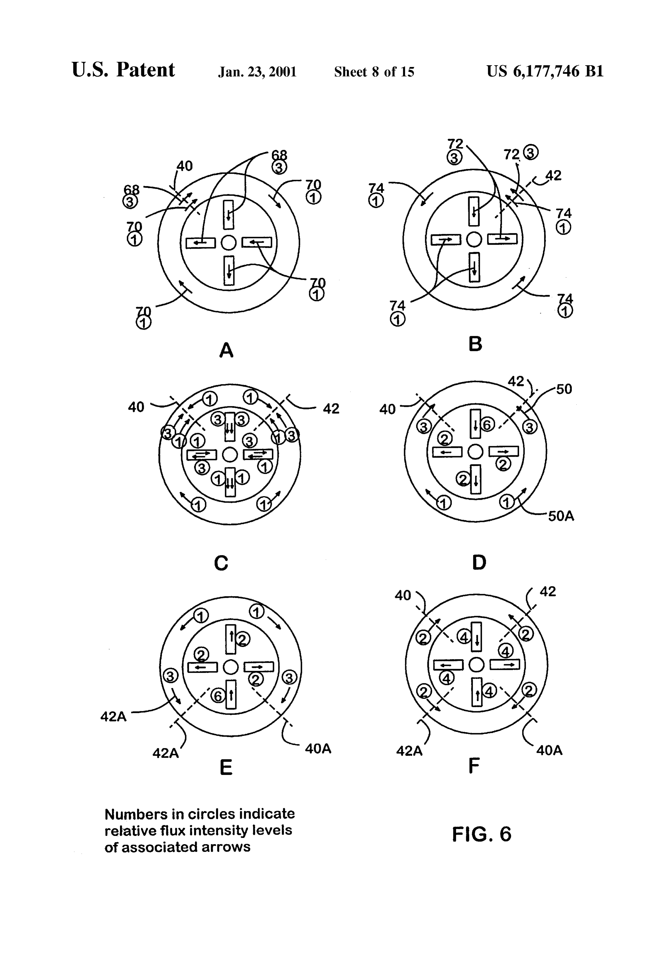
tance air gap areas. This energy Storage would manifest as 25 For purposes of clarity, FIGS. 5 and 6A-6F have been laid Self inductance in armature winding 40. Also Since a portion out so that the rotor pole bars 26, 26A, 27 and 27A and their of this flux flows through armature windings 42 and through asSociated air gaps are shown Stacked radially inside the armature windings from other phases there will be mutual outer Stator ring 4. This is Similar to the position of rotor inductances between armature winding 40 and other arma poles in a claw pole type alternator and the analysis given ture windings. here could apply to poloidally wound alternators with claw FIGS. 6A-F shows a schematic for analyzing the self and pole rotors as well as to alternators with the rotor Structure mutual inductance of rotor flux flows using various configu shown in FIGS. 1 and 2A and 2B. Furthermore, while FIGS. rations of armature coils. The numbers in circles refer to the 5 and 6A-6F show the four air gap configuration of this relative flux intensity levels represented by the associated invention, the conclusions of the analysis would not be arrows, the flux intensity values are based on Similar amp 35 altered by the elimination of air gaps 54, 54A, 56 and 56A, turns of excitement from load current in each coil. FIG. 6A etc., as in the more usual two air gap design. shows the components of flux in each branch of the flux flow There will also remain the effect of local flux 76 of FIG. path for rotor flux flows 68 and 70 induced by the load 5 for each armature winding resulting in additional Self current in armature coil 40. (Note that circumferential flux inductance of the output. Because of the long, high flow 64, discussed above, is not shown in FIGS. 6A-6F) 40 reluctance, air return path of the local flux 76, the flux flow Note that the relative flux intensity at coil 40 is “4”. FIG. 6B 76 will be low compared to the flux levels carried in the low shows a similar analysis for flux flows 72 and 74 induced by reluctance magnetic materials. It must also be noted that the load current flowing through complementary armature local flux 76 may link with other nearby armature windings winding 42, note the change in direction of flux flow due to and result in Some net mutual inductance. It will be appre the reversed winding direction of armature winding 42. 45 ciated that these net inductances will be Small compared to FIG. 6C shows the flux flows, 68 and 70, Superimposed the output inductance that would be developed without onto flux flows 72 and 74. FIG. 6D shows the net flux flow; cancellation. The net result will be low output inductance for flows in opposite directions tend to “cancel” the effect of this alternator, coupled with low core losses and capability each other. It can be seen that the induced rotor path flux to handle large load currents without Saturation of the caused by equal currents in the complementary pair of 50 magnetic material or pathways. FIG. 7 shows one method of armature windings 40 and 42 do not fully cancel but will winding three phases around the outer Stator ring 4. A Single have a net inductance and a high flux intensity level in Some phase is shown as two Sub-phases (i,i) where elements 40, of the air gaps, in Some Sections of the outer Stator ring 4 and 40A, etc., wound in one direction, constitute Sub-phase i and in some of the rotor pole bars. Note, however, that the the complementary elements 42, 42A, etc., wound in the relative flux intensity at coils 40 and 42 are now reduced to 55 opposite direction, constitute Sub-phase i'. A Second phase a net of “3. contains two similar Sub-phases ii and ii'. A third phase also FIG. 6E shows the net flux caused by a second comple contains two Sub-phases iii and iii'. In this figure the coils of mentary pair of armature windingS 40A and 42A placed each armature winding are concentrated along a discrete diametrically on the Outer Stator ring 4 from armature Section of the circumference of outer Stator ring 4. Adjacent windings 40 and 42. (Confer with FIG. 4B.) Note that these 60 windings take the order shown in FIG. 7 (i, ii', iii, i', ii, iii", net fluxes are the reverse of those in FIG. 6D. FIG. 6F shows i...), with each winding being of opposite directional sense the net flux flows induced by equal currents in the two pairs to its nearest neighbors. Due to the concentrated nature of of complementary armature windings 40 and 42, and 40A each coil the instantaneous field flux is nearly the same and 42A. It will be seen that, after Superposition, the relative through all turns of any one armature winding; this results in flux intensity level at coil 40, etc. has been reduced to “2.” 65 high Voltages as the flux changes due to rotor motion. This means that the mutual inductances of these four arma FIG. 8 shows an electrical schematic of the three phase ture winding coils 40, 42, 40A and 42A will combine to alternator windings. The complementary pairs of armature
Page 24
windings 40, 42 and 40A, 42A are connected in series to phase offset. The mutual inductance between phases is also form Sub-phase-i and Sub-phase-i' which together form reduced by about half for this alternate configuration. phase A. Phases B and C are formed in similar fashion. As It will be understood for this alternate configuration that shown, the circuit is further impacted by M-ab and M-ac, the winding phases A and Band C over one another may require mutual inductances of flux from armature currents in phases the air gap 50, 52 to be quite large in order to provide B and C, respectively, acting on the windings of phase A. It clearance between the windings, 40 and 42 and the rotor will be understood that it is important to minimize these pole bars 26 and 27. The air gap dimension has design effects and the resultant output inductance. FIG. 8 also implications for the circumferential distribution of flux shows an optional external rectifier circuit 102, which may 40 and 42, thus Stator along the Outer ring 4 and thus through the windings be used to produce a rectified output in conjunction with the waveform produced bygap the air dimension influences the Voltage motion of the rotor. It is desirable to high frequency alternator configuration of this invention in be able to control the air gap dimension independently of a manner well understood in the art. Although the windings other design factors in order to control the induced Voltage of the three phases in FIG. 8 are shown as being connected waveform of the alternator. In order to accommodate Small in the common “wye” configuration, it will be understood air gap length, if required, FIG. 10 shows an alternate that the advantages of the present invention can be applied 15 embodiment in which the outer stator ring 4 may be formed equally well to the familiar “delta” configuration. with surface grooves 100 running in a nearly radial direction The low inductance output of the configuration of this along both air gap Surfaces of the magnetic material into invention is valid for Single and multiphase alternators, which the individual turns of windings 40, 42, 40A, 42A etc, regardless of the type of load. of A, B, and C may be placed. It will be appreciated that this For use in high frequency alternators in which the multi grooved outer 4 ring may be used with any winding Scheme phase voltage output will be further rectified or switched by So that the air gap dimension can be controlled indepen Solid State means to create DC or controlled frequency AC dently of the winding arrangement. As shown in FIG. 10 the power, further low inductance embodiments are possible. magnetic material between the grooves allows the field For the particular case of the present invention used as a induced flux 60, 62 to concentrate and pass around the three phase alternator wye-connected to an external rectifier windings, effectively reducing the air gap. circuit 102 the mutual inductances between phases tend to 25 It will be appreciated that the field coil 8 allows for cancel. By reference to FIGS. 7 and 8 it will be understood control of the excitation level and the output voltage level that, for the position shown, the armature coils of phase A for this device when used as an alternator So that the output (i/i") and phase C (iii/iii") are in regions where the field Voltage can be held constant under varying conditions of induced flux elements 60 and 62 are changing rapidly as the shaft speed and load. Obviously the field excitation system rotor pole bars 26, 27 move. The rapid change in flux will including field coil 8 could be eliminated and either inner induce high voltage within phases A (i/i") and C (iii/iii). It stator ring 6 or the rotor pole bars, 26 and 27 could be will be understood by those skilled in the art that, for a replaced with permanent magnets of appropriate polarity rectified three phase wye-connected System, the armature and used with the armature winding methods herein dis coils of phases A(i/i") and C (iii/iii) will be conducting with closed to produce a low-armature-inductance permanent the same (series) current “I” as shown. During this time 35 magnet alternator wherein the output voltage would depend phase B (ii/ii) is in an area of peak (slowly changing) field upon the Speed of the shaft. Such devices find use in Some induced flux, will have low voltage, and due to the effect of Systems and low armature inductance would be an advan the rectification will conduct no current. It will also be tage.
understood that the direction of the induced current “I” in In an alternate embodiment of this invention, it may be coils of Sub-phases i' and iii', as shown in FIG. 7, will each used as a low inductance Stepper motor. For this embodi produce reaction flux traveling in opposite directions ment the field 8 is excited to produce magnetic polarization through the Stator ring 4; these equal and opposite fluxes of the rotor pole bars 26 and 27. The armature coils 40 are therefore effectively cancel. This also produces a situation in then excited in complementary pairs 40 and 42 (in order to which the net effective flux flowing through the rotor is zero. preserve the low inductance features of this invention) in Thus, there is no inductive effect of current flowing through Specific Sequence to attract the rotor pole bars 26 and 27 to the rectified armature phases, except for inductance due to 45 a Succession of positions around the circumference of the the local leakage flux 76 of each winding. As before, for this outer Stator ring 4, thereby determining the position of the cited reduction in the mutual inductance between phases, shaft 22. Since the torque is produced by attraction of the there must Still be one complementary pair of armature pole bars 26 and 27 the air gap along the Outer Stator ring 4, windings, members of the pair spaced along the circumfer the moment arm is long and the potential torque is high. The ence of the outer Stator ring 4 at one pole spacing 10, for 50 pull-out torque is controllable by the level of field excitation each pair of rotor pole bars for each phase. in coil 8. The relatively low rotor inertia described in the FIG. 9 shows an alternate method of winding a single fourair gap alternator embodiment is useful in this Stepper phase around the outer stator ring 4 in which the winding 40 motor configuration.
(phase i) is spread out to occupy most of the circumference In another embodiment, this invention may be used as a of the outer Stator ring 4 for a distance equal to one pole 55 Smooth and quiet Synchronous motor. It will be appreciated pitch or pole spacing 10 (i.e. over most of the distance that even with excitation of the field coil 8, the rotor between rotor pole bars 26 to 27), and in which comple assembly 2 has no preferred position along the circumfer mentary winding 42 (phase i) is spread out to occupy most ence of the Outer Stator ring 4 unless there are currents in the of the complementary circumference from rotor pole bar 27 armature windingS 40 to establish local magnetic flux pat to the next rotor pole bar 26A. This configuration reduces the 60 terns 76. That means there is no cogging torque except that local inductance of phase A to about half as compared to the provided by the excitation of the armature. This can be used configuration of FIG. 7 in which the windings 40 and 42 are to establish a Smoothly operating, quiet Synchronous motor. concentrated in Smaller arcS along the circumference of the For this embodiment the field 8 is excited to produce outer Stator ring 4. Phases B and C may be accommodated magnetic polarization of the rotor pole bars 26 and 27. The in this configuration by being wound over (coaxial with) three armature phases i-i'84, ii-ii' 89, and iii-iii'94 are phase A with the position of the winding reversals 44, 44A excited (preserving complementary pairs of armature wind offset by one third of the pole Spacing. More or fewer phases ings 40 and 42 in order to achieve the low inductance could be accommodated by appropriate adjustment of the benefits of this invention) by three phase sinusoidal power to
Page 25
create a magnetic flux wave that travels Smoothly around the arranged So that magnetic flux, within Said armature circumference of the outer Stator ring 4 and attracts the rotor Structure, induced by a current through Said comple pole bars 26 and 27 to follow smoothly around the circum mentary pairs of armature windings tends to cancel ference of the Outer Stator ring 4, thereby causing shaft 22 to and thereby results in low inductance in each of Said rotate smoothly. The pull out torque is controllable by the phases of armature windings independent of current level of field excitation in coil 8. in other of Said phases of armature windings, It will be appreciated that in an additional embodiment iii. an inner annular ring of low loSS magnetic material this invention may be used in one of the above-cited motor located coaxially within Said armature Structure, and modes and then, when regenerative breaking is required, the iv. an annular field coil of insulated turns of copper, device may be easily Switched to operate in its alternator fixed coaxially between Said inner annual ring and mode. During regenerative braking the alternator output Said armature Structure to provide means for an Voltage may be controlled independently of Shaft Speed by externally applied electric current to excite and con varying the level of field excitation in field coil 8. The output trol a magnetic field within Said Stator Structure; Voltage of the armature coils may be connected to an external rectifier circuit to provide controlled DC power for 15 b. a rotor Structure including two rotor disks, each of Said recharging batteries or other energy Storage processes. An disks arranged to hold a Set of equal numbers of radial external feedback control circuit can modulate the field rotor pole bars associated with Said Stator Structure; excitation current in order to regulate the output current and wherein each of said sets of rotor pole bars are shifted Voltage as needed for proper recharging of Storage batteries circumferentially with respect to one another by one even as the Shaft Speed slows due to braking action. pole Spacing, wherein there is one of Said complemen Although the previous analysis of through-rotor armature tary pairs of armature windings for each of Said phases inductance has been presented based on complementary of armature windings for each of Said pairs of rotor pole pairs of poloidal armature windings (40, 42, etc.) a similar bars, wherein Said rotor Structure is Separated from Said analysis of more traditional radially-oriented windings 41, Stator Structure by multiple air gaps, and wherein Said 43 wound with one complementary winding pair per rotor rotor Structure is configured to create magnetic poles pole pair, as shown in FIG. 11, gives a related result. The 25 which interact with magnetic flux induced by electrical armature inductance per turn is 4 times greater than for a currents in Said armature windings and Said field coil to Single poloidal winding turn, but each radially oriented provide means for electromechanical energy conver winding will encircle twice as much of the field excited flux; Sion;
this means that only one half as many radially oriented turns c. a plurality of magnetic pathways established to conduct are needed. In the end, for an equivalent output Voltage flux induced by electrical current in Said field coil, each given the same field excitation the armature output induc of Said magnetic pathways passing through a pair of tance would be equivalent regardless of the choice of Said rotor pole bars, Said pair including one member poloidal or radially oriented armature windings. from each of Said Sets or rotor pole bars, and each of FIG. 12 shows a cross section of a third alternate embodi Said magnetic pathways including four air gaps in ment using radially oriented armature windings while pre Series, with magnetic flux flowing Serially through the Serving the low leakage flux, Stationary field coil, and 35 following magnetic circuit:
Stationary inner ring features of the preferred embodiment. i. axially and circumferentially through Said armature Outer annular ring 4A is made of laminated rings as shown. Structure,
Horizontal pole bars 5 are made of laminated strips oriented ii. then through a first one of Said air gaps, Said first air as shown and are butted to the inside of outer annular ring gap established between Said armature Structure and 4A to form a circumferential and axial butt joint Surface. 40 a first member of said pair of rotor bars, said first Outer air gaps 51 and 53 are arranged radially in this member located on first of Said rotor disks, embodiment. This embodiment enjoys many of the same iii. then substantially radially through said first rotor advantages of the first embodiment, including the four Series bar, air gap arrangement to provide independence between the iv. then axially through a Second one of Said air gaps, armature inductance and flux leakage pattern in the outer air 45 Said Second air gap established between Said first gapS.
FIG. 13 shows an expanded circumferential view of the rotor bar and Said inner annular ring, third alternate embodiment. The axial and circumferential V. then axially through Said inner annular ring; pathways 60.62 of the magnetic flux through the horizontal Vi. then through a third one of Said air gaps, Said third rotor bars and outer ring are shown along with one possible 50 air gap established between said armature Structure arrangement for the radially oriented armature windings 41 and a Second member of Said pair of Said rotor bars, and 43 wherein the armature windings effectively encircle Said Second member located on Second of Said rotor the butt joint surface between the radial bars 5 and the outer disks, annular ring 4A. vii. then Substantially radially through Said Second rotor Although the invention has been described with respect to bar, and various embodiments, it should be realized that this inven 55 viii. finally through a fourth one of Said air gaps, Said tion is also capable of a wide variety of further and other fourth air gap established between Said armature embodiments within the Spirit and Scope of the appended Structure and Said Second rotor bar to complete Said claims magnetic circuit;
What is claimed is: wherein Said Second and third of Said air gaps, which are 1. A low inductance electric machine comprising: 60 asSociated with Said inner annular ring, provide means a. a Stator Structure including: to:
i. an armature Structure made Substantially of low loSS iX. control the reluctance of Said magnetic circuit magnetic material; Substantially independently of the air gap length of ii. one or more phases of armature windings coupled to Said first and fourth air gaps, which are associated Said armature Structure, wherein each of Said phases 65 with Said armature Structure, in order to reduce the of armature windings includes a Series circuit of one inductance of Said armature circuits caused by flux or more complementary pairs of armature windings induced in Said magnetic circuit;
Page 26
X. allow relative motion between said rotor Structure 9. A low inductance electric machine comprising: and Said inner annular ring, and a. a stator Structure including:
Xi. force flux flow to spread evenly acroSS Said Second i. an armature Structure made Substantially of low loSS and third air gaps and thus across the face of Said magnetic material;
inner annular ring, thereby reducing flux concentra ii. one or more phases of armature windings coupled to tions and tendencies toward local magnetic Satura Said armature Structure, wherein each of Said phases tion effects, of armature windings includes a Series circuit of one or more complementary pairs of armature windings d. a shaft placed coaxially within Said armature Structure arranged So that magnetic flux, within Said armature and Said inner annular ring, Said Shaft preferably being Structure, induced by a current through Said comple of non-magnetic material in order to effectively remove mentary pairs of armature windings tends to cancel it from Said magnetic circuit; and thereby results in low inductance in each of Said e. means to couple Said electrical machine to an external phases of armature windings independent of current Source of mechanical rotary power, or an external in other of Said phases of armature windings, and mechanical load, and means to hold said Stator Struc 15 iii. an annular field coil of insulated turns of copper, ture and Said rotor Structure So that one is Stationary fixed coaxially inside Said armature Structure to while the other rotates. provide means for an externally applied electric 2. The machine as claimed in claim 1 in which said current to excite and control a magnetic field within armature Structure is an annular ring and Said armature Said Stator Structure;
windings are poloidally wound around Sectors of the cir b. a rotor Structure including: cumference of Said annular ring and wherein Said first air i. two rotor disks, each of Said disks arranged to hold a gap and Said fourth air gap are axial air gaps. Set of equal numbers of radial rotor pole bars asso 3. The machine as claimed in claim 2 in which said Stator ciated with Said Stator Structure; wherein each of Said Structure is fixed to Said Shaft, and Said rotor Structure rotates sets of rotor pole bars are shifted circumferentially outside of and relative to Said shaft and Said Stator Structure with respect to one another by one pole spacing, and wherein said rotor disks are held fixed relative to each 25 wherein there is one of Said complementary pairs of other by axial Structural members at the outer radius of Said armature windings for each of Said phases of arma diskS. ture windings for each of Said pairs of rotor pole 4. The machine as claimed in claim 1 in which said bars, wherein Said rotor Structure is Separated from armature Structure includes axial bars of magnetic material Said Stator Structure by multiple air gaps, and butted radially to the inside of an annular ring of magnetic wherein Said rotor Structure is configured to create material to form a plurality of circumferential and axial butt magnetic poles which interact with magnetic flux joint Surfaces, and where said armature windings are induced by electrical currents in Said armature wind arranged to effectively encircle Said butt joint Surfaces, ings and said field coil to provide means for elec wherein Said first air gap and Said fourth air gap are radial tromechanical energy conversion; and air gaps. 35 5. The machine as claimed in claim 1 wherein the machine ii. one or more inner annular rings made of low loSS is an alternator and wherein when Said rotor Structure is magnetic material, each of Said inner rings attached energized and rotated it creates a moving pattern of flux firmly to adjacent ones of Said rotor disks and each asSociated with Said armature Structure and Said armature of Said inner rings extending coaxially within Said windings to generate a desired output Voltage controllable 40 armature Structure, by Said externally applied current in Said field coil. c. a plurality of magnetic pathways established to conduct 6. The machine as claimed in claim 1 wherein the machine flux induced by electrical current in Said field coil, each is a stepper motor and wherein when Said rotor Structure is of Said magnetic pathways passing through a pair of energized it creates magnetic poles and wherein individual Said rotor pole bars, Said pair including one member ones of Said phases of armature windings are energized to from each of Said Sets or rotor poles bars, and each of attract Said rotor poles to Specific positions along a circum 45 Said magnetic pathways including three magnetic gaps ferential dimension of Said armature Structure So as to effect in Series, with magnetic flux flowing Serially through movement of said shaft. the following magnetic circuit: 7. The machine as claimed in claim 1 wherein the machine i. axially and circumferentially through Said armature is a Synchronous motor and wherein there are three of Said Structure, phase windings coupled to a three-phase Source of Sinusoi 50 ii. then through a first one of Said magnetic gaps, Said dal power to create a moving flux wave along a circumfer first magnetic gap being an air gap established ential dimension of Said armature Structure and wherein between said armature Structure and a first member when said rotor Structure is energized it creates magnetic of Said pair of rotor bars, Said first member located poles that follow Said moving flux wave and thus cause on first of Said rotor disks; movement of said shaft. 55 iii. then substantially radially through said first rotor 8. The machine as claimed in claim 1 wherein the machine bar, is an alternator and there are three phases of output armature iv. then axially through said inner annular rings and a windings offset from each other by one third of an electrical Second one of Said magnetic gaps, Said Second gap cycle, and wherein Said three phases of output are connected being air, Vacuum or a non-magnetic Spacer, to an external rectifier circuit Such that two of Said phases are 60 V. then Substantially radially through said Second rotor conducting in Series at any one moment and the third of Said bar, and phases is not conducting at Said moment, and wherein Said Vi. finally through a third one of Said magnetic gaps, phases of armature windings and Said pairs of rotor pole bars are arranged So that magnetic flux in Said rotor bars, and in Said third gap being an air gap established between Said inner annular ring, induced by a current carried by Said Said armature Structure and Said Second rotor bar to two phases conducting in Series, is Substantially canceled, 65 complete Said magnetic circuit; resulting in low inductance in each of Said conducting wherein Said Second of Said magnetic gaps, which is phases of armature windings. asSociated with Said inner annular rings, provides
Page 27
means to control the reluctance of Said magnetic circuit of Said rotor poles, and each of Said magnetic pathways Substantially independently of the air gap length of Said including three or more magnetic gaps in Series, with first and third magnetic gaps, which are air gaps asso magnetic flux flowing Serially through a magnetic ciated with Said armature Structure, in order to reduce circuit as follows:
the inductance of Said armature circuits caused by flux i. through Said armature Structure and Said phase wind induced in Said magnetic circuit; ings;
d. a shaft placed coaxially within Said armature Structure ii. then through a first one of Said magnetic gaps, Said and Said inner annular rings, Said shaft preferably being first magnetic gap being an air gap established of non-magnetic material in order to effectively remove between said armature Structure and Said rotor Struc it from Said magnetic circuit; ture, e. means to couple Said electrical machine to an external iii. then through one or more of Said magnetic poles on Source of mechanical rotary power, or an external Said rotor Structure and through one or more addi mechanical load, and means to hold said Stator Struc tional ones of Said magnetic gaps and through inter ture and Said rotor Structure So that one is Stationary
vening magnetic material associated with either Said 10. The machine as claimed in claim 9 in which said rotor or Said Stator, Said additional gaps being mag armature Structure is an annular ring and Said armature netic path Sections through air, Vacuum or non windings are poloidally wound around Sectors of the cir magnetic Spacer material; cumference of Said annular ring and wherein Said first iv. finally through a last one of Said magnetic gaps, Said magnetic gap and Said third magnetic gap are axial air gaps. last gap being an air gap established between Said 11. The machine as claimed in claim 9 in which said armature Structure and Said rotor Structure to com armature Structure includes axial bars of magnetic material plete Said magnetic circuit; butted radially to the inside of an annular ring of magnetic wherein Said additional ones of Said magnetic gaps pro material to form a plurality of circumferential and axial butt vide means to control the reluctance of Said magnetic joint Surfaces, and where said armature windings are circuit Substantially independently of the air gap length arranged to effectively encircle Said butt joint Surfaces, 25 of Said first and last magnetic gaps, which are air gaps wherein Said first magnetic gap and Said third magnetic gap asSociated with Said armature Structure, in order to are radial air gaps. reduce the inductance of Said armature circuits caused 12. The machine as claimed in claim 9 wherein the machine is an alternator and wherein when Said rotor by flux induced in Said magnetic circuit; Structure is energized and rotated it creates a moving pattern e. a shaft, Said Shaft preferably being of non-magnetic of flux associated with Said armature Structure and Said material in order to effectively remove it from said armature windings to generate a desired output Voltage magnetic circuit; and controllable by said externally applied current in said field f. means to couple Said electrical machine to an external coil. Source of mechanical rotary power, or an external 13. The machine as claimed in claim 9 wherein the 35 mechanical load, and means to hold said Stator Struc machine is a stepper motor and wherein when Said rotor ture and Said rotor Structure So that one is Stationary Structure is energized it creates magnetic poles and wherein while the other rotates.
individual ones of Said phases of armature windings are 16. A low inductance electrical machine comprising: energized to attract Said rotor poles to Specific positions a. a Stator Structure having an armature Structure and one along a circumferential dimension of Said armature Structure 40 or more phases of armature windings coupled to Said So as to effect movement of Said shaft. armature Structure, 14. The machine as claimed in claim 9 wherein the b. a rotor Structure Spaced from Said Stator Structure by air machine is a Synchronous motor and wherein there are three gapS, of Said phase windings coupled to a three-phase Source of c. a plurality of magnetic pathways through said Stator Sinusoidal power to create a moving flux wave along a Structure and Said rotor Structure, each of Said pathways circumferential dimension of Said armature Structure and 45 wherein when Said rotor Structure is energized it creates including three or more magnetic gaps in Series, magnetic poles that follow Said moving flux wave and thus d. a field coil magnetically coupled to Said pathways, cause movement of Said shaft. e. means to couple Said electrical machine to an external 15. A low inductance electrical machine comprising: Source of mechanical rotary power, or an external a. a Stator Structure including: 50 mechanical load, and means to hold said Stator Struc i. an armature Structure ture and Said rotor Structure So that one is Stationary ii. one or more phases of armature windings coupled to while the other rotates.
17. The machine as claimed in claim 16 wherein two of
Said armature Structure; Said magnetic gaps are members of the group of Said air b. a field coil of insulated turns of copper to provide gapS.
means for an externally applied electric current to 55 excite and control a magnetic field within Said Stator or 18. The machine as claimed in claim 17 wherein any one more of a remainder of Said magnetic gaps may be filled
Structure, with air or a Solid non-magnetic material, or may be Sub c. a rotor Structure Separated from Said Stator Structure by Stantially evacuated.
multiple air gaps, and wherein Said rotor Structure 19. The machine as claimed in claim 18 wherein said shaft includes rotor poles of magnetic material configured to 60 is made of a Substantially non-magnetic material. create magnetic poles which interact with magnetic flux 20. The machine as claimed in claim 17 wherein a induced by electrical currents in Said armature wind remainder of Said magnetic gaps Substantially control reluc ings and Said field coil to provide means for electro tance a magnetic circuit established through Said Stator mechanical energy conversion; Structure, Said field coil, and Said rotor Structure Substan d. a plurality of magnetic pathways established to conduct 65 tially independent of the Spacing of Said air gaps. flux induced by electrical current in Said field coil, each of Said magnetic pathways passing through at least one k k k k k
Provenance
- Collection
- Cited prior art
- Original PDF
- patentimages.storage.googleapis.com →
- Filed
- 2000-05-25
- Pages
- 27
- Method
- pdftotext (the PDF's own text layer) + pdftoppm 300dpi page scans
- Source
- Google Patents bibliographic record
- Granted
- 2001-01-23
- Inventors
- Christopher N. Tupper; Duncan G. Wood
- Transcribed from
- patentimages.storage.googleapis.com →