patent · US3942026
Wind turbine with governor
2 March 1976
Page 1 — bibliographic record
United States Patent (19) 11 3,942,026 Carter (45) Mar. 2, 1976 54 WIND TURBINE WITH GOVERNOR 2,563,279 8/1951 Rushing................................ 290/55 76) Inventor: Frank H. Carter, 428 North St., Primary Examiner-Robert S. Macon Taft, Calif. 93268
Attorney, Agent, or Firm-Clarence A. O'Brien;
22 Filed: June 11, 1974 Harvey B. Jacobson
52 U.S. Cl................................ 290/55; 416/198 R A wind driven turbine having a plurality of wind 51 Int. Cl.’........................ F03D 9/00; H02P 9/04 wheels mounted on a single drive shaft supported ro 58 Field of Search.......... 416/198; 290/55, 44, 54, tatably on a turntable at the upper end of a supporting 290/43 framework with a plurality of wind wheels being mounted on opposite ends of the single horizontal 56) References Cited shaft. The horizontal shaft is drivingly connected to a
UNITED STATES PATENTS
vertical shaft which drives a generator assembly at the lower end of the supporting framework. A wind vane 1,015,505 l/1912 Noon et al.......................... 416/198 assembly is connected to the turntable and a governor 1,266,518 5/1918 Mulrony ............................. 416/124 assembly is drivingly connected to the horizontal shaft 1,345,022 6/i920 Oliver................................... 290/55 for controlling the rotational speed of the wind wheels 1498,978 6/1924 Muntz................................. 416/585 and horizontal shaft.
1,504,259 8/1924 Miller................................. 4 61194 l,633,460 6/927 Silvestring............................. 290/55 6 Claims, 5 Drawing Figures
Alig. /
Page 2
Drawing sheet — no readable text.
Page 3
Drawing sheet — no readable text.
Page 4
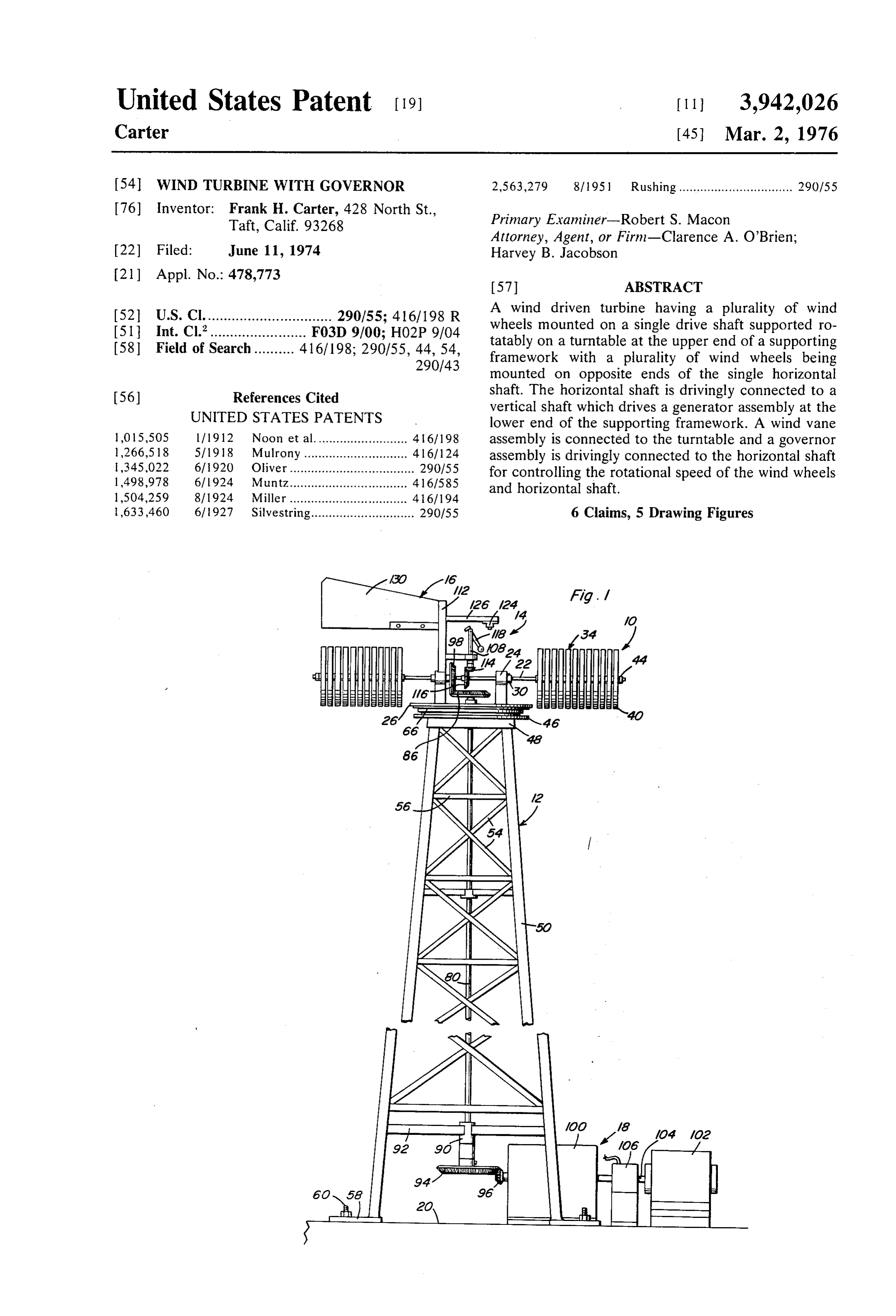
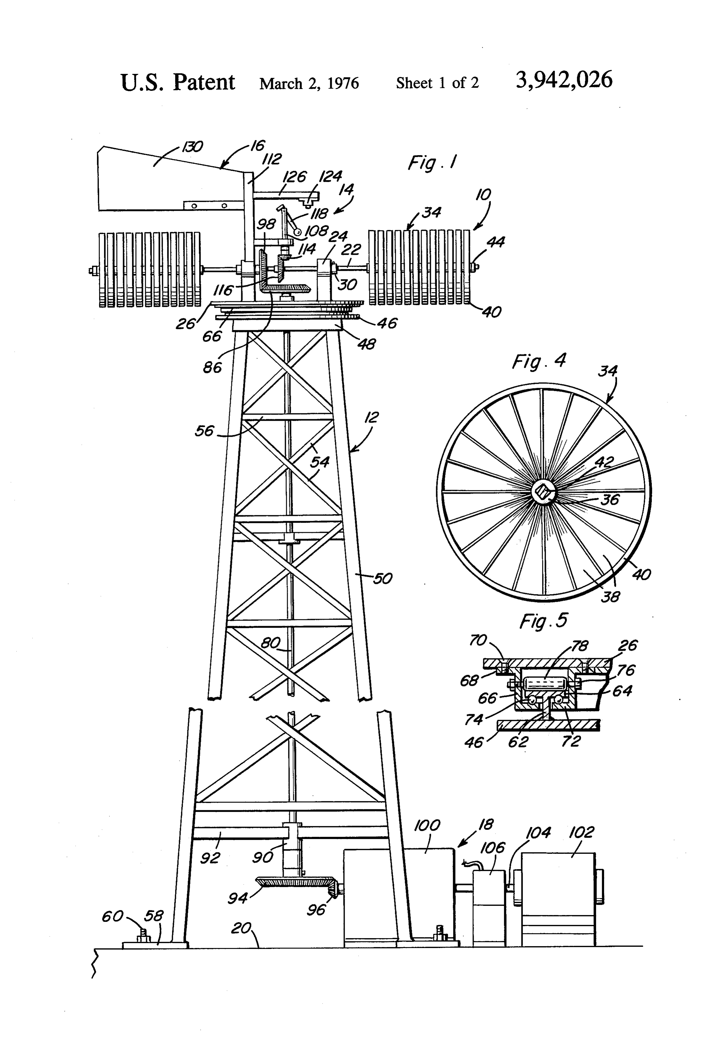
structure broken away indicating an indeterminate
WIND TURBINE WITH GOVERNOR height for the device.
BACKGROUND OF THE INVENTION
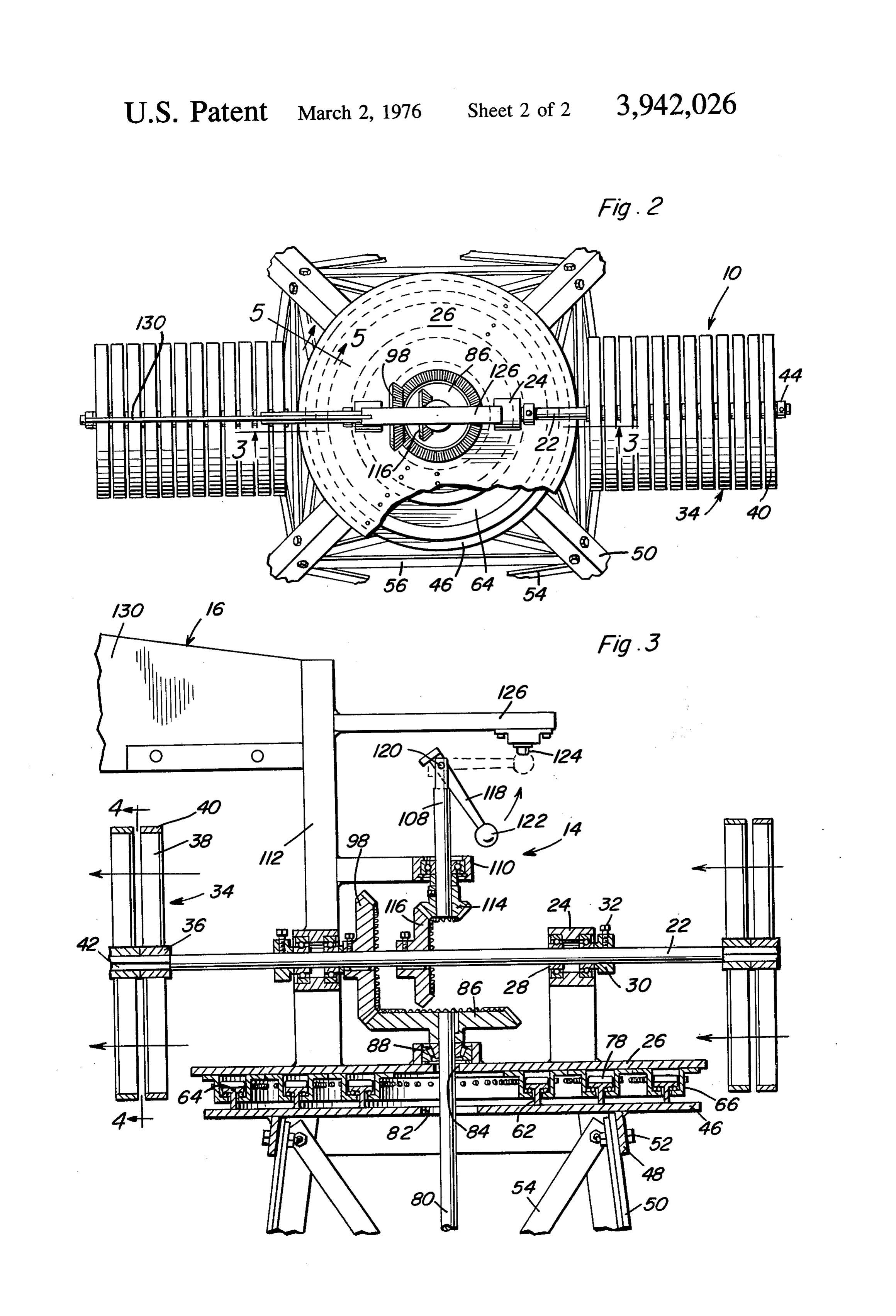
FIG. 2 is a top plan view of the construction of FIG.
1. Field of the Invention FIG. 3 is a vertical, sectional view, on an enlarged The present invention generally relates to a wind scale, taken substantially upon a plane passing along driven turbine assembly for driving a generator or gen section line 3-3 of FIG. 2 illustrating the structural erators in a manner to produce electrical energy in details of the invention.
response to rotation of the wind turbine and more par FIG. 4 is a vertical sectional view taken substantially ticularly to such an arrangement incorporating a novel 10 upon a plane passing along section line 4-4 of FIG. 3 turntable assembly for supporting the wind turbine illustrating the construction of one of the wind wheels. assembly from a supporting framework or derrick and FIG. 5 is a fragmental, sectional view, on an enlarged a governor for controlling rotational speed of the multi scale, taken substantially upon a plane passing along ple wind wheels. section line 5-5 of FIG. 2 illustrating further structural 15 details of the turntable structure.
2. Description of the Prior Art
The following U.S. patents relate generally to this DESCRIPTION OF THE PREFERRED field of endeavor. EMBODIMENT Referring now specifically to the drawings, the wind 554, 138 Feb. 4, 1896 20 turbine assembly 10 of the present invention is 1,816,632 July 28, 1931 mounted in elevated relation to the ground surface of
2,273,084 Feb. 17, 1942 the like by a supporting framework or derrick generally
designated by numeral 12 and includes a governor assembly 14, a wind vane assembly 16 with the turbine 25 assembly driving a generator assembly 18 located at ground level or on a supporting platform 20 or the like.
SUMMARY OF THE INVENTION The wind turbine assembly 10 includes a single, rigid, horizontally disposed shaft 22 rotatably supported by a
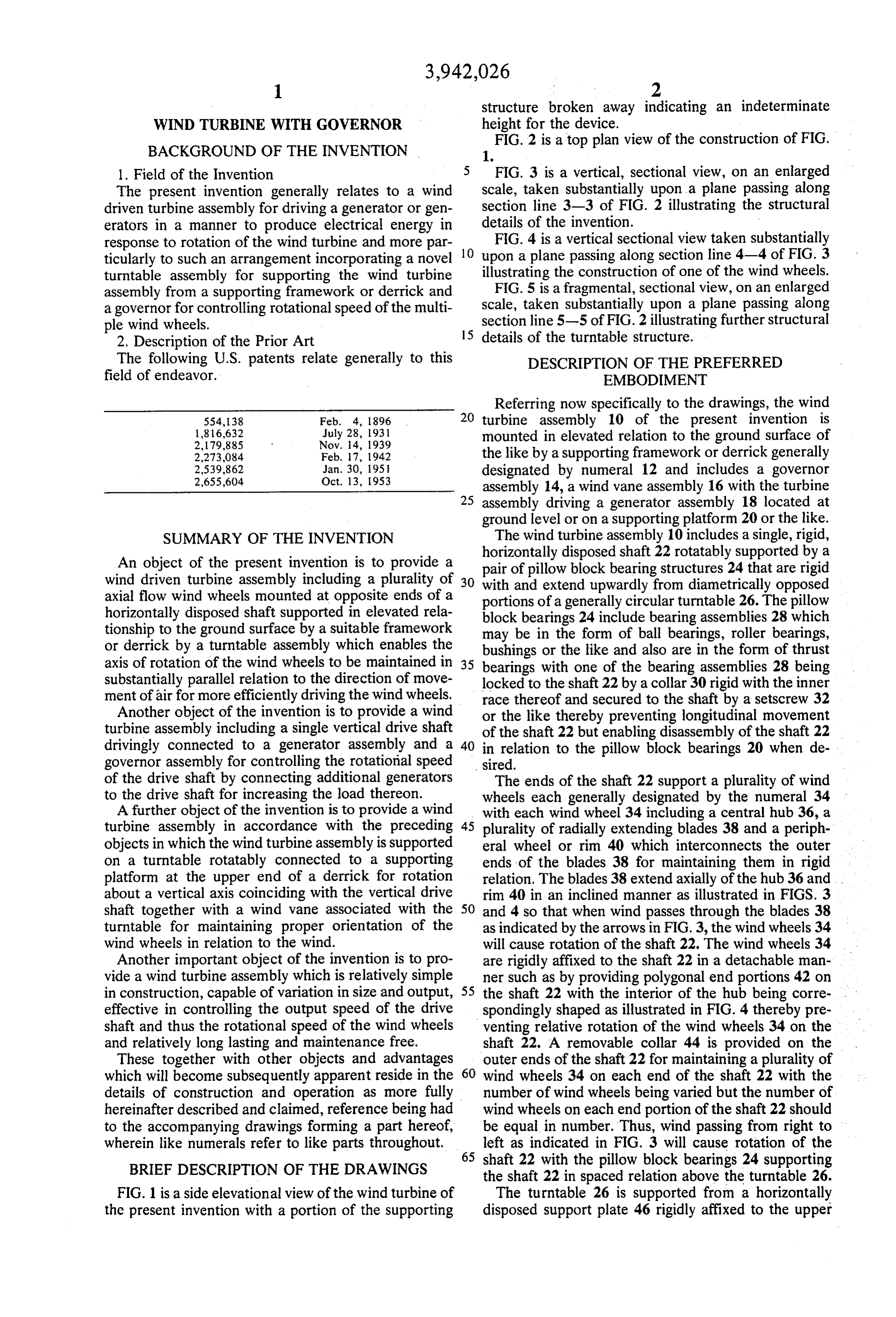
An object of the present invention is to provide a pair of pillow block bearing structures 24 that are rigid wind driven turbine assembly including a plurality of 30 with and extend upwardly from diametrically opposed axial flow wind wheels mounted at opposite ends of a portions of a generally circular turntable 26. The pillow horizontally disposed shaft supported in elevated rela block bearings 24 include bearing assemblies 28 which tionship to the ground surface by a suitable framework may be in the form of ball bearings, roller bearings, or derrick by a turntable assembly which enables the bushings or the like and also are in the form of thrust axis of rotation of the wind wheels to be maintained in 35 bearings with one of the bearing assemblies 28 being substantially parallel relation to the direction of move locked to the shaft 22 by a collar 30 rigid with the inner ment of air for more efficiently driving the wind wheels. race thereof and secured to the shaft by a setscrew 32 Another object of the invention is to provide a wind or the like thereby preventing longitudinal movement turbine assembly including a single vertical drive shaft of the shaft 22 but enabling disassembly of the shaft 22 drivingly connected to a generator assembly and a 40 in relation to the pillow block bearings 20 when de governor assembly for controlling the rotational speed sired.
of the drive shaft by connecting additional generators The ends of the shaft 22 support a plurality of wind to the drive shaft for increasing the load thereon. wheels each generally designated by the numeral 34 A further object of the invention is to provide a wind with each wind wheel 34 including a central hub 36, a turbine assembly in accordance with the preceding 45 plurality of radially extending blades 38 and a periph objects in which the wind turbine assembly is supported eral wheel or rim 40 which interconnects the outer on a turntable rotatably connected to a supporting ends of the blades 38 for maintaining them in rigid platform at the upper end of a derrick for rotation relation. The blades 38 extend axially of the hub 36 and about a vertical axis coinciding with the vertical drive rim 40 in an inclined manner as illustrated in FIGS. 3 shaft together with a wind vane associated with the 50 and 4 so that when wind passes through the blades 38 turntable for maintaining proper orientation of the as indicated by the arrows in FIG. 3, the wind wheels 34 wind wheels in relation to the wind. will cause rotation of the shaft 22. The wind wheels 34 Another important object of the invention is to pro are rigidly affixed to the shaft 22 in a detachable man vide a wind turbine assembly which is relatively simple ner such as by providing polygonal end portions 42 on in construction, capable of variation in size and output, 55 the shaft 22 with the interior of the hub being corre effective in controlling the output speed of the drive spondingly shaped as illustrated in FIG. 4 thereby pre shaft and thus the rotational speed of the wind wheels venting relative rotation of the wind wheels 34 on the and relatively long lasting and maintenance free. shaft 22. A removable collar 44 is provided on the These together with other objects and advantages outer ends of the shaft 22 for maintaining a plurality of which will become subsequently apparent reside in the 60 wind wheels 34 on each end of the shaft 22 with the details of construction and operation as more fully number of wind wheels being varied but the number of hereinafter described and claimed, reference being had wind wheels on each end portion of the shaft 22 should to the accompanying drawings forming a part hereof, be equal in number. Thus, wind passing from right to wherein like numerals refer to like parts throughout, 65 left as indicated in FIG. 3 will cause rotation of the BRIEF DESCRIPTION OF THE DRAWINGS shaft 22 with the pillow block bearings 24 supporting the shaft 22 in spaced relation above the turntable 26.
FIG. 1 is a side elevational view of the wind turbine of The turntable 26 is supported from a horizontally the present invention with a portion of the supporting disposed support plate 46 rigidly affixed to the upper
Page 5
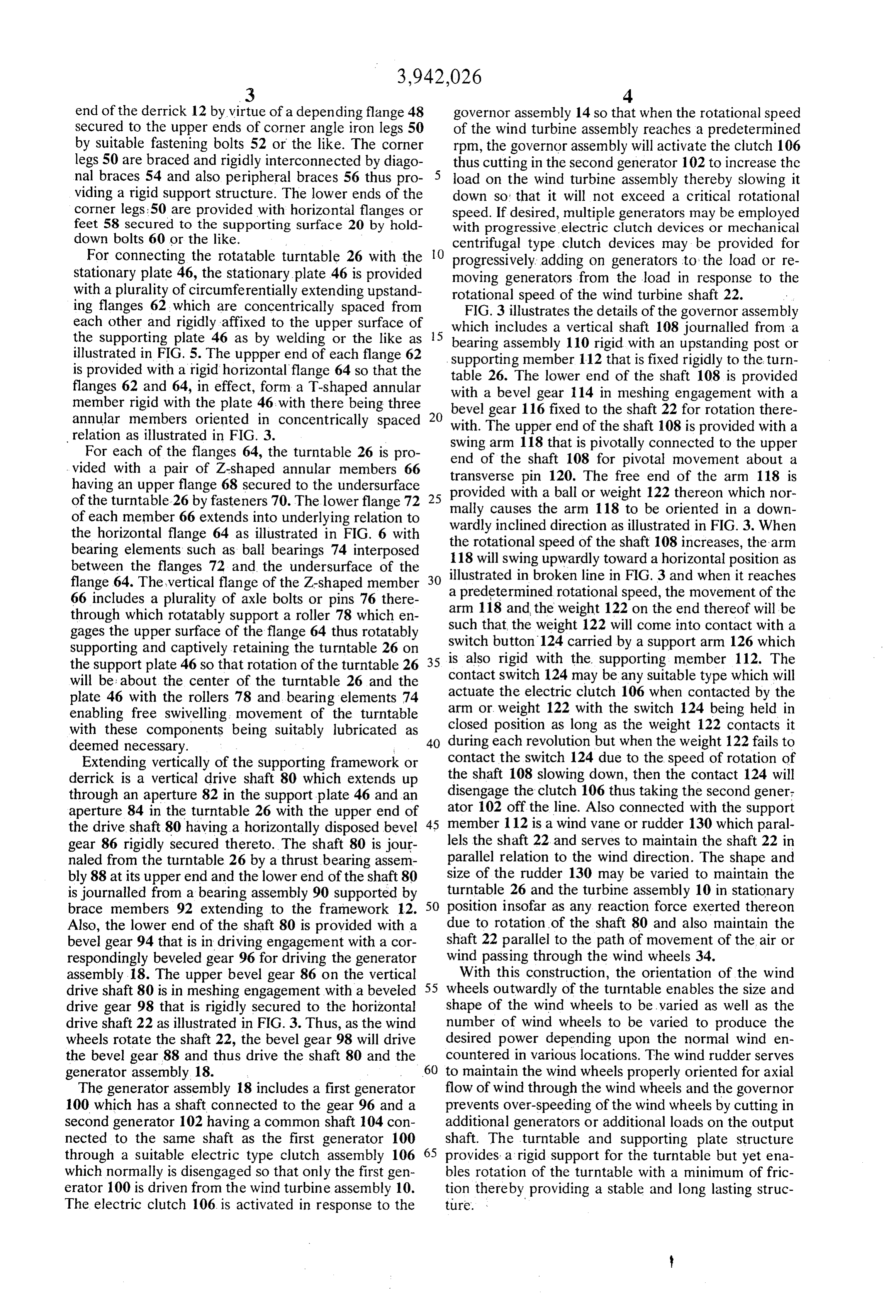
end of the derrick 12 by virtue of a depending flange 48 governor assembly 14 so that when the rotational speed Secured to the upper ends of corner angle iron legs 50 of the wind turbine assembly reaches a predetermined by suitable fastening bolts 52 or the like. The corner rpm, the governor assembly will activate the clutch 106 legs 50 are braced and rigidly interconnected by diago thus cutting in the second generator 102 to increase the nal braces 54 and also peripheral braces 56 thus pro load on the wind turbine assembly thereby slowing it viding a rigid support structure. The lower ends of the down so that it will not exceed a critical rotational corner legs:50 are provided with horizontal flanges orspeed. If desired, multiple generators may be employed feet 58 secured to the supporting surface 20 by hold with progressive electric clutch devices or mechanical down bolts 60 or the like. centrifugal type clutch devices may be provided for For connecting the rotatable turntable 26 with theO progressively adding on generators to the load or re
Stationary plate 46, the stationary plate 46 is provided moving generators from the load in response to the with a plurality of circumferentially extending upstand rotational speed of the wind turbine shaft 22. ing flanges 62, which are concentrically spaced from FIG. 3 illustrates the details of the governor assembly each other and rigidly affixed to the upper surface of 5 which includes a vertical shaft 108 journalled from a the supporting plate 46 as by welding or the like as bearing assembly 110 rigid with an upstanding post or illustrated in FIG. 5. The uppper end of each flange 62 is provided with a rigid horizontal flange 64 so that the supporting table 26.
member 112 that is fixed rigidly to the turn
The lower end of the shaft 108 is provided flanges 62 and 64, in effect, form a T-shaped annular with a bevel gear member rigid with the plate 46 with there being three 20 bevel gear 116 fixed114to inthemeshing engagement with a annular members oriented in concentrically spaced with. The upper end of the shaft 108for shaft 22
rotation there provided with a relation as illustrated in FIG. 3. Swing arm 118 that is pivotally connected to the upper For each of the flanges 64, the turntable 26 is pro end of the shaft 108 for pivotal movement about vided with a pair of Z-shaped annular members 66 transverse pin 120. The free end of the arm 118 isa having an upper flange 68 secured to the undersurface provided with a ball or weight 122 thereon which nor of the turntable 26 by fasteners 70. The lower flange 72 25 mally of each member 66 extends into underlying relation to wardlycauses the arm 118 to be oriented in a down inclined direction as illustrated in FIG. 3. When the horizontal flange 64 as illustrated in FIG. 6 with the rotational speed of the shaft 108 increases, the arm bearing elements such as ball bearings 74 interposed 118 will swing upwardly between the flanges 72 and the undersurface of the 30 illustrated in broken linetoward a horizontal position as in FIG. 3 and when it reaches flange 64. The vertical flange of the Z-shaped member a predetermined rotational speed, the movement of the 66 includes a plurality of axle bolts or pins 76 there arm 118 and the weight 122 on the end thereof will be through which rotatably support a roller 78 which en such that the weight 122 will come into contact with a gages the upper surface of the flange 64 thus rotatably
Supporting and captively retaining the turntable 26 on Switch button 124 carried by a support arm 126 which the support plate 46 so that rotation of the turntable 26 35 is also rigid with the supporting member 112. The will be: about the center of the turntable 26 and the contact switch 124 may be any suitable type which will plate 46 with the rollers 78 and bearing elements 74 actuate arm or the electric clutch 106 when contacted by the weight 122 with the switch 124 being held in enabling free swivelling movement of the turntable with these components being suitably lubricated as closed position as long as the weight 122 contacts it deemed necessary. 40 during each revolution but when the weight 122 fails to Extending vertically of the supporting framework or contact the switch 124 due to the speed of rotation of derrick is a vertical drive shaft 80 which extends up the shaft 108 slowing down, then the contact 124 will through an aperture 82 in the support plate 46 and an disengage the clutch 106 thus taking the second gener. aperture 84 in the turntable 26 with the upper end of ator 102 off the line. Also connected with the support the drive shaft 80 having a horizontally disposed bevel 45 member 112 is a wind vane or rudder 130 which paral gear 86 rigidly secured thereto. The shaft 80 is jour lels the shaft 22 and serves to maintain the shaft 22 in naled from the turntable 26 by a thrust bearing assem parallel relation to the wind direction. The shape and bly 88 at its upper end and the lower end of the shaft 80 size of the rudder 130 may be varied to maintain the is journalled from a bearing assembly 90 supported by turntable 26 and the turbine assembly 10 in stationary brace members 92 extending to the framework 12. 50 position insofar as any reaction force exerted thereon Also, the lower end of the shaft 80 is provided with a due to rotation of the shaft 80 and also maintain the bevel gear 94 that is in driving engagement with a cor shaft 22 parallel to the path of movement of the air or respondingly beveled gear 96 for driving the generator wind passing through the wind wheels 34. assembly 18. The upper bevel gear 86 on the vertical With this construction, the orientation of the wind drive shaft 80 is in meshing engagement with a beveled 55 wheels outwardly of the turntable enables the size and drive gear 98 that is rigidly secured to the horizontal shape of the wind wheels to be varied as well as the drive shaft 22 as illustrated in FIG. 3. Thus, as the wind number of wind wheels to be varied to produce the wheels rotate the shaft 22, the bevel gear 98 will drive desired power depending upon the normal wind en the bevel gear 88 and thus drive the shaft 80 and the countered in various locations. The wind rudder serves generator assembly 18. 60 to maintain the wind wheels properly oriented for axial The generator assembly 18 includes a first generator flow of wind through the wind wheels and the governor 100 which has a shaft connected to the gear 96 and a prevents over-speeding of the wind wheels by cutting in Second generator 102 having a common shaft 104 con additional generators or additional loads on the output nected to the same shaft as the first generator 100 shaft. The turntable and supporting plate structure through a suitable electric type clutch assembly 106 65 provides a rigid support for the turntable but yet ena which normally is disengaged so that only the first gen bles rotation of the turntable with a minimum of fric erator 100 is driven from the wind turbine assembly 10. tion thereby providing a stable and long lasting struc The electric clutch 106 is activated in response to the ture. .
Page 6
S 6
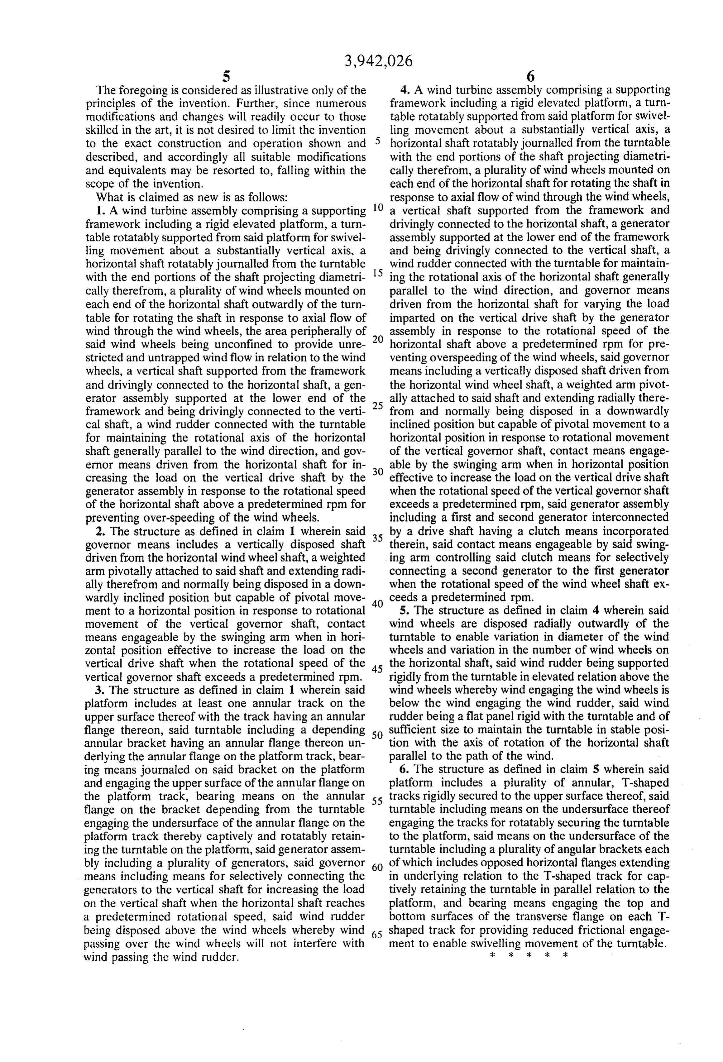
The foregoing is considered as illustrative only of the 4. A wind turbine assembly comprising a supporting principles of the invention. Further, since numerous framework including a rigid elevated platform, a turn modifications and changes will readily occur to those table rotatably supported from said platform for swivel skilled in the art, it is not desired to limit the invention ling movement about a substantially vertical axis, a to the exact construction and operation shown and horizontal shaft rotatably journalled from the turntable described, and accordingly all suitable modifications with the end portions of the shaft projecting diametri and equivalents may be resorted to, falling within the cally therefrom, a plurality of wind wheels mounted on scope of the invention. each end of the horizontal shaft for rotating the shaft in What is claimed as new is as follows: response to axial flow of wind through the wind wheels, 1. A wind turbine assembly comprising a supporting 10 a vertical shaft supported from the framework and framework including a rigid elevated platform, a turn drivingly connected to the horizontal shaft, a generator table rotatably supported from said platform for swivel assembly supported at the lower end of the framework ling movement about a substantially vertical axis, a and being drivingly connected to the vertical shaft, a horizontal shaft rotatably journalled from the turntable wind rudder connected with the turntable for maintain with the end portions of the shaft projecting diametri 15 ing the rotational axis of the horizontal shaft generally cally therefrom, a plurality of wind wheels mounted on parallel to the wind direction, and governor means each end of the horizontal shaft outwardly of the turn driven from the horizontal shaft for varying the load table for rotating the shaft in response to axial flow of imparted on the vertical drive shaft by the generator wind through the wind wheels, the area peripherally of 20 assembly in response to the rotational speed of the said wind wheels being unconfined to provide unre horizontal shaft above a predetermined rpm for pre stricted and untrapped wind flow in relation to the wind venting overspeeding of the wind wheels, said governor wheels, a vertical shaft supported from the framework means including a vertically disposed shaft driven from and drivingly connected to the horizontal shaft, a gen the horizontal wind wheel shaft, a weighted arm pivot erator assembly supported at the lower end of the 25 ally attached to said shaft and extending radially there framework and being drivingly connected to the verti from and normally being disposed in a downwardly cal shaft, a wind rudder connected with the turntable inclined position but capable of pivotal movement to a for maintaining the rotational axis of the horizontal horizontal position in response to rotational movement shaft generally parallel to the wind direction, and gov of the vertical governor shaft, contact means engage ernor means driven from the horizontal shaft for in 30 able by the swinging arm when in horizontal position creasing the load on the vertical drive shaft by the effective to increase the load on the vertical drive shaft generator assembly in response to the rotational speed when the rotational speed of the vertical governor shaft of the horizontal shaft above a predetermined rpm for exceeds a predetermined rpm, said generator assembly preventing over-speeding of the wind wheels. including a first and second generator interconnected 2. The structure as defined in claim 1 wherein said 35 by a drive shaft having a clutch means incorporated governor means includes a vertically disposed shaft therein, said contact means engageable by said swing driven from the horizontal wind wheel shaft, a weighted ing arm controlling said clutch means for selectively arm pivotally attached to said shaft and extending radi connecting a second generator to the first generator ally therefrom and normally being disposed in a down when the rotational speed of the wind wheel shaft ex wardly inclined position but capable of pivotal move 40 ceeds a predetermined rpm.
ment to a horizontal position in response to rotational 5. The structure as defined in claim 4 wherein said movement of the vertical governor shaft, contact wind wheels are disposed radially outwardly of the means engageable by the swinging arm when in hori turntable to enable variation in diameter of the wind zontal position effective to increase the load on the wheels and variation in the number of wind wheels on vertical drive shaft when the rotational speed of the 45 the horizontal shaft, said wind rudder being supported vertical governor shaft exceeds a predetermined rpm. rigidly from the turntable in elevated relation above the 3. The structure as defined in claim 1 wherein said wind wheels whereby wind engaging the wind wheels is platform includes at least one annular track on the below the wind engaging the wind rudder, said wind upper surface thereof with the track having an annular rudder being a flat panel rigid with the turntable and of flange thereon, said turntable including a depending 50 sufficient size to maintain the turntable in stable posi annular bracket having an annular flange thereon un tion with the axis of rotation of the horizontal shaft derlying the annular flange on the platform track, bear parallel to the path of the wind. ing means journaled on said bracket on the platform 6. The structure as defined in claim 5 wherein said and engaging the upper surface of the annular flange on platform includes a plurality of annular, T-shaped the platform track, bearing means on the annular 55 tracks rigidly secured to the upper surface thereof, said flange on the bracket depending from the turntable turntable including means on the undersurface thereof engaging the undersurface of the annular flange on the engaging the tracks for rotatably securing the turntable platform track thereby captively and rotatably retain to the platform, said means on the undersurface of the ing the turntable on the platform, said generator assem turntable including a plurality of angular brackets each bly including a plurality of generators, said governor 60 of which includes opposed horizontal flanges extending means including means for selectively connecting the in underlying relation to the T-shaped track for cap generators to the vertical shaft for increasing the load tively retaining the turntable in parallel relation to the on the vertical shaft when the horizontal shaft reaches platform, and bearing means engaging the top and a predetermined rotational speed, said wind rudder bottom surfaces of the transverse flange on each T being disposed above the wind wheels whereby wind shaped track for providing reduced frictional engage passing over the wind wheels will not interfere with ment to enable swivelling movement of the turntable. wind passing the wind rudder. :k : : k sk
Provenance
- Collection
- Cited prior art
- Original PDF
- patentimages.storage.googleapis.com →
- Filed
- 1974-06-11
- Pages
- 6
- Method
- pdftotext (the PDF's own text layer) + pdftoppm 300dpi page scans
- Source
- Google Patents bibliographic record
- Granted
- 1976-03-02
- Inventors
- Frank H. Carter
- Transcribed from
- patentimages.storage.googleapis.com →