patent · US1894357
Wind electric plant
17 January 1933
Page 1
Drawing sheet — no readable text.
Page 2
Drawing sheet — no readable text.
Page 3
Patented Jan. 17, 1933 1894,357
UNITED STATES PATENT OFFICE
GEORGE MANIKOWSKE, OF MINNEAPOLIS, MINNESOTA, AND GEORGE FENEIS AND
WALLACE MANIKOWSKE, OF MOORETON, NORTH DAKOTA, ASSIGNORs, BY DIRECT
AND MESNE ASSIGNMENTS, TO ETHEL PURDON MANIKows KE, OF MINNEAPOLIS,
NNESOA
wIND ELECTRIC PLANT
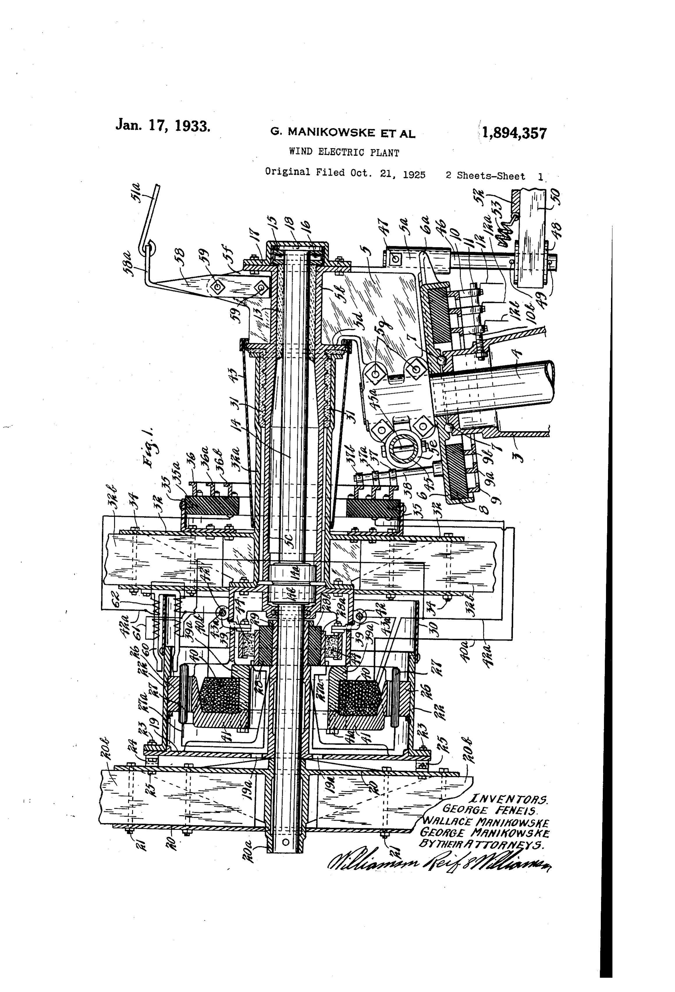
Application fled October 21, 1925, Serial No. 64062. Renewed October 9, 1931. This invention relates to a wind electric each other under certain conditions and to plant. Such plants are used comprising air Swing the propellers away from the wind. propellers adapted to be operated by the wind These and other objects and advantages of which have combined therewith the revoluble the invention will be fully set forth in the parts of an electric generator. Such plants following description made in connection 55 are now commonly used to supply current for with the accompanying drawings in which Small establishments, such as farms, resorts, like reference characters refer to the same garages, etc., and to charge storage batteries parts throughout the different views, and in
It is an object of this invention to provide Fig. 1 is a central vertical section through 90 a very simple and efficient wind electric the device and the top of the tower carrying plant comprising a pair of oppositely rotat the same, the outer ends of the propellers be ing airdriven propellers which, respectively, ing broken away and the controlling means carry the 5 generator.
rotating parts of an electric current being, in part, broken away; and
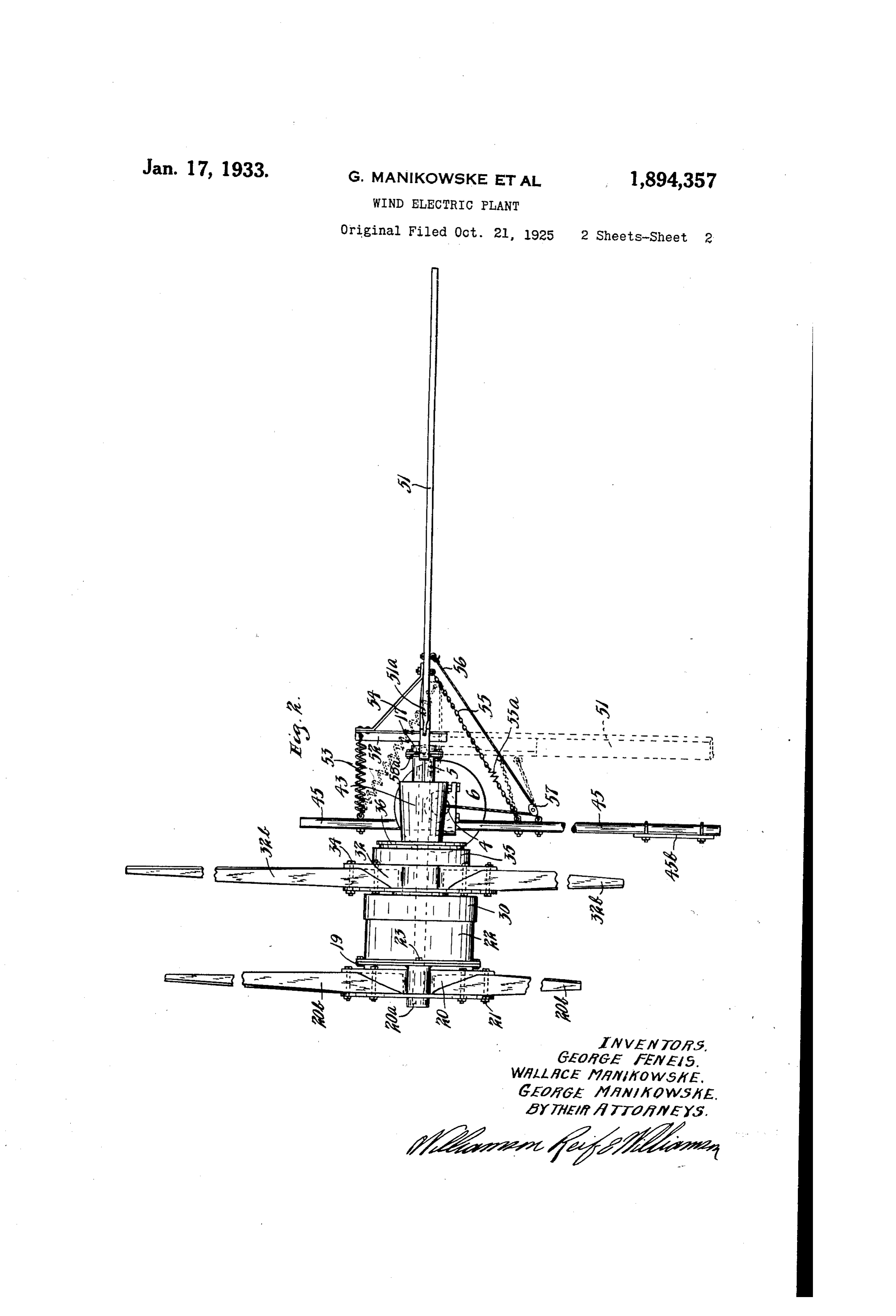
Fig. 2 is a top plan view of the device show 65
It is another object of the invention to pro ing the gontrolling means, and a different po vide such an electric plant as set forth in the sition of certain parts in dotted lines. preceding paragraphin which the propellers Referring to the drawings, the upper por tion of a tower column or support 3 is shown 20 are co-axial, one carried by a sleeve which ro which preferably will receive a central shaft 70 tates on a crank on which the other propellerisjournaled.
the shaft carrying 4. The axes of support 3 and shaft 4 nor
It is still another object of the invention. mally are preferably vertical. The frame to provide a wind electric plant comprising member 5 is secured to the top of shaft 4 by 25 Oppositely rotating air driven coaxially ar. means of headed and nutted bolts 5g passing ranged propellers, one of which rotates afield through split portions thereof which por 75 and the other of which rotates an armature tions clamp the shaft. The frame 5 rests arranged concentrically with said field. upon a ring or disk 6 having a ball bearing It is still another object of the invention to race on its underside in which travel the balls provide a wind electric plant, as set forth in also running in a race in the top of the col 80 30 th?, preceding paragraph in which the pro umn 3. The ring or disk 6 surrounds the peller rotating the field also carries brushes shaft 4 and has secured therein insulating cooperating with a commutator rotated by the material 8 on which are secured a plurality other propeller, suitable conductors and col of collecting rings 9,9a and 9b, respectively. lecting rings being provided for taking off A plurality of brushes 10,10a and 10b co 35 the current. operate, respectively, with the rings 9,9a and It i? a further object of the invention to 9b and are carried on the member 11 threaded proyide Sucha windelectric plant, as defined into and secured by a clamping nut in the in the preceding paragraphs, which is rotat column 3 to which brushes are connected the ably mounted on a support and which carries conductors. 12, 12a, and 12b, respectively. 40 controlling means adapted to swing the pro
The ring 6 has a fork (a projecting at one pellers away from the wind when a certain side which embraces a hub. 5 at one lower torque the or a certain speed has been reached by corner of frame 5 so that frame 5 and ring 6 propellers. rotate together. The frame 5 has a bearing It is a still further object of the invention 45 to provide such a wind electric plant, as de 5b at its upper end having suitable antifric tion material 13 therein in which is jour 05 fined in the preceding paragraph in which naled a shaft 14. This shaft is held from the controlling means comprises a pair of endwise movement in one direction by a col vanes, one of which is normally disposed at lar 15 secured thereto by a pin 16, said collar right angles to the axis, of the propellers, and pin being enclosed by a cap member 17 50 said vanes being arranged to move toward secured tightly to the end of frame 5 where
Page 4
by an oiling chamber may be formed in the and 37 b to the rings 9,9a and 9b, respectively. cap 17. Said cap may be lined on its cylin The end of sleeve 32a opposite bearing 5b drical wall with suitable antifriction ma has a circumferential flange projecting there terial 18 forming a bearing for the collar 15. from to which is secured by suitable circum The bearing 5b projects at the side opposite ferentially spaced headed and nutted bolts, 70 cap 17 to form a long tube 5c, said tube being a shell 39. This shell has a frame portion bored in its outer end to receive the outer 39a, at its outer end which carries the field shell of a ball bearing, the inner shell or coils 40, said frame being of rather heavy casing of which is carried by shaft 14. The cross section and having a heavy pole piece O shaft 14, at its outer end, has secured thereto 41 secured thereto by the circumferentially 5 the central hub of a member 19 and outward spaced screws 41a. It will be noted that the of the member 19 the shaft has secured there outer periphery of piece 41 is concentric with to a central hub 20a of a propeller frame 20. the armature members 26 and 27 and rotates The blades 205 of the propeller are secured in close proximity thereto. The shell 39 also 15 in the frame 20 by the headed and nutted has mounted thereon a rotatable brush hold 80 bolts 21. The blades 205 will be of thin heli ing framehaving lugs 42 in whichiare se cal form such as commonly used on air cured the brush holders 43a carrying the driven propellers. The frame 19 has a drum brushes 44 which are concentric with and in 22 bolted thereto by the headed and nutted engagement with the armature 28. The 20 bolts 23 passing through a cylindrical flange shell 39 has a hub bored to receive the outer 85 at one end of said drum and said bolts also shell 14b of a ball bearing, the inner shell preferably pass through flexible straps 24 of which is carried by shaft 14. There will, which are also bolted to member 19 and are of course, be suitable balls or other anti-fric attached at their other ends by headed and tion members between the rings 14a and 14b 25 nutted bolts 25 to the propeller frame 20. and the inner rings carried by shaft 14. A 90 The drum 22 has secured in its inner side an casing 43 is secured at one of its ends to the armature or frame 26 in which are wound the flange 5d and extends over the sleeve 32a. armature or armature coils 27. The hub of The brush holders 43a will be connected member 19 at its inner end carries a commu by suitable conductors 42a to the rings 36 and 30 tator 28 comprising the usual bars 28a sepa 360, respectively. The ring 36a is connected 95 rated by the insulation members 28b, this by a suitable conductor 40a to one end of the commutator being fitted on a reduced portion field windings 40. The other end of said of the hub of member 19 against tile shoulder field windings are connected by a suitable formed by said reduced portion and being conductor 40b to one of the brush holders 43a. 35 held thereon by a collar 29 threaded on the The armature winding 27 is connected by 100 end of said hub. An enclosing shell 30 is suitable conductors 27 a to the commutator 28. secured to the open end of drum 22 and en While the generator may be of any desired closes the commutator and adjacent parts. type, with the connections and parts shown The tube 50 carries at one end a member it is of a direct current type being compound 40 31 of suitable antifriction material and the wound. 105 hub or sleeve 32a of a propeller frame 32 is The propeller frame 32 has secured at its journaled at one end on said member 31. rear side one or more U-shaped members 60 The sleeve 32a, has an annular collar at one forming the pole pieces for an electro-mag end which abuts against a flange formed on net. These pole pieces, as shown in Fig. 1, O 45 the member 31, thus forming a thrust bearing are disposed at each side of the shell 30 and and the flange on member 31 abuts against a drum 22. Each of said pole pieces is pro flange 5d formed about the bearing 5b. The vided with a shunt winding 61 leading from propeller frame 32 has secured therein the the conductors 42a and each of said pole ends of the propeller blades 32b which are pieces is also provided with a series winding 5 50 fastened by the headed and nutted bolts 34. 62 formed by the conductors 42a, the series The propeller blades 32a will be of the ordi winding being disposed on said pole pieces nary helical type used for air driven pro so as to counteract the magnetic effect pro pellers but will be disposed so as to be ro duced by the shunt windings 61. tated in the opposite direction to the blades The frame 5 has a cylindrical hollow lug 55 20b. The propeller frame 32 has secured 5e at one side in which is secured an arm 45 120 thereto at the side adjacent bearing 5b, by shown as held by the headed and nutted bolts suitable headed and nutted bolts, a flanged 45a passing through lug 5e and which is ring 35 having a ring of insulating material shown as a pipe or tube. This arm 45 pro 35a, secured therein on which are mounted jects at either side of the shaft 4 and it will 60 collector rings 36, 36a and 36b. Brushes 37, be seen that it is a short distance at one side 37a and 37b engage, respectively, the rings of said shaft. Said arm 45 is disposed sub 36,36a and 36b, said brushes being carried stantially at right angles to the axis of shaft by the member 38 secured to a hub projecting 14 and carries at one end a vane 45b which is from the ring 6 through which pass suitable disposed beyond the outer ends of the pro 65 conductors connecting the brushes 37, 37a. peller blades 20b and 32b and in a plane sub 30
Page 5
stantially normal to the axis of the propellers purpose the conductor 12a is connected to the formed by said blades. The hub 5a on frame field coil. The generator will be under load 5 has secured therein a short shaft 46 shown and a certain torque will be developed by as held by a headed and nutted bolt 47 pass the rotating propellers. This torque causes ing therethrough and through the hub 5a. A a corresponding, thrust or pressure of the collar 48 is journaled on shaft 46 being held wind against the propellers creating a mo from movement lengthwise of said shaft by ment arm which tends to revolve the pro suitable members, such as the pins 49 at each pellers and frame clockwise about the axis side thereof. An arm 50 is secured to the of shaft 4. This tendency to rotate about O collar 48 and projects outwardly therefrom the axis of shaft 4 will be resisted by the away from the shaft 4 substantially in line pressure of the wind against vane 45b which with the axis of shaft 14. Attention is called creates a moment arm tending to rotate frame to the fact that the axis of shaft 14 is dis 5 about axis 4 in the opposite direction. posed some distance to one side of the axis of When the generator is under full load the 5 shaft 4, as clearly shown in Fig. 2. The arm propellers will have reached a certain speed 80 50 has secured at its outer side a large vane and vane 45b will then just balance the torque 51. A bar 52, illustrated as an angle bar, is or force on the propellers so that the pro secured to arm 50 and projects substantially pellers will be held in the wind or with their at right angles thereto having its outer end axes parallel with the direction of the wind. 20 connected by the tensile coiled spring 53 to If the wind increases or is strong enough 85 one end of arm 45. A brace 54 is also shown to cause the propellers to run above this extending from the outer end of bar 52 to speed more air will pass through the pro the vane 51 carried on arm 50. The vane 51 pellers and the moment arm caused by pres is also connected by a flexible member, such sure of the wind on vane 45b will overbal 25 as a chain 55 to the arm 45 at some distance ance the moment arm urging the propellers 90 from the shaft 4 and at the opposite side to swing clockwise about shaft 4 and vane thereof from the spring 53 a spring 55a pref 45b will swing and approach vane 51, the erably being inserted in said chain. The latter extending spring 53. The vanes will vane 51 also has secured thereto a flexible thus approach each other and if the wind is 30 member, such as a cable or rope 56 which ex sufficientlystrong will eventually come into tends over a pulley in the pulley block 57 se parallel relation, as indicated in dotted lines cured to arm 45 somewhat outward of the in Fig. 2. When this occurs, the vanes 45b end of chain 55 and which end extends to and 51 will, of course, be maintained with ward shaft 4 and downward therein. Said their planes parallel with the direction of 35 cable will be guided by suitable pulleys (not the wind and the propellers will be swung 100 shown) and will extend down in shaft 4 and outthe of the wind or with their axes at an angle tower 3 to a point convenient for manipula to are direction of the wind. The propellers thus effectively controlled so that they tion by the operator. The top of vane 51 has will not run above a certain speed and the an arm 51a projecting therefrom having an 40 eyelet or loop at its end loosely engaged in load torque exerted cannot run above a cer 05 an aperture formed in the end 58a of a cally tain point. The propellers will automati bracket 58 bolted to a web.5f in the top of will bebeseen governed, according to the load. It that vane 51, when it moves from frame 5 by headed and nutted bolts 59. It normal will be seen that the portion 58a of arm 58 since its position, moves into a higher plane axis is inclined to the vertical. This 10 is bent substantially at right angles. The vane would tend to return to normal posi aperture in portion 58a is substantially in axial alinement with the shaft 46 and it will tion by gravity. The spring 53, however, be seen that since shaft 4 is vertical its axis is provided to insure that the parts will re is inclined to the vertical extending toward turn 50 the axis of shaft 4 at its lower end.
to normal position upon a reduction of speed of the propellers or reduction of wind I5
In operation, when the plant is running, framethrust against the same. It will be seen that the propellers comprising blades 20b and 32b, to 5 will move easily on column 3, owing respectively, will be driven in opposite di ported on amoving the same with ring 6 which is sup ball bearing. The flexible con rections by the wind. The armature 27 will
thus be rotated by one propeller and the field nection, including members 25 between the 20 40 by the other propeller and in opposite so that thisframe propeller frame and members 19, is provided may be disconnected from directions. Electromotive-force will thus be the propellers under certain testing opera generated and the current will be taken off of tions. The parts adjacent shaft 14 are all
commutator 28 by the brushes 44 and de nicely enclosed by drum 22 and casing 30 livered to the rings 36 and 36b, respectively, and the generator parts will be effectively from which it will be conducted to rings 9 cooled by the air passing thereover, air holes and 9b, respectively and to the conductors 19a, being provided in member 19 for this 12 and 12b, respectively. A regulator will purpose. Cable 56 is provided so that the be ordinarily used to regulate the field cur vanes can manually be brought together, thus. 30 rent, which regulator is not shown. For this swinging the propellers away from the wind.
Page 6
Chain 55 limits the separating movement of first mentioned propeller, a field adjacent said the vanes. ? armature rotated by said second propeller, a The electro-magnets 60 embrace the shell 30 magnet driven by said second propeller hav and are also provided to insure that the pro ing pole pieces at each side of said shell and pellers will not be driven at too high a speed conductors for taking off the current gen 70 when the load is off of the generator or plant. erated by said field and armature, each of When there is no load on the generator there said pole pieces having a series winding will be practically no current flowing in the thereon of said conductors, and a shunt wind line or in conductors 42a so that practically ing thereof from said conductors adapted to 0 no magnetic effect will be produced by the neutralize the magnetic effect of said series 75 series windings 62 in the magnet member winding whereby when no load is on said 60. The shunt winding 61, however, which generator a braking effect will be produced will have a high resistance, will have a cur on said shell and said propeller. rent flowing therein and will produce a strong 2. A wind electric plant having in combi 5 magnetic field about the pole pieces of mem nation, a frame, a shaft journaled therein, a 80 ber 60. The shell 30 which rotates through flanged disk carried by said shaft, an insulat this field will be made of some such metal as ing member in said disk, spaced collector aluminum or copper and a braking effect will rings carried by said insulating member, a thus be produced on the shell and corre plurality of brushes carried by said frame 20 spondingly, on the magnet 60. This braking effect will be increased with the speed of the engaging said collector rings, conductors con 85 nected to said brushes, a member extending propellers so that they will be retarded and upwardly will be kept from running away or revolving of brushesfrom said disk having a plurality carried thereby, a bracket revo at too high a speed. When a load is placed luble with said shaft and disk, a shaft jour 90 25 on the generator and current flows through the series winding 62, the magnetic effect of naled in said bracket, a hollow shaft sur rounding said shaft and journaled on said the magnets 60 will be practically eliminated bracket and no braking effect will occur. The brak flanged disk having a flange thereon, a second ing effectis, therefore, automaticallyy put on sulating member connected to said flange, an in carried by said last men 30 the propellers when the load is off of the gen tioned flanged disk, a plurality of spaced col 95 erator and the propellers are running idle. lector rings carried on said last mentioned in The shaft 14 extends upwardly toward the propellers so that an oil reservoir may be sulating by said member and engaged respectively last mentioned brushes, means for formed in tube 56 and sleeve 32a and the oil generating electric current carried by said 00 35 will run toward this reservoir in shaft 14 shafts and conductors so that oil is kept away from the generator means to said last mentioned extending from said parts. collector rings. One of the great advantages of applicant's bination, a frame, a shaft journaledinin com 3. A wind electric plant having said structure is that owing to the oppositely ro frame and extending substantially vertical 40 tating propellers a balanced structure is ob ly, a bracket secured to said shaft, a shaft tained and it is possible to secure a delicate extending and efficient control. substantially at right angles to said first mentioned
From the above description it is seen that bracket, a propeller secured shaft journaled in said applicant has provided a very compact, of said last mentioned shaft,adjacent a hollow one end shaft 10 45 simple and efficient wind electric plant. The journaled on said bracket surrounding parts are comparatively few and simply con second mentioned shaft and concentric there said structed and the machine is arranged for very with, a propeller carried by said hollow shaft, efficient automatic control. The device has and been amply demonstrated in actual practice ly byansaid 50 and fou armature and field carried respective hollow shaft and said second men 5 to be very successful and efficient. tioned shaft and disposed between said pro It will, of course, be understood, that vari pellers.
ous changes may be made in the form, details, 4. A wind electric plant having in combi arrangement and proportions of the parts nation, a frame, a substantially vertical shaft Without departing from the scope of appli 55 cants, invention, which, generally stated, journaled therein and projecting thereabove, 120 consists in a device capable of carrying out ashaft bracket secured to the projecting end of said the objects above set forth, in the novel parts naled having a bearing therein, a shaft jour in said bearing extending substantially and combinations of parts disclosed and de at right angles to said first mentioned shaft, fined in the appended claims. a thrust bearing carried by said bearing en 60 What is claimed is: gaged by one end of said shaft, a propeller 1. A wind electric plant having in combi carried by the opposite end of said shaft, an nation, an air-driven propeller, an armature armature carried by said shaft between its rotatable thereby, a shell driven by said pro ends, a hollow shaft journaled on said
peller, a second air-driven propeller adapted bracket, said bracket having a thrust bearing to be rotated in a direction opposite to the engaged by one end of said hollow shaft, a 130
Page 7
propeller carried by said hollow shaft, and to rotate in a direction opposite to said first a field carried by said hollow shaft disposed mentioned propeller, a frame secured to one within said armature. of Said propellers, a field winding on said 5. A wind electric plant havingin combina last mentioned frame, said last mentioned tion a frame rotatable about a substantially. frame having spaced arms extending radial 0. vertical axis, a substantially horizontal ly, and then substantially horizontally over shaft journaled in said frame, a propeller said winding, and an armature secured to Secured to said shaft, a hollow shaft jour the other of said propellers and closely sur
nailed in said frame and surrounding said rounding said arms.
first mentioned shaft, a propeller carried by 9. A wind electric plant having in com 75 said hollow shaft and constructed and ar. bination, a column, a frame rotatable on said ranged to rotate in a direction opposite to column about a substantially vertical axis, said first mentioned propeller, a frame se a substantially horizontal shaft journaled cured to said last mentioned propeller hav 5 ing a cylindrical portion, a field winding on in said frame, a propeller secured to said 80 shaft, a second propeller rotatable about the
Said portion, said last mentioned frame hav axis of said shaft and constructed and ar ing spaced arms extending radially and then ranged to rotate in a direction opposite to substantially horizontally over said wind said first mentioned propeller, a field wind ing, a drum carried by said first mentioned ing carried by one of Said propellers, an ar propeller and an armature secured to the in mature carried by the other of said propellers 85 terior of said drum and closely surrounding and adapted to rotate close to said field wind said arms. ing, said field winding and armature being 6. A wind electric plant having in combi disposed between said propellers, collector 25 nation, a frame rotatable about a substan rings carried by one of said propellers and tially vertical axis, a substantially horizon brushes carried by said frame engaging said 90 tal shaft journaled insaid frame, a propeller rings respectively.
secured to said shaft, a hollow shaft sur 10. In a wind electric plant, a support or rounding said shaft and journaled in said standard, an upright shaft journaled there 30 frame, a second propeller secured to said hol in and projecting thereabove, a bracket se low shaft, a field winding carried by one of cured to the projecting end of said shaft and 95 said propellers, an armature carried by the having a bearing therein, a shaft journaled other of said propellers said field winding in said bearing and inclined somewhat from and armature being disposed between said
propellers, a flanged member at the rear of the horizontal, a ?????????? carried by the outer end of said shaft,9 a concentric sleeve 00 said second propeller, collector rings car surrounding said shaft and spaced there ried by said flange member, brushes carried from to provide a casing for lubricant, the by said frame engaging said rings respec inclination of said shaft and sleeve from the ???? eSand conductors leading from said from horizontal functioning to prevent lubricant escaping through the outer end of said '7. A wind electric plant having in combi sleeve, and means associated with said shaf 105 nation, a frame rotatable about a substan for generating electric current. tially vertical axis, a substantially horizon 11. A wind electric plant having in combi tall shaft journaled in said frame, a pro nation, a frame, a substantially vertical shaft 45 peller secured to said shaft, a hollow shaft journaled therein and projecting thereabove surrounding said shaft and journaled in said a bracket secured to the projecting end o O frame, a second propeller secured to said said shaft having a bearing therein, a shaft hollow shaft, a field winding carried by one journaled in said bearing extending sub of said propellers, an armature carried by the stantially at right angles to said first men other of said propellers, said field windin tioned shaft, a thrust bearing carried by said 5 and armature being disposed between sai bearing engaged by one end of said shaft, a propellers, a commutator carried by said first propeller carried by the opposite end of said mentioned propeller, brushes carried by said shaft, an element of an electric generator second mentioned propeller engaging said carried by said shaft between its ends, a commutator, collector secondmentioned rings brushes propeller, arried by said bracket havingjournaled carried hollow shaft on said bracket, said a thrust bearing engaged by 120 by said frame engaging said collector rings one end of said hollow shaft, a propeller respectively and conductors leading from carried by said hollow shaft and a second said collector rings. element of said electric generator carried by 8. A wind electric plant havingin combina said hollow shaft and disposed in juxtaposi
tion, a column, a frame rotatable in said col tion to said first mentioned element. 125 umn about a substantially vertical axis, a 12. In a wind electric plant, a support or substantially horizontal shaft journaled in standard, a substantially vertical shaft jour said frame, a propeller secured to said shaft, nailed therein, a bracket secured to the upper 65 a second propeller rotatable about the axis portion of said shaft and carrying a sub 30 of said shaft and constructed and arranged stantially horizontal bearing, a shaft jour
Page 8
naled in said bearing, a thrust bearing also carried by said bracket and engaged by said shaft, a propeller mounted adjacent the outer end of said shaft, and fixed thereto, an elec 5 tric rotor mounted on said shaft between its ends, a hollow shaft journaled on said brack et said bracket having a thrust bearing en gaged by said hollow shaft, a propeller fixed to said hollow shaft and a second electric ele 10 ment also fixed to said hollow shaft and dis posed in juxtaposition to said rotor element fixed to said first mentioned shaft. In testimony whereof we affix our signa tures.
GEORGE FENEIS.
WALLACE MANIKOWSKIE.
Provenance
- Collection
- Cited prior art
- Original PDF
- patentimages.storage.googleapis.com →
- Filed
- 1925-10-21
- Pages
- 8
- Method
- pdftotext (the PDF's own text layer) + pdftoppm 300dpi page scans
- Source
- Google Patents bibliographic record
- Granted
- 1933-01-17
- Inventors
- Manikowske George; Feneis George; Manikowske Wallace; ETHEL PURDON MANIKOWSKE
- Transcribed from
- patentimages.storage.googleapis.com →